
Recommended
More Related Content
What's hot
What's hot (20)
Similar to DEEP FOUNDATION
Similar to DEEP FOUNDATION (20)
More from dhara dattani
More from dhara dattani (20)
Recently uploaded
Recently uploaded (20)
DEEP FOUNDATION
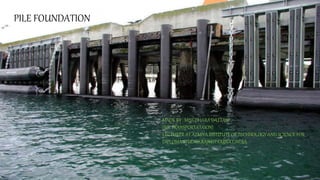
- 1. 1 PILE FOUNDATION MADE BY : MISS.DHARA DATTANI (ME TRANSPORTATAION) LECTURER AT ATMIYA INSTITUTE OF TECHNOLOGY AND SCIENCE FOR DIPLOMA STUDIES,RAJKOT.GUJRAT,INDIA.
- 2. introduction The pile foundation is used to describe a construction for the foundation of a wall or a pier, which is supported on the pile. WHERE IT IS PLACED …? The piles may be placed separately or they may be placed in the form of cluster throughout the length of the wall. Where it is adopted …? Piles are adopted when the loose soil extended to a great depth. The load of the structure is transmitted by the piles to hard stratum below or it is resisted by the friction developed on the sided of the piles. 2
- 3. Necessity of pile foundation Where the load coming from the structure is very high & the distribution of the load on soil is uneven. The subsoil water level is likely to rise or fall appreciably. The pumping of subsoil water is too costly for keeping the foundation trench in dry condition. The construction of raft foundation is likely to be very expensive or it is likely to practically impossible. The piles are considered to be long when their length exceeds 30 meters. The structure is situated on sea shore or river bed and the foundation is likely to adopted by the scouring action of water. The piles are also used as anchors. They may be designed to give lateral support or to resist an upward pressure of uplift pressure. 3
- 4. Classification of piles based on function End bearing pile Friction pile Compaction pile Tension / uplift pile Anchor pile Fender pile / Dolphin Sheet pile Better pile 4 Civil Engineering Dept., MEFGI
- 5. End Bearing Piles & Friction Piles END BEARING PILES These piles are used to transfer the load through water or soft soil of ground to asuitable hard bearing stratum. FRICTION PILES These piles are used to transfer loads to a depth of a friction load carrying material by mean of a skin friction along the length of piles 5
- 6. COMPACTIONPILES: Compaction piles are used to compact loose granular soil, thus increasing their bearing capacity. The compaction piles themselves don’t carry load. The pile tube, driven to compact the soil, is gradually taken out and sand is filled in its place thus forming a ‘sand pile’. 6
- 7. Tension Pile or Uplift Pile These piles anchor down the structure subjected to uplift due to hydrostatic pressure or due to over-turning moment. ANCHOR PILE : These provide anchorage against the horizontal pull from sheet pulling or any other pulling. 7
- 8. Fender Pile These are used to protect water from structure against impact from ships or other floating objects. 8
- 9. Sheet Piles These pile are used as a impervious cut off sheet to reduce seepage and uplift under hydraulic structure 9
- 10. Batter Piles These piles are used to resist large horizontal or inclined forces 10
- 11. BASED ON THE MATERIAL & COMPOSITION 1. Concrete Pile 2. Timber Pile 3. Steel Pile 4. Composite Pile: Concrete & Timber, Concrete & Steel BASED ON THE METHOD OF INSTALLATION 1. Driven Pile 2. Cast-in-situ Pile 3.Driven and cast- in- situ Pile 11 CLASSIFICATION of piles
- 12. CONT… BASED ON THE LOAD CARRYING CHARECTERISTICS 1. End Bearing Piles. 2. Friction Piles. 3. Combined End Bearing and Friction Piles. 12
- 13. DIFFERENT TYPES OF PILES BASED ON MATERIAL13
- 14. BASED ON THE MATERIAL & COMPOSITION CONCRETE PILE 1. precast piles 2. cast in situ piles and 3. prestressed concrete piles Advantages: High capacity, relatively inexpensive, usually durable and corrosion resistant in many environments (not marine). Disadvantages: Handling, splicing, and transportation difficulties (for precast piles). Soil caving in cast in situ piles. 14
- 15. STEEL PILES: Type of steel pile commonly used as: 1. H PILES 2. BOX PILES 3. TUBE PILES 15 BASED ON THE MATERIAL & COMPOSITION
- 16. CONT… H-piles BOX PILES Tube Piles Wide flange section rectangle or octagonal shape driven in normal ground Small cross section area when H piles cannot drive in hard-strata Easily driven in soil Used as long pile High bearing capacity 16
- 17. Advantages and Disadvantages of Steel Piles These piles can easily withstand the stresses due to driving. These piles can resist lateral forces in a better way These piles can be easily lengthened by welding and can also be cut off easily The bearing capacity of these piles is comparatively high These piles can take up impact stresses Disadvantages: High cost, difficulty in delivery, relatively higher corrosion, noisy driving. 17
- 18. Timber Piles It is made up from trunk trees. They may be square, circular or square. Diameter of circular is 30cm to 50cm and length not exceeding 20 times of its width. At bottom cast iron shoe is provided, at top steel plate is provided. If group of piles are driven, then a concrete cap is provided to have a uniform platform. They are not permanent , because its bearing capacity is low. 18
- 19. 19
- 20. Advantages and disadvantages Easily available Length is adjusted by cutting. Can be remove easily No skilled person is required. Piles do not need heavy equipment for driving Deteoriate due to soil, salty water or insects. It cannot take heavy loads. It cannot drive into the hard ground. 20
- 21. Composite piles Combination of two different materials of piles are driven together. This piles are driven one over another. Advantage is taken of durability of concrete and the timber pile. Timber pile just at the lowest level. Advantages They are economical Easy to construct This are suitable in ground conditions where other piles are unsuitable 21
- 22. 22
- 23. SAND PILE For this piles they are driven by making holes in to ground and then filling with sand It is placed up to 2 m to 3m. It is easy to construct and can be used for any position of water table. Not suitable for loose or wet soil or where there is danger of scour. Not suitable in the regions of earthquake. 23
- 24. BASED ON METHOD OF INSTALATION 1. DRIVEN PILES : Applying load by applying blows with a heavy hammer on their tops. Timber, steel, concrete piles installed by driving. Position : inclined or vertical. 2. DRIVEN AND CAST IN SITU PILES : It is driven with a closed end in bottom. Casing is filled later with concrete. If casing is withdrawn called as uncased pile. If not withdrawn it is called as pile. 24
- 25. 3. BORED AND CAST IN SITU PILES : Excavating a hole into ground and then filling with concrete 4. SCREW PILES : This piles are screwed into the soil. 5. JACKED PILES : Piles are Driven with Hydraulic Jack 25
- 26. BASED ON LOAD CARRYING CAPACITY 1. End Bearing Piles. 2. Friction Piles. 3. Combined End Bearing and Friction Piles. 26
- 27. BASED ON LOAD CARRYING CAPACITY Combined End Bearing and Friction Piles. At bottom end bearing pile and friction along the surface of pile shaft It depends on bearing capacity of soil below and skin friction along surface of the pile. Total load carried by pile = load carried by pile point + load carried by skin friction (Qn= Qp+Qs) 27
- 28. Factors Affecting Selection of Piles Nature of structure Loading conditions Availability of funds Avability of material and equipment's Type of soil and its properties Ground water table Self weight of pile Durability of pile Cost of pile Maintenance of pile 28
- 29. Factors Affecting Selection of Piles Length of pile required Number of piles required Facilities available of driving the piles Erosion of soil near the structure Difficulties in pile driving 29
- 30. PILE ACCESSORIES For wooden ,steel, timber, pre cast concrete piles to protect the top and bottom of the pile while driving into ground and to facilitate easy pile driving certain accessories required as under: PILE CAP PILE SHOE 30
- 31. 31
- 32. FUNCTIONS OF PILE CAP 32
- 33. PILE SHOE There for pile shoe is fitted at bottom end of pile to protect the pile and to facilitate easy pile driving Pile shoe are made up of, cast iron, steel, wrought iron. While driving wooden or steel pile by hammer the bottom end of the pile gets damaged and causing difficulty in driving. Therefore , a pile shoe is fitted at the bottom end of the pile to protect the pile and also for ease of pile driving. 33
- 34. Pile Cap and Pile Shoe Square pile shoe Wedge-shaped pile shoe Round pile shoe Steel strap pile shoe for timber piles Closed-end shoe for pipe piles Socket type shoe for timber piles 34
- 35. PILE DRIVING OPERATION OF INSERTING PILE IS CALLED PILE DRIVING EQUIPMENT USED TO ALLOW HAMMER TO FALL ON THE HEAD OF PILE IS CALLED PILE DRIVER. VARIOUS METHODS OF PILE DRIVING: HAMMER DRIVING VIBRATORY PILE DRIVER WATER JETTING AND HAMMERING PARTIAL AUGERING METHOD 35
- 36. Points considered for selection of pile driving method Type of soil at the site Cost of pile driving equipment's Avability of fluid pressure Material of pile Length of pile Ground water level 36
- 37. Hammer driving Pile frame or pile driving rig Pile hammer Leads Winches 37
- 39. Pile Frame Or Pile Driving Rig Pile drive with crawler mounted crane rig commonly used for pile driving. The hammer is guided between two parallel steel channel known as leads. 39
- 40. PILE HAMMER Types of hammer used for driving the pile are; Drop hammer Single acting hammer Double acting hammer Diesel hammer Vibratory hammer 40
- 41. Winches Winches are used for lift hammer and pile. It should be light with single drum provision or heavy with double drums. Winches may be fitted with reverse gear system. Winches are driven with diesel or petrol engines or electrical power in case of drop 41
- 42. Drop hammer The drop hammer is the oldest type of hammer used pile driving. A drop hammer is rise by a winch and Allowed to drop the top of the pile under gravity from a certain height. During the driving operation a cap is fixed to the pile and cushion is generally provided between the pile and the cap. Another cushion known as hammer cushion is placed on the pile cap on which the hammer causes the impact. 42
- 43. DROP HAMMER 43
- 44. LOAD CARRYING CAPACITY OF PILES HOW CAN WE FIND LOAD CARRYING CAPACITY OF PILES? The ultimate load carrying capacity or ultimate bearing capacity or ultimate bearing resistance of pile (Qu) is the maximum load which it can carry without failure or excessive settlements of the ground. Allowable load (Qa) on a pile is the safe load which the pile can carry safely and I is determined as, Allowable load = 𝒖𝒍𝒕𝒊𝒎𝒂𝒕𝒆 𝒍𝒐𝒂𝒅 𝑭𝑶𝑺 44
- 45. METHODS TO DETERMINE LOAD CARRYING CAPACITY Methods to determine load carrying capacity: STATIC FORMULAE DYNAMIC FORMULAE PILE LOAD TESTS PENETRATION TESTS 45
- 46. STATIC FORMULAE In static formula ultimate bearing capacity of pile is considered to the sum of end bearing pile and resistance of skin friction. Qu=Qp +Qs =qp*Ap +fs.As Where, Qp=end bearing resistance Qp= unit end bearing resistance Ap =area at the base OR tip of the pile Qs= skin friction resistance fs= unit skin friction As= surface area 46
- 47. ENGINEERING NEWS RECORD(ENR) FORMULA Qa= 𝐖𝐇 F(S+C) Where, Qa= allowable load (kN) W= wt. of the hammer(kN) H= height of the fall in mm F= F.O.S, taken as “6” S= final set (penetration) C= empirical constant 25mm for drop hammer, 2.5mm for single and double acting 47
- 48. DROP HAMMER: Qa= WH 6(S+25) SINGLE ACTING STEM HAMMER: Qa= WH 6(S+2.5) DOUBLE ACTING HAMMER: Qa= 𝑊+𝑎𝑝 ℎ 6(S+2.5) Where, a = effective area of piston(mm2) p = mean effective steam pressure ( N/mm2) 48
- 49. HILEY’S FORMULA : Qu= 𝑊ℎࣁ 𝑏 𝑆+ 𝑐 2 Where, Qu= ultimate load on pile W= weight of hammer H= height of fall of Hammer C= total elastic compression = C1+C2+C3 = temporary elastic compression of dolly and packing, pile and soil 49
- 50. 50
- 51. GROUP ACTION OF PILE Pile cannot act as a column It is difficult to drive pile absolute vertical and to place in foundation If eccentric loading occurs , pile may fail structurally due to bending stress What can we do to over come this problem? In actual structural loads are supported by several piles acting as a group,there must be minimum three piles used under a column in a triangular pattern. If we required more than three pile , it should be arrange symmetrically. It shall be arranged in symmetrically or staggered position We can also provide pile cap, which must be clealy above GL or beneath of soil 51
- 52. Pile spacing The center to center distance of successive piles is known as pile spacing. It has to be carefully designed by considering the following factors, 1) Types of piles 2) Material of piles 3) Length of piles 4) Grouping of piles 5) Load coming on piles 6) Obstruction during pile driving 7) Nature of soil through which piles are passing. 52
- 53. PILE SPACING The spacing between piles in a group can be assumed based on the following: 1-Friction piles need higher spacing than bearing piles. 2- Minimum spacing (S) between piles is 2.5. 3- Maximum spacing (S) between piles is 8.0. 53
- 54. S 2 Piles 3 Piles S 4 Piles 5 Piles S S 6 Piles 7 Piles 54
- 55. S S 8 Piles SS S S 9 Piles 12/22/2017 55
- 56. Efficiency of group of pile It is the average load per pile, when the failure of the group occurs to the load at the failure of a comparable single pile. It depends on pile(length, diameter, material etc.), spacing of pile, total number of piles in a row and number of rows,etc. 12/22/2017 56 Efficiency =
- 57. FED’S RULE According to this rule, the value of each pile is reduced by one-sixteenth on account of the effect of nearest pile in each diagonal or straight row of which the particular pile is a member 57
- 58. FED’S RULE 12/22/2017Civil Department, Mr.Mayank Parekh 58
- 59. Negative skin friction 59 What is negative skin friction? Negative skin friction is a downward shear drag acting on the pile surface due to relative downward movement of soil strata surrounding the pile. The following are some of the causes of negative skin friction: Compressible layer Recently filled soil Effective stresses increases because water table goes down
- 61. Negative skin friction Lowering of ground water table causing the shrinkage of expansive soils. Under consolidated natural or compacted soils. If the pile tip is on a stiff or hard stratum, there will be a relative downward movement of upper compressible layer of soil w.r.t. pile , due to above causes, causing a downward drag force. 61
- 62. Negative skin friction Vesic stated that downward movement as little as 0.6 inch may be sufficient to mobilize full negative skin friction. It will increase stresses on the pile and pile cap. The negative skin friction of a single pile is given by Negative skin friction load = Unit frictional resistance (downward)* Length of the pile above bottom of the compressible layer * Perimeter of the pile cross section And total downward load= negative skin friction load + live load+ dead load 62
- 63. FOR COHESIVE SOIL: Qnf= P*C*Lf Where, Qnf= negative skin friction P= perimeter of pile C=cohesion of soil Lf= length of loose fill soil 63
- 64. FOR COHESIONLESS SOIL: Qnf= 0.5P *Lf2 * γ * K * tanδ Where, P=perimeter of pile Lf= length of losse fill soil γ = unit weight of soil K= co-efficient of earth pressure δ = angle of wall friction 64
- 65. UNDER-REAMED PILES Ideal solution to foundations in black cotton soil Diameter of an under-reamed piles: 20 cm. to 50 cm and diameter of the bulb 2 to 3 times the diameter of pile Under-reamed piles: reinforced with 10 to 12 mm. dia. longitudinal bars and 6 mm. dia. of rings Provide a clear cover of 4 cm. connected by a reinforced concrete beam, known as capping beam 65
- 68. BORED COMPACTION PILES Civil Engineering Dept., MEFGI 68 BORED COMPACTION PILES
- 69. BORED COMPACTION PILES (continued..) Modification of under-reamed piles One type of cast-in-situ pile which combine the advantages of both bored and driven pile Boring the piles and concreting the pile: both method same as that for under-reamed pile, except that the reinforcement cage is not placed in the bore hole before concreting Load-carrying capacity increased - 1.5 to 2 times over normal under-reamed piles Suitable in loose to medium dense sandy and silty strata 69
- 70. Procedure: Prepare the bore hole with the help of spiral auger, using guides, and then under-ream it with the help of under-reaming tool and then Concrete the pile, without placing the reinforcement cage Place of reinforcement cage, enclosing a hollow driving pipe, on the top of freshly laid concrete Drive the driving assembly through the freshly laid concrete to the full depth by means of suitable drop weight (about 5kN), operated with the help of mechanical winches After driving through the full depth of concrete, fill concrete in the hollow drive pipe also Pipe - gradually withdrawn leaving the cage 70