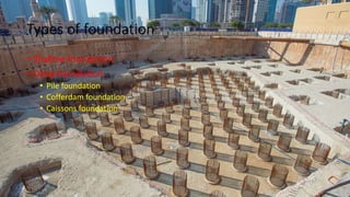
SlideShare a Scribd company logo
1 of 88
Pile foundation
Prepared by:
Thaiyam Sameer K.
Assistant Professor
Darshan Institute of Engineering & Technology
Rajkot.
Pile foundation
• Introduction
• Use of piles
• Selection of type of pile
• Types of piles
• Pile cap and pile shoes
• Pile driving equipment and method
• Micro piling
• Pulling of piles
• Causes of failure of pile
Types of foundation
• Shallow foundation
• Deep foundation
• Pile foundation
• Cofferdam foundation
• Caissons foundation
What is pile ?
• A pile is a slender structural member made of concrete, steel, wood
or composite material.
• A pile is either driven into the soil or formed in-site by excavating a
hole and filling it with concrete.
Pile foundation
• Pile foundation is that type of deep foundation in which the loads are
taken to a low level by means of vertical members which may be
 Timber
 Concrete
 steel
Uses of Piles
• The load of the super-structure is heavy and its distribution is uneven.
• The top soil has poor bearing capacity.
• The subsoil water is high so that pumping of water from the open
trenches for the shallow foundation is difficult and uneconomical.
• Large fluctuation in subsoil water level.
• The structure is situated on sea shore or river bed, where there is
danger of scouring action of water.
• Canal or deep drainage line exist near the foundation.
• For foundation of transmission towers and off-shore platforms which
are subjected to uplift forces.
Scouring
Off shore platform
Transmission Tower
Factor Affecting Selection Of Type Of Piles
• Nature and type of structure
• Location
• Material, equipment and fund availability
• Type of soil and its properties
• Ground water table
• Durability of pile
• Length and number of pile
• Case study of adjacent building
• Facility for pile driving
• Erosion of soil near structure
Classification of Piles
• Based on function
• Based on materials
• Based on method of installation
Based on function
• End bearing Pile
• Friction Pile
• Compaction Pile
• Tension Pile
• Anchor Pile
• Fender Pile
• Better Pile
• sheet Pile
End bearing Pile
• Penetrate through the soft soil
• Bottom or tips rest on hard
strata
• Work as column
• For this pile Qu=Qp
where, Qu=ultimate load
Qp= Pile load
Friction Pile
• Loose soil extend to a greater depth
• Pile are driven at depth when friction
resistance developed equal to load
• In that case Qu=Qs (Qs= skin friction)
• Total friction resistance can be increased
• Increasing length and diameter
• Making Pile surface rough
• Placing closely or grouping of pile
Compaction Pile
• Pile do not carry any load
• For increase the bearing
capacity of soil
Tension pile
• When structure subjected
to uplift due to hydrostatic
pressure or over turning
moment
• Also known as uplift pile
Anchor piles
• These provided anchorage
against the horizontal pull
from sheet pulling or any
other pulling.
Fender pile
• These are used to protect
water front structures
against impact from ships
or other floating objects.
Better Pile
• They are used for resist
large horizontal forces or
inclined forces.
Sheet Pile
• They are used as bulk
heads or as impervious
cutoff to reduce seepage
and uplift under hydraulic
structures.
• Sheet pile is classified as,
1. Concrete sheet piles
2. Steel sheet pile
3. Timber sheet pile
Classification Based on Pile Material
• Concrete pile
• Steel piles
• Timber piles
• Composite pile
• Sand pile
Concrete Piles
• Pre cast piles
• Cast-in-situ
• Pre stressed
Pre Cast Concrete Pile
• It is those which are manufactured in factory or at a place away from
the construction site and then driven into ground at the place
required.
• It requires heavy pile driving machinery.
• It may be square, octagonal or circular in cross section.
• Size of pile vary from 30 cm to 50 cm in cross section and up to 20 m
or more length.
• Grade of concrete should be M20.
Cast In Situ
• A bore is dug into the ground by inserting a casing.
• Bore is filled with cement concrete after placing
reinforcement
• The casing be kept in position or it may be withdraw.
• The piles with casing are known as cased cast in situ
concrete pile.
• The piles without casing are known as uncased cast in situ
concrete pile.
Cased
• Raymond piles
• Mac Arthur piles
• BSP base driven piles
• Swage piles
• Button bottom piles
Raymond Pile
• It used primarily as a friction pile.
• It is provided with uniform taper of 1 in 30
shorter pile.
• The length of piles vary from 6 to 12 m.
• Top diameter= 40 to 60 cm.
• Bottom diameter = 20 to 30 cm
• Collapsible mandrel is driven into ground.
• When the pile is driven to the desired
depth mandrel is collapsed and withdraw.
• The shell is gradually filled with concrete
up to the top.
Mac Arthur pile
• Mac Arthur is pile of uniform diameter
using the corrugated steel shell which
remain in place as in Raymond piles.
• A heavy steel casing with a core is
driven into the ground.
• When the desired depth is reached,
the core is withdrawn and a
corrugated steel shell is placed in the
casing.
• Concrete is placed in the shell by
gradually compacting and withdrawing
the steel casing.
BSP base driven piles
• This pile consist of a helically welded
shell of steel plate.
• A concrete plug is provided at the
bottom of the shell.
• Driving is done by allowing hammer to
fall on the concrete plug.
• The casing is driven to the desired depth
and then it is filled with concrete.
Swage piles
• It is used with advantage of driving in very
hard or it is designed to leave water tight
shell for some time filling of the concrete.
• steel shell is placed on a precast concrete
plug
• Pipe is driven over plug until the core
reached the plug, then pipe is swage out by
tapper of plug which form water tight joint.
• Pipe is driven up to specified depth by help
of driven force of core.
• Core is removed and pipe is filled with
concrete.
Button Bottom piles
• It is used where increase of end bearing
area is required.
• Pile use concrete plug shape of button
which enlarge hole in soil during driving.
• It used for length up to 23 m and load up
to 50 tones.
• 12 mm thick steel pipe set on concrete
button which have diameter of 25 mm.
• Pipe and button driven to specified depth.
• The casing is removed and concrete is
placed with reinforcement.
Uncased
• Simplex
• Franki
• Vibro
• Pedestal
• Pressure
Simplex Piles
• Simplex piles can be driven through
soft or hard soil.
• Steel tube fitted with a cast iron
shoe is driven into ground up to
desired depth.
• If Reinforcement is necessary it put
in tube then concrete is poured in
pile.
• Tube is withdrawn slowly without
concrete being tamped.
Franki Piles
• It is used at placed where high load is
transfer.(ex .marine structure)
• Plug of dry concrete is formed on
ground by heavy removable pipe shell.
• By help of Diesel operated hammer of
20 to 30 KN weight plug is driven at
desired depth.
• Diameter of pile is 50 to 60 cm ,while
at enlargement is about 90 cm.
• Capacity of pile is 60 tones to 90 tones.
Vibro Piles
• This type of pile is best suited for places where
the ground is soft and offers little frictional
resistance to the flow of concrete.
• Pile are formed by driving a steel tube and shoe,
filling with concrete and withdraw steel tube.
• Diameter of pile 35 to 50 cm for load of 60 to 70
tones. Length of pile is 25 m and above.
• Steel tube fitted with cast iron shoe by 2-2.5
tone hammer by 40 blow per minute, with stroke
about 1.4 m
• When shoe and tube reached the desired level
tube is filled with concrete and tube is
withdrawn at 80 blow per minute by hammer.
• Steel tube is withdrawn leaving the shoe in place
and pile is formed with corrugation along its
height.
Pedestal Pile
• It is used where thin bearing stratum is
reached with reasonable depth.
• Pedestal pile gives the effect of spread
footing on thin bearing stratum.
• Core and casing are driven together
into the ground till reached the desired
level.
• Core is taken out and a charge of
concrete is placed in the tube.
• The core is again placed in the casing
to rest on the top of poured concrete.
• Pressure is applied on the concrete
though the core, and as the same time
the casing is withdrawn.
Pressure Pile
• These piles are especially suitable for
congested site where heavy vibration and
noise are not permissible.
• Boring is done up to required depth to tube.
• After withdrawn boring tool reinforcement is
placed if required.
• A layer of concrete is laid and pressure cap is
provided at the top of tube.
• Compressed air is admitted through pipe
which cause rise the tube.
• Tube is lifted same time of concreting is doing
by means of compressed air.
• Care should be taken that some portion of
concrete remain at bottom when tube is
lifting for receiving new layer.
Steel Piles
• Commonly used steel piles are;
 H-piles
 Box piles
 Tube piles
H-piles
• These pile are usually of wide
flange section.
• They are suitable for trestle type
structure in which pile extend
above ground level and act as
column.
• They have small cross section
area, there for they can be easily
driven In soil.
• It used as long pile with high
bearing capacity.
Box Piles
• They are rectangular or
octagonal in form filled with
concrete.
• These pile are used when not
possible to drive H-piles into
hard strata.
Tube Piles
• Tubes or piles of steel are driven
into the ground.
• Concrete is filled inside the tube
piles.
• Because of circular cross section
tube piles are easy to handle
and easy to drive in.
Timber Piles
• These pile are prepared from trunks
of trees.
• They may be circular or square .
• Diameter of pile are 30 to 50 cm and
length not exceeding 20 times its top
width.
• At bottom, a cast-iron shoe is
provided and at the top a steel plate
is fixed.
• For group pile each pile is brought at
same level and concrete plate is
provided to have common platform.
Composite Piles
• This is a type of construction in
which piles of two different
material are driven one over the
other.
• They act together to perform the
function of a single pile.
• In this pile advantage is taken of
durability of concrete piles and the
cheapest of timber pile.
• Timber pile is terminated just at
the level of ground water table.
Sand Piles
• These pile are formed by making hole in
ground and fill with the sand and well
rammed.
• The sand to be used should be moist at
time of placing.
• Bore hole diameter usually 30 cm. length
of sand pile is kept about 12 times its
diameter.
• The top of sand pile is filled with
concrete.
• Sand pile are placed at 2 to 3 m spacing.
• Load test should be carried out
determining the bearing capacity of sand
pile.
• Properly compacted sand pile can carry
load up to 100 tone/m2 or more.
Classification Based on Method of Installation
• Driven pile
• Driven and cast-in-situ pile
• Bore and cast-in-situ piles
• Screw piles
• Jacked pile
Driven pile
• These pile are driven into
ground by applying blow with a
heavy hammer.
• Timber, steel and precast
concrete pile are installed by
driving.
Driven and cast-in-situ
pile
• These pile are formed by driving
a casing with a closed bottom
end into the soil .
• The casing is later filled with
concrete.
• The casing may or may not be
withdrawn.
Bore And Cast-in-Situ
Piles
• These pile are formed by
excavating a hole into the
ground and then filling it with
concrete.
Screw Piles
Jacked pile
• These piles are jacked into the
ground by applying a downward
force by a hydraulic jack.
Under Reamed Piles
• These piles are developed by
C.B.R.I for serving foundation for
black cotton soils, filled up ground
and other type of soil having poor
bearing capacity.
Under reamed piles
• An under reamed pile is bored cast-in-situ
concrete pile having one or more bulbs or under
reamed in its lower level.
• The bulb or under reamed are formed by under
reaming tool.
• Diameter of pile is 20 to 50 cm and bulb diameter
is 2-3 times of diameter of pile.
• Length of pile is 3 to 8 m and spacing between
piles are 2 to 4 m.
• Load carrying capacity can increase by making
more bulb at the base.
• The vertical spacing between two bulb is varies
from 1.25 to 1.5 times diameter of bulb.
• For black cotton soil the bulb is increase bearing
capacity and also provide anchorage against
uplift.
Construction of Under Reamed Piles
• The equipment required for the construction of pile are,
1. Spiral auger - for boring
2. Under reamer - for making bulb
3. Boring guide -to keep the hole vertical
Boring Using
Spiral Auger
Making Bulb Using
Under Reamer
Placing of Concrete
Placing of
Reinforcement
Pile Accessories
• Pile cap
• Pile shoe
Pile Cap
• To protect the top of pile from blow
of hammer on top, pile cap is
provided.
• Pile carry load from structure and
distribute it to various pile.
• Generally, Pile cap is made of steel.
Thickness and size of cap is depend
on shape and size of pile hammer.
• Pile should penetrate into the cap
at least 10 cm length.
• For group pile a common R.C.C. is
provided for all the pile.
Pile shoe
• There for pile shoe is fitted at
bottom end of pile to protect the
pile and to facilitate easy pile
driving.
• Pile shoe are made of cast iron,
steel or wrought iron.
• Various types of shoe are;
Square pile shoe
Wedged shaped pile shoe
Round pile shoe
Steel trap pile shoe for timber pile
Socket type pile shoe for timber pile
 closed end shoe for pipe piles
Pile driving Equipment
• The operation of inserting pile into ground is known as pile driving.
• Pile are driven into the ground by means of hammer.
• The equipment used for lifting hammer and allow to fall on head of
pile is known as Pile driver.
• Various method for pile driving are;
• Hammer driving
• Vibratory pile driver
• Watter jetting and hammering
• Partial angering method
Factor for selection of pile driving method
• Type of soil at site
• Costs of pile driving equipment
• Availability of fluid pressure
• Material of pile
• Length of pile
• Ground water level
• etc……
Hammer driving
• Equipment required for hammer driving
 Pile frame or pile driving rig
 Pile hammer
 Leads
 Winches
 Miscellaneous equipment
Pile Frame Or Pile Driving Rig
• Pile drive with crawler mounted
crane rig commonly used for pile
driving.
• The hammer is guided between
two parallel steel channel known
as leads.
Leads
• Leads are also called leaders.
• It is used to guide hammer and
pile for alignment.
• In case of drop hammer fixed
lead are used.
• Lead can be movable and can be
adjusted as per the requirement.
• Movable leads are more
convenient as they can adjusted
as required.
Winches
• Winches are used for lift hammer and
pile.
• It should be light with single drum
provision or heavy with double drums.
• Winches may be fitted with reverse
gear system.
• Winches are driven with diesel or
petrol engines or electrical power in
case of drop hammer and pneumatic
hammers.
Pile hammer
• Types of hammer used for driving
the pile are;
• Drop hammer
• Single acting hammer
• Double acting hammer
• Diesel hammer
• Vibratory hammer
1. Drop hammer
• The drop hammer is the oldest type of
hammer used pile driving.
• A drop hammer is rise by a winch and
allowed to drop the top of the pile
under gravity from a certain height.
• During the driving operation a cap is
fixed to the pile and cushion is
generally provided between the pile
and the cap.
• Another cushion known as hammer
cushion is placed on the pile cap on
which the hammer causes the impact.
2.Single acting hammer
• In this hammer the ram is raised
by air or steam under pressure to
the required height.
• It is then allowed to fall under
gravity on the top of the pile cap.
• The weight of hammer is about
1000 kg to 10,000 kg.
3. Double acting hammer
• In double acting hammer raise by using air or
steam pressure and drop the hammer.
• When hammer has been raised to the
required height steam or air pressure is
applied to other side of piston and the
hammer is pushed downward under pressure.
• The weight of the hammer may be about 1000
kg to 2500 kg.
• It can be apply 90 to 240 blow per minute.
• It is used for driving light to moderate weight
piles in soils of average resistance against
driving.
Vibratory hammer
Pulling Of Pile
• To replace the damaged piles during the driving operation.
• To reuse the existing piles when the structure above the pile is
demolished.
• To prepare the data of strata trough which piles are to be driven by
carrying out pulling tests.
• To remove the pile which are driven temporarily as in case of a
cofferdam.
Method For Pulling Of Pile
• The method for pulling of piles will depend on the type of pile,
equipment availability.
• Various method are;
 Use of double acting steam hammer
 Use of pile extractors
 Use of tongs
 Use of vibrator
 Use of electricity
Pile Extractor
Vibration Pulling
Failure of Pile
Causes Of Failure Of Pile
• Most common causes of failure of piles;
• Absence of statistical data of nature of soil strata
• Load coming on pile is high than design load.
• Bad workmanship
• Attack by insets on wood
• Breakage due to over driving (timber pile)
• Buckling of pile
• Damage due to absence of protective cover
• Improper type of pile, method of driving, classification of soil
• Insufficient reinforcement in case of R.C.C
• Misinterpretation of result from pile load test.
• Wrong formula use for determining load bearing capacity.
Causes of Failure of R.C.C. piles
• Improperly designed concrete mix.
• Use of wrong type of cement
• Insufficient concrete cover to the reinforcement
• Early removal of concrete form.
• Use of aggregate that react with the type of cement.
Micro pilling
• A Micro pile is a small
diameter, typically less than
300mm.
• A drilled and grouted non-
displacement pile which is
heavily reinforced and carries
most of its loading on the high
capacity steel reinforcement.
• Reinforcement and cement
grout are the major
component of micro pile.
• It also known as mini pile.
Construction of micro pile
• Following step are carried out for construction of micro pile.
 Drilling and/or installation of temporary casing
 Remove inner drilling bit rod.
 Placing reinforcement and grouting by tremie.
 Remove temporary casing, inject further grout under pressure.
 Complete pile (casing may be left in place of compressible stratum)
Application of micro pile
• For structure support
• New foundation
• Under pinning of existing
foundation
• Seismic retrofitting of existing
structure
• Scour protection
• Excavation support in confined
area
• For situ reinforcement
• Slop stabilization
• Earth retention
• Ground strengthening and
protection
• Settlement reduction
Advantages of micro pile
• It used to underpin the existing structure where need of minimum
vibration
• It can be easily laid where low head room is constraint.
• It can be installed at any angle.
• It offers practical and cost effective solution to costly alternative pile
system.
• Not require large access road or drilling platforms
Pile driving formula
• Load carrying capacity of pile can be determine following method;
1. Dynamic formula
2. Static formula
Dynamic formula
• Dynamic pile formula are useful in estimating pile capacity.
• The dynamic formula are based on assumption that the kinetic energy delivered by hammer
during driving operation is equal to the work done in penetrating the pile.
Kinematic energy delivered=work done in penetration
Whηh = R x s + energy loss
W=weight of hammer (KN)
h= height of fall of hammer
ηh = Efficiency of hammer
 R= pile resistance taken equal to Qu
S=penetration of pile per blow
Various Dynamic formula
• Engineering News Record (ENR) formula
• Hiley’s formula
• Danish formula
Engineering News Record formula
• As per the Engineering News formula the allowable load of driven pile
is given by
Qa=
Wh
F(s+c)
Qa= Allowable load in kg
W = Weight of hammer
h = Height of fall in mm
s = Final settlement per blow known as set
c = Empirical constant ( drop hammer= 25 mm, single acting hammer=2.5 mm)
F = Factor of safety (Usually taken as 6)
Hiley’s formula
• Hiley’s gave the formula which take into various energy loss.
Qu =
Whηh
(S + C/2)
Qu=ultimate load on pile
W=weight of hammer
h= Height of fall of hammer
C=elastic compression
ηh =efficiency of hammer
(drop hammer=100%,single acting hammer= 75-85 %,double acting =85%)
S= Avg. settlement per blow
Danish formula
• Qu =
Whηh
(S + S0/2)
S0=Elastic compression of pile
S0={2ηh (WhL)
(S + S0/2)
}1/2
L= Length of pile
A= Area of cross section of pile
E=Modulus of elasticity of pile material Allowable
Static Formula
• In static formula ultimate bearing capacity of pile is considered to the
sum of end bearing pile and resistance of skin friction.
Qu=Qp +Qs
=qp.Ap +fs.As
Where,
Qp=end bearing resistance
qp= unit end bearing resistance
Ap =area at the base
Qs= skin friction resistance
fs= unit skin friction
As= surface area
Pile foundations

More Related Content

What's hot (20)

Pile load test
Pile load testPile load test
Pile load test
 
Shoring and underpinning
Shoring and underpinningShoring and underpinning
Shoring and underpinning
 
Pile foundations_Advanced Construction Technology
Pile foundations_Advanced Construction TechnologyPile foundations_Advanced Construction Technology
Pile foundations_Advanced Construction Technology
 
Diaphragm wall: Construction and Design
Diaphragm wall: Construction and DesignDiaphragm wall: Construction and Design
Diaphragm wall: Construction and Design
 
Deep foundation
Deep foundationDeep foundation
Deep foundation
 
Pre-stressed Concrete
Pre-stressed ConcretePre-stressed Concrete
Pre-stressed Concrete
 
Prestressed concrete
Prestressed concretePrestressed concrete
Prestressed concrete
 
Underpinning
UnderpinningUnderpinning
Underpinning
 
Jacketing
JacketingJacketing
Jacketing
 
Design of rcc structures
Design of rcc structuresDesign of rcc structures
Design of rcc structures
 
Raft foundation ppt by kamal bhatia
Raft foundation ppt by kamal bhatiaRaft foundation ppt by kamal bhatia
Raft foundation ppt by kamal bhatia
 
Design of staircases
Design of staircasesDesign of staircases
Design of staircases
 
Cofferdams
Cofferdams Cofferdams
Cofferdams
 
Retaining walls
Retaining walls Retaining walls
Retaining walls
 
Pile foundation ppt
Pile foundation pptPile foundation ppt
Pile foundation ppt
 
Shoring
ShoringShoring
Shoring
 
1.PILE FOUNDATION (ACE) 2160601 GTU
1.PILE FOUNDATION (ACE) 2160601 GTU1.PILE FOUNDATION (ACE) 2160601 GTU
1.PILE FOUNDATION (ACE) 2160601 GTU
 
Prestressed concrete
Prestressed concretePrestressed concrete
Prestressed concrete
 
Concrete
ConcreteConcrete
Concrete
 
What is post tensioning
What is post tensioningWhat is post tensioning
What is post tensioning
 

Similar to Pile foundations (20)

Pile foundation
Pile foundationPile foundation
Pile foundation
 
Pile foundations Case Study Delhi Metro Site Visit
Pile foundations Case Study  Delhi Metro Site VisitPile foundations Case Study  Delhi Metro Site Visit
Pile foundations Case Study Delhi Metro Site Visit
 
Presentation tos
Presentation tosPresentation tos
Presentation tos
 
Chapter 1 PILE FOUNDATIONS
Chapter 1 PILE FOUNDATIONSChapter 1 PILE FOUNDATIONS
Chapter 1 PILE FOUNDATIONS
 
Pile foundation
Pile foundationPile foundation
Pile foundation
 
Foundation
FoundationFoundation
Foundation
 
BC-II lec 6 pierand deep fdn.pptx
BC-II lec 6 pierand deep fdn.pptxBC-II lec 6 pierand deep fdn.pptx
BC-II lec 6 pierand deep fdn.pptx
 
pire and well.pptx
pire and  well.pptxpire and  well.pptx
pire and well.pptx
 
Building foundation
Building foundationBuilding foundation
Building foundation
 
foundationtypes-161207082056.pdf
foundationtypes-161207082056.pdffoundationtypes-161207082056.pdf
foundationtypes-161207082056.pdf
 
TYPES OF FOUNDATION.pptx
TYPES OF FOUNDATION.pptxTYPES OF FOUNDATION.pptx
TYPES OF FOUNDATION.pptx
 
Advance Construction Technology
Advance Construction Technology Advance Construction Technology
Advance Construction Technology
 
Pile Foundations and Diaphragm Walls
Pile Foundations and Diaphragm WallsPile Foundations and Diaphragm Walls
Pile Foundations and Diaphragm Walls
 
CAISSON PPT.pptx
CAISSON PPT.pptxCAISSON PPT.pptx
CAISSON PPT.pptx
 
Slabs and types
Slabs and typesSlabs and types
Slabs and types
 
Deep Foundation (Construction Engineering)
Deep Foundation (Construction Engineering)Deep Foundation (Construction Engineering)
Deep Foundation (Construction Engineering)
 
Pile Foundation - Rohan Dasgupta.pdf
Pile Foundation - Rohan Dasgupta.pdfPile Foundation - Rohan Dasgupta.pdf
Pile Foundation - Rohan Dasgupta.pdf
 
Pile foundations
Pile foundationsPile foundations
Pile foundations
 
Pile
PilePile
Pile
 
DEEP FOUNDATION
DEEP FOUNDATIONDEEP FOUNDATION
DEEP FOUNDATION
 

Recently uploaded

Architect Hassan Khalil Portfolio for 2024
Architect Hassan Khalil Portfolio for 2024Architect Hassan Khalil Portfolio for 2024
Architect Hassan Khalil Portfolio for 2024hassan khalil
 
Study on Air-Water & Water-Water Heat Exchange in a Finned Tube Exchanger
Study on Air-Water & Water-Water Heat Exchange in a Finned Tube ExchangerStudy on Air-Water & Water-Water Heat Exchange in a Finned Tube Exchanger
Study on Air-Water & Water-Water Heat Exchange in a Finned Tube ExchangerAnamika Sarkar
 
Decoding Kotlin - Your guide to solving the mysterious in Kotlin.pptx
Decoding Kotlin - Your guide to solving the mysterious in Kotlin.pptxDecoding Kotlin - Your guide to solving the mysterious in Kotlin.pptx
Decoding Kotlin - Your guide to solving the mysterious in Kotlin.pptxJoão Esperancinha
 
CCS355 Neural Network & Deep Learning UNIT III notes and Question bank .pdf
CCS355 Neural Network & Deep Learning UNIT III notes and Question bank .pdfCCS355 Neural Network & Deep Learning UNIT III notes and Question bank .pdf
CCS355 Neural Network & Deep Learning UNIT III notes and Question bank .pdfAsst.prof M.Gokilavani
 
complete construction, environmental and economics information of biomass com...
complete construction, environmental and economics information of biomass com...complete construction, environmental and economics information of biomass com...
complete construction, environmental and economics information of biomass com...asadnawaz62
 
Introduction-To-Agricultural-Surveillance-Rover.pptx
Introduction-To-Agricultural-Surveillance-Rover.pptxIntroduction-To-Agricultural-Surveillance-Rover.pptx
Introduction-To-Agricultural-Surveillance-Rover.pptxk795866
 
main PPT.pptx of girls hostel security using rfid
main PPT.pptx of girls hostel security using rfidmain PPT.pptx of girls hostel security using rfid
main PPT.pptx of girls hostel security using rfidNikhilNagaraju
 
Internship report on mechanical engineering
Internship report on mechanical engineeringInternship report on mechanical engineering
Internship report on mechanical engineeringmalavadedarshan25
 
IVE Industry Focused Event - Defence Sector 2024
IVE Industry Focused Event - Defence Sector 2024IVE Industry Focused Event - Defence Sector 2024
IVE Industry Focused Event - Defence Sector 2024Mark Billinghurst
 
Oxy acetylene welding presentation note.
Oxy acetylene welding presentation note.Oxy acetylene welding presentation note.
Oxy acetylene welding presentation note.eptoze12
 
Software and Systems Engineering Standards: Verification and Validation of Sy...
Software and Systems Engineering Standards: Verification and Validation of Sy...Software and Systems Engineering Standards: Verification and Validation of Sy...
Software and Systems Engineering Standards: Verification and Validation of Sy...VICTOR MAESTRE RAMIREZ
 
Concrete Mix Design - IS 10262-2019 - .pptx
Concrete Mix Design - IS 10262-2019 - .pptxConcrete Mix Design - IS 10262-2019 - .pptx
Concrete Mix Design - IS 10262-2019 - .pptxKartikeyaDwivedi3
 
Arduino_CSE ece ppt for working and principal of arduino.ppt
Arduino_CSE ece ppt for working and principal of arduino.pptArduino_CSE ece ppt for working and principal of arduino.ppt
Arduino_CSE ece ppt for working and principal of arduino.pptSAURABHKUMAR892774
 
Gfe Mayur Vihar Call Girls Service WhatsApp -> 9999965857 Available 24x7 ^ De...
Gfe Mayur Vihar Call Girls Service WhatsApp -> 9999965857 Available 24x7 ^ De...Gfe Mayur Vihar Call Girls Service WhatsApp -> 9999965857 Available 24x7 ^ De...
Gfe Mayur Vihar Call Girls Service WhatsApp -> 9999965857 Available 24x7 ^ De...srsj9000
 
Application of Residue Theorem to evaluate real integrations.pptx
Application of Residue Theorem to evaluate real integrations.pptxApplication of Residue Theorem to evaluate real integrations.pptx
Application of Residue Theorem to evaluate real integrations.pptx959SahilShah
 
Call Us ≽ 8377877756 ≼ Call Girls In Shastri Nagar (Delhi)
Call Us ≽ 8377877756 ≼ Call Girls In Shastri Nagar (Delhi)Call Us ≽ 8377877756 ≼ Call Girls In Shastri Nagar (Delhi)
Call Us ≽ 8377877756 ≼ Call Girls In Shastri Nagar (Delhi)dollysharma2066
 
UNIT III ANALOG ELECTRONICS (BASIC ELECTRONICS)
UNIT III ANALOG ELECTRONICS (BASIC ELECTRONICS)UNIT III ANALOG ELECTRONICS (BASIC ELECTRONICS)
UNIT III ANALOG ELECTRONICS (BASIC ELECTRONICS)Dr SOUNDIRARAJ N
 
VICTOR MAESTRE RAMIREZ - Planetary Defender on NASA's Double Asteroid Redirec...
VICTOR MAESTRE RAMIREZ - Planetary Defender on NASA's Double Asteroid Redirec...VICTOR MAESTRE RAMIREZ - Planetary Defender on NASA's Double Asteroid Redirec...
VICTOR MAESTRE RAMIREZ - Planetary Defender on NASA's Double Asteroid Redirec...VICTOR MAESTRE RAMIREZ
 

Recently uploaded (20)

Architect Hassan Khalil Portfolio for 2024
Architect Hassan Khalil Portfolio for 2024Architect Hassan Khalil Portfolio for 2024
Architect Hassan Khalil Portfolio for 2024
 
Design and analysis of solar grass cutter.pdf
Design and analysis of solar grass cutter.pdfDesign and analysis of solar grass cutter.pdf
Design and analysis of solar grass cutter.pdf
 
Study on Air-Water & Water-Water Heat Exchange in a Finned Tube Exchanger
Study on Air-Water & Water-Water Heat Exchange in a Finned Tube ExchangerStudy on Air-Water & Water-Water Heat Exchange in a Finned Tube Exchanger
Study on Air-Water & Water-Water Heat Exchange in a Finned Tube Exchanger
 
Decoding Kotlin - Your guide to solving the mysterious in Kotlin.pptx
Decoding Kotlin - Your guide to solving the mysterious in Kotlin.pptxDecoding Kotlin - Your guide to solving the mysterious in Kotlin.pptx
Decoding Kotlin - Your guide to solving the mysterious in Kotlin.pptx
 
young call girls in Green Park🔝 9953056974 🔝 escort Service
young call girls in Green Park🔝 9953056974 🔝 escort Serviceyoung call girls in Green Park🔝 9953056974 🔝 escort Service
young call girls in Green Park🔝 9953056974 🔝 escort Service
 
CCS355 Neural Network & Deep Learning UNIT III notes and Question bank .pdf
CCS355 Neural Network & Deep Learning UNIT III notes and Question bank .pdfCCS355 Neural Network & Deep Learning UNIT III notes and Question bank .pdf
CCS355 Neural Network & Deep Learning UNIT III notes and Question bank .pdf
 
complete construction, environmental and economics information of biomass com...
complete construction, environmental and economics information of biomass com...complete construction, environmental and economics information of biomass com...
complete construction, environmental and economics information of biomass com...
 
Introduction-To-Agricultural-Surveillance-Rover.pptx
Introduction-To-Agricultural-Surveillance-Rover.pptxIntroduction-To-Agricultural-Surveillance-Rover.pptx
Introduction-To-Agricultural-Surveillance-Rover.pptx
 
main PPT.pptx of girls hostel security using rfid
main PPT.pptx of girls hostel security using rfidmain PPT.pptx of girls hostel security using rfid
main PPT.pptx of girls hostel security using rfid
 
Internship report on mechanical engineering
Internship report on mechanical engineeringInternship report on mechanical engineering
Internship report on mechanical engineering
 
IVE Industry Focused Event - Defence Sector 2024
IVE Industry Focused Event - Defence Sector 2024IVE Industry Focused Event - Defence Sector 2024
IVE Industry Focused Event - Defence Sector 2024
 
Oxy acetylene welding presentation note.
Oxy acetylene welding presentation note.Oxy acetylene welding presentation note.
Oxy acetylene welding presentation note.
 
Software and Systems Engineering Standards: Verification and Validation of Sy...
Software and Systems Engineering Standards: Verification and Validation of Sy...Software and Systems Engineering Standards: Verification and Validation of Sy...
Software and Systems Engineering Standards: Verification and Validation of Sy...
 
Concrete Mix Design - IS 10262-2019 - .pptx
Concrete Mix Design - IS 10262-2019 - .pptxConcrete Mix Design - IS 10262-2019 - .pptx
Concrete Mix Design - IS 10262-2019 - .pptx
 
Arduino_CSE ece ppt for working and principal of arduino.ppt
Arduino_CSE ece ppt for working and principal of arduino.pptArduino_CSE ece ppt for working and principal of arduino.ppt
Arduino_CSE ece ppt for working and principal of arduino.ppt
 
Gfe Mayur Vihar Call Girls Service WhatsApp -> 9999965857 Available 24x7 ^ De...
Gfe Mayur Vihar Call Girls Service WhatsApp -> 9999965857 Available 24x7 ^ De...Gfe Mayur Vihar Call Girls Service WhatsApp -> 9999965857 Available 24x7 ^ De...
Gfe Mayur Vihar Call Girls Service WhatsApp -> 9999965857 Available 24x7 ^ De...
 
Application of Residue Theorem to evaluate real integrations.pptx
Application of Residue Theorem to evaluate real integrations.pptxApplication of Residue Theorem to evaluate real integrations.pptx
Application of Residue Theorem to evaluate real integrations.pptx
 
Call Us ≽ 8377877756 ≼ Call Girls In Shastri Nagar (Delhi)
Call Us ≽ 8377877756 ≼ Call Girls In Shastri Nagar (Delhi)Call Us ≽ 8377877756 ≼ Call Girls In Shastri Nagar (Delhi)
Call Us ≽ 8377877756 ≼ Call Girls In Shastri Nagar (Delhi)
 
UNIT III ANALOG ELECTRONICS (BASIC ELECTRONICS)
UNIT III ANALOG ELECTRONICS (BASIC ELECTRONICS)UNIT III ANALOG ELECTRONICS (BASIC ELECTRONICS)
UNIT III ANALOG ELECTRONICS (BASIC ELECTRONICS)
 
VICTOR MAESTRE RAMIREZ - Planetary Defender on NASA's Double Asteroid Redirec...
VICTOR MAESTRE RAMIREZ - Planetary Defender on NASA's Double Asteroid Redirec...VICTOR MAESTRE RAMIREZ - Planetary Defender on NASA's Double Asteroid Redirec...
VICTOR MAESTRE RAMIREZ - Planetary Defender on NASA's Double Asteroid Redirec...
 

Pile foundations

  • 1. Pile foundation Prepared by: Thaiyam Sameer K. Assistant Professor Darshan Institute of Engineering & Technology Rajkot.
  • 2. Pile foundation • Introduction • Use of piles • Selection of type of pile • Types of piles • Pile cap and pile shoes • Pile driving equipment and method • Micro piling • Pulling of piles • Causes of failure of pile
  • 3.
  • 4. Types of foundation • Shallow foundation • Deep foundation • Pile foundation • Cofferdam foundation • Caissons foundation
  • 5. What is pile ? • A pile is a slender structural member made of concrete, steel, wood or composite material. • A pile is either driven into the soil or formed in-site by excavating a hole and filling it with concrete.
  • 6. Pile foundation • Pile foundation is that type of deep foundation in which the loads are taken to a low level by means of vertical members which may be  Timber  Concrete  steel
  • 7. Uses of Piles • The load of the super-structure is heavy and its distribution is uneven. • The top soil has poor bearing capacity. • The subsoil water is high so that pumping of water from the open trenches for the shallow foundation is difficult and uneconomical. • Large fluctuation in subsoil water level. • The structure is situated on sea shore or river bed, where there is danger of scouring action of water. • Canal or deep drainage line exist near the foundation. • For foundation of transmission towers and off-shore platforms which are subjected to uplift forces.
  • 9. Factor Affecting Selection Of Type Of Piles • Nature and type of structure • Location • Material, equipment and fund availability • Type of soil and its properties • Ground water table • Durability of pile • Length and number of pile • Case study of adjacent building • Facility for pile driving • Erosion of soil near structure
  • 10. Classification of Piles • Based on function • Based on materials • Based on method of installation
  • 11. Based on function • End bearing Pile • Friction Pile • Compaction Pile • Tension Pile • Anchor Pile • Fender Pile • Better Pile • sheet Pile
  • 12. End bearing Pile • Penetrate through the soft soil • Bottom or tips rest on hard strata • Work as column • For this pile Qu=Qp where, Qu=ultimate load Qp= Pile load
  • 13. Friction Pile • Loose soil extend to a greater depth • Pile are driven at depth when friction resistance developed equal to load • In that case Qu=Qs (Qs= skin friction) • Total friction resistance can be increased • Increasing length and diameter • Making Pile surface rough • Placing closely or grouping of pile
  • 14. Compaction Pile • Pile do not carry any load • For increase the bearing capacity of soil
  • 15. Tension pile • When structure subjected to uplift due to hydrostatic pressure or over turning moment • Also known as uplift pile
  • 16. Anchor piles • These provided anchorage against the horizontal pull from sheet pulling or any other pulling.
  • 17. Fender pile • These are used to protect water front structures against impact from ships or other floating objects.
  • 18. Better Pile • They are used for resist large horizontal forces or inclined forces.
  • 19. Sheet Pile • They are used as bulk heads or as impervious cutoff to reduce seepage and uplift under hydraulic structures. • Sheet pile is classified as, 1. Concrete sheet piles 2. Steel sheet pile 3. Timber sheet pile
  • 20. Classification Based on Pile Material • Concrete pile • Steel piles • Timber piles • Composite pile • Sand pile
  • 21. Concrete Piles • Pre cast piles • Cast-in-situ • Pre stressed
  • 22. Pre Cast Concrete Pile • It is those which are manufactured in factory or at a place away from the construction site and then driven into ground at the place required. • It requires heavy pile driving machinery. • It may be square, octagonal or circular in cross section. • Size of pile vary from 30 cm to 50 cm in cross section and up to 20 m or more length. • Grade of concrete should be M20.
  • 23. Cast In Situ • A bore is dug into the ground by inserting a casing. • Bore is filled with cement concrete after placing reinforcement • The casing be kept in position or it may be withdraw. • The piles with casing are known as cased cast in situ concrete pile. • The piles without casing are known as uncased cast in situ concrete pile.
  • 24. Cased • Raymond piles • Mac Arthur piles • BSP base driven piles • Swage piles • Button bottom piles
  • 25. Raymond Pile • It used primarily as a friction pile. • It is provided with uniform taper of 1 in 30 shorter pile. • The length of piles vary from 6 to 12 m. • Top diameter= 40 to 60 cm. • Bottom diameter = 20 to 30 cm • Collapsible mandrel is driven into ground. • When the pile is driven to the desired depth mandrel is collapsed and withdraw. • The shell is gradually filled with concrete up to the top.
  • 26. Mac Arthur pile • Mac Arthur is pile of uniform diameter using the corrugated steel shell which remain in place as in Raymond piles. • A heavy steel casing with a core is driven into the ground. • When the desired depth is reached, the core is withdrawn and a corrugated steel shell is placed in the casing. • Concrete is placed in the shell by gradually compacting and withdrawing the steel casing.
  • 27. BSP base driven piles • This pile consist of a helically welded shell of steel plate. • A concrete plug is provided at the bottom of the shell. • Driving is done by allowing hammer to fall on the concrete plug. • The casing is driven to the desired depth and then it is filled with concrete.
  • 28. Swage piles • It is used with advantage of driving in very hard or it is designed to leave water tight shell for some time filling of the concrete. • steel shell is placed on a precast concrete plug • Pipe is driven over plug until the core reached the plug, then pipe is swage out by tapper of plug which form water tight joint. • Pipe is driven up to specified depth by help of driven force of core. • Core is removed and pipe is filled with concrete.
  • 29. Button Bottom piles • It is used where increase of end bearing area is required. • Pile use concrete plug shape of button which enlarge hole in soil during driving. • It used for length up to 23 m and load up to 50 tones. • 12 mm thick steel pipe set on concrete button which have diameter of 25 mm. • Pipe and button driven to specified depth. • The casing is removed and concrete is placed with reinforcement.
  • 30. Uncased • Simplex • Franki • Vibro • Pedestal • Pressure
  • 31. Simplex Piles • Simplex piles can be driven through soft or hard soil. • Steel tube fitted with a cast iron shoe is driven into ground up to desired depth. • If Reinforcement is necessary it put in tube then concrete is poured in pile. • Tube is withdrawn slowly without concrete being tamped.
  • 32. Franki Piles • It is used at placed where high load is transfer.(ex .marine structure) • Plug of dry concrete is formed on ground by heavy removable pipe shell. • By help of Diesel operated hammer of 20 to 30 KN weight plug is driven at desired depth. • Diameter of pile is 50 to 60 cm ,while at enlargement is about 90 cm. • Capacity of pile is 60 tones to 90 tones.
  • 33. Vibro Piles • This type of pile is best suited for places where the ground is soft and offers little frictional resistance to the flow of concrete. • Pile are formed by driving a steel tube and shoe, filling with concrete and withdraw steel tube. • Diameter of pile 35 to 50 cm for load of 60 to 70 tones. Length of pile is 25 m and above. • Steel tube fitted with cast iron shoe by 2-2.5 tone hammer by 40 blow per minute, with stroke about 1.4 m • When shoe and tube reached the desired level tube is filled with concrete and tube is withdrawn at 80 blow per minute by hammer. • Steel tube is withdrawn leaving the shoe in place and pile is formed with corrugation along its height.
  • 34. Pedestal Pile • It is used where thin bearing stratum is reached with reasonable depth. • Pedestal pile gives the effect of spread footing on thin bearing stratum. • Core and casing are driven together into the ground till reached the desired level. • Core is taken out and a charge of concrete is placed in the tube. • The core is again placed in the casing to rest on the top of poured concrete. • Pressure is applied on the concrete though the core, and as the same time the casing is withdrawn.
  • 35. Pressure Pile • These piles are especially suitable for congested site where heavy vibration and noise are not permissible. • Boring is done up to required depth to tube. • After withdrawn boring tool reinforcement is placed if required. • A layer of concrete is laid and pressure cap is provided at the top of tube. • Compressed air is admitted through pipe which cause rise the tube. • Tube is lifted same time of concreting is doing by means of compressed air. • Care should be taken that some portion of concrete remain at bottom when tube is lifting for receiving new layer.
  • 36. Steel Piles • Commonly used steel piles are;  H-piles  Box piles  Tube piles
  • 37. H-piles • These pile are usually of wide flange section. • They are suitable for trestle type structure in which pile extend above ground level and act as column. • They have small cross section area, there for they can be easily driven In soil. • It used as long pile with high bearing capacity.
  • 38. Box Piles • They are rectangular or octagonal in form filled with concrete. • These pile are used when not possible to drive H-piles into hard strata.
  • 39. Tube Piles • Tubes or piles of steel are driven into the ground. • Concrete is filled inside the tube piles. • Because of circular cross section tube piles are easy to handle and easy to drive in.
  • 40. Timber Piles • These pile are prepared from trunks of trees. • They may be circular or square . • Diameter of pile are 30 to 50 cm and length not exceeding 20 times its top width. • At bottom, a cast-iron shoe is provided and at the top a steel plate is fixed. • For group pile each pile is brought at same level and concrete plate is provided to have common platform.
  • 41. Composite Piles • This is a type of construction in which piles of two different material are driven one over the other. • They act together to perform the function of a single pile. • In this pile advantage is taken of durability of concrete piles and the cheapest of timber pile. • Timber pile is terminated just at the level of ground water table.
  • 42. Sand Piles • These pile are formed by making hole in ground and fill with the sand and well rammed. • The sand to be used should be moist at time of placing. • Bore hole diameter usually 30 cm. length of sand pile is kept about 12 times its diameter. • The top of sand pile is filled with concrete. • Sand pile are placed at 2 to 3 m spacing. • Load test should be carried out determining the bearing capacity of sand pile. • Properly compacted sand pile can carry load up to 100 tone/m2 or more.
  • 43. Classification Based on Method of Installation • Driven pile • Driven and cast-in-situ pile • Bore and cast-in-situ piles • Screw piles • Jacked pile
  • 44. Driven pile • These pile are driven into ground by applying blow with a heavy hammer. • Timber, steel and precast concrete pile are installed by driving.
  • 45. Driven and cast-in-situ pile • These pile are formed by driving a casing with a closed bottom end into the soil . • The casing is later filled with concrete. • The casing may or may not be withdrawn.
  • 46. Bore And Cast-in-Situ Piles • These pile are formed by excavating a hole into the ground and then filling it with concrete.
  • 48. Jacked pile • These piles are jacked into the ground by applying a downward force by a hydraulic jack.
  • 49. Under Reamed Piles • These piles are developed by C.B.R.I for serving foundation for black cotton soils, filled up ground and other type of soil having poor bearing capacity.
  • 50. Under reamed piles • An under reamed pile is bored cast-in-situ concrete pile having one or more bulbs or under reamed in its lower level. • The bulb or under reamed are formed by under reaming tool. • Diameter of pile is 20 to 50 cm and bulb diameter is 2-3 times of diameter of pile. • Length of pile is 3 to 8 m and spacing between piles are 2 to 4 m. • Load carrying capacity can increase by making more bulb at the base. • The vertical spacing between two bulb is varies from 1.25 to 1.5 times diameter of bulb. • For black cotton soil the bulb is increase bearing capacity and also provide anchorage against uplift.
  • 51. Construction of Under Reamed Piles • The equipment required for the construction of pile are, 1. Spiral auger - for boring 2. Under reamer - for making bulb 3. Boring guide -to keep the hole vertical
  • 52. Boring Using Spiral Auger Making Bulb Using Under Reamer
  • 53. Placing of Concrete Placing of Reinforcement
  • 54. Pile Accessories • Pile cap • Pile shoe
  • 55. Pile Cap • To protect the top of pile from blow of hammer on top, pile cap is provided. • Pile carry load from structure and distribute it to various pile. • Generally, Pile cap is made of steel. Thickness and size of cap is depend on shape and size of pile hammer. • Pile should penetrate into the cap at least 10 cm length. • For group pile a common R.C.C. is provided for all the pile.
  • 56. Pile shoe • There for pile shoe is fitted at bottom end of pile to protect the pile and to facilitate easy pile driving. • Pile shoe are made of cast iron, steel or wrought iron. • Various types of shoe are; Square pile shoe Wedged shaped pile shoe Round pile shoe Steel trap pile shoe for timber pile Socket type pile shoe for timber pile  closed end shoe for pipe piles
  • 57. Pile driving Equipment • The operation of inserting pile into ground is known as pile driving. • Pile are driven into the ground by means of hammer. • The equipment used for lifting hammer and allow to fall on head of pile is known as Pile driver. • Various method for pile driving are; • Hammer driving • Vibratory pile driver • Watter jetting and hammering • Partial angering method
  • 58. Factor for selection of pile driving method • Type of soil at site • Costs of pile driving equipment • Availability of fluid pressure • Material of pile • Length of pile • Ground water level • etc……
  • 59. Hammer driving • Equipment required for hammer driving  Pile frame or pile driving rig  Pile hammer  Leads  Winches  Miscellaneous equipment
  • 60. Pile Frame Or Pile Driving Rig • Pile drive with crawler mounted crane rig commonly used for pile driving. • The hammer is guided between two parallel steel channel known as leads.
  • 61. Leads • Leads are also called leaders. • It is used to guide hammer and pile for alignment. • In case of drop hammer fixed lead are used. • Lead can be movable and can be adjusted as per the requirement. • Movable leads are more convenient as they can adjusted as required.
  • 62. Winches • Winches are used for lift hammer and pile. • It should be light with single drum provision or heavy with double drums. • Winches may be fitted with reverse gear system. • Winches are driven with diesel or petrol engines or electrical power in case of drop hammer and pneumatic hammers.
  • 63. Pile hammer • Types of hammer used for driving the pile are; • Drop hammer • Single acting hammer • Double acting hammer • Diesel hammer • Vibratory hammer
  • 64. 1. Drop hammer • The drop hammer is the oldest type of hammer used pile driving. • A drop hammer is rise by a winch and allowed to drop the top of the pile under gravity from a certain height. • During the driving operation a cap is fixed to the pile and cushion is generally provided between the pile and the cap. • Another cushion known as hammer cushion is placed on the pile cap on which the hammer causes the impact.
  • 65. 2.Single acting hammer • In this hammer the ram is raised by air or steam under pressure to the required height. • It is then allowed to fall under gravity on the top of the pile cap. • The weight of hammer is about 1000 kg to 10,000 kg.
  • 66. 3. Double acting hammer • In double acting hammer raise by using air or steam pressure and drop the hammer. • When hammer has been raised to the required height steam or air pressure is applied to other side of piston and the hammer is pushed downward under pressure. • The weight of the hammer may be about 1000 kg to 2500 kg. • It can be apply 90 to 240 blow per minute. • It is used for driving light to moderate weight piles in soils of average resistance against driving.
  • 68. Pulling Of Pile • To replace the damaged piles during the driving operation. • To reuse the existing piles when the structure above the pile is demolished. • To prepare the data of strata trough which piles are to be driven by carrying out pulling tests. • To remove the pile which are driven temporarily as in case of a cofferdam.
  • 69. Method For Pulling Of Pile • The method for pulling of piles will depend on the type of pile, equipment availability. • Various method are;  Use of double acting steam hammer  Use of pile extractors  Use of tongs  Use of vibrator  Use of electricity
  • 73. Causes Of Failure Of Pile • Most common causes of failure of piles; • Absence of statistical data of nature of soil strata • Load coming on pile is high than design load. • Bad workmanship • Attack by insets on wood • Breakage due to over driving (timber pile) • Buckling of pile • Damage due to absence of protective cover • Improper type of pile, method of driving, classification of soil • Insufficient reinforcement in case of R.C.C • Misinterpretation of result from pile load test. • Wrong formula use for determining load bearing capacity.
  • 74. Causes of Failure of R.C.C. piles • Improperly designed concrete mix. • Use of wrong type of cement • Insufficient concrete cover to the reinforcement • Early removal of concrete form. • Use of aggregate that react with the type of cement.
  • 75. Micro pilling • A Micro pile is a small diameter, typically less than 300mm. • A drilled and grouted non- displacement pile which is heavily reinforced and carries most of its loading on the high capacity steel reinforcement. • Reinforcement and cement grout are the major component of micro pile. • It also known as mini pile.
  • 76. Construction of micro pile • Following step are carried out for construction of micro pile.  Drilling and/or installation of temporary casing  Remove inner drilling bit rod.  Placing reinforcement and grouting by tremie.  Remove temporary casing, inject further grout under pressure.  Complete pile (casing may be left in place of compressible stratum)
  • 77.
  • 78. Application of micro pile • For structure support • New foundation • Under pinning of existing foundation • Seismic retrofitting of existing structure • Scour protection • Excavation support in confined area • For situ reinforcement • Slop stabilization • Earth retention • Ground strengthening and protection • Settlement reduction
  • 79.
  • 80. Advantages of micro pile • It used to underpin the existing structure where need of minimum vibration • It can be easily laid where low head room is constraint. • It can be installed at any angle. • It offers practical and cost effective solution to costly alternative pile system. • Not require large access road or drilling platforms
  • 81. Pile driving formula • Load carrying capacity of pile can be determine following method; 1. Dynamic formula 2. Static formula
  • 82. Dynamic formula • Dynamic pile formula are useful in estimating pile capacity. • The dynamic formula are based on assumption that the kinetic energy delivered by hammer during driving operation is equal to the work done in penetrating the pile. Kinematic energy delivered=work done in penetration Whηh = R x s + energy loss W=weight of hammer (KN) h= height of fall of hammer ηh = Efficiency of hammer  R= pile resistance taken equal to Qu S=penetration of pile per blow
  • 83. Various Dynamic formula • Engineering News Record (ENR) formula • Hiley’s formula • Danish formula
  • 84. Engineering News Record formula • As per the Engineering News formula the allowable load of driven pile is given by Qa= Wh F(s+c) Qa= Allowable load in kg W = Weight of hammer h = Height of fall in mm s = Final settlement per blow known as set c = Empirical constant ( drop hammer= 25 mm, single acting hammer=2.5 mm) F = Factor of safety (Usually taken as 6)
  • 85. Hiley’s formula • Hiley’s gave the formula which take into various energy loss. Qu = Whηh (S + C/2) Qu=ultimate load on pile W=weight of hammer h= Height of fall of hammer C=elastic compression ηh =efficiency of hammer (drop hammer=100%,single acting hammer= 75-85 %,double acting =85%) S= Avg. settlement per blow
  • 86. Danish formula • Qu = Whηh (S + S0/2) S0=Elastic compression of pile S0={2ηh (WhL) (S + S0/2) }1/2 L= Length of pile A= Area of cross section of pile E=Modulus of elasticity of pile material Allowable
  • 87. Static Formula • In static formula ultimate bearing capacity of pile is considered to the sum of end bearing pile and resistance of skin friction. Qu=Qp +Qs =qp.Ap +fs.As Where, Qp=end bearing resistance qp= unit end bearing resistance Ap =area at the base Qs= skin friction resistance fs= unit skin friction As= surface area