Downloaded 183 times

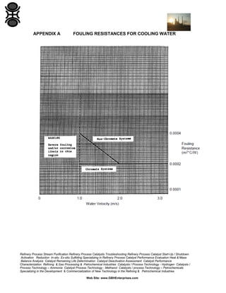
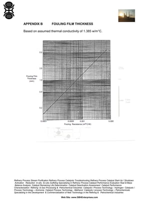

The GBH Enterprises process engineering guide provides procedures for estimating fouling resistances in cooling water systems, addressing both chromate and non-chromate designs. It emphasizes the importance of proper water treatment and adequate water velocities to minimize fouling and corrosion in heat exchangers. The guide is applicable to the process engineering community within GBH and includes detailed recommendations based on extensive operating experience and testing results.


