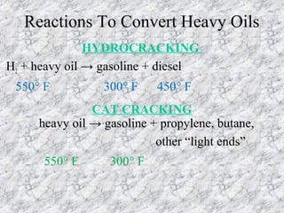
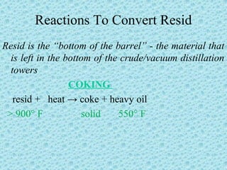
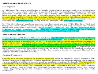
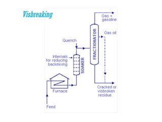
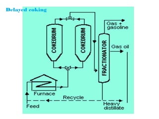
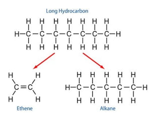
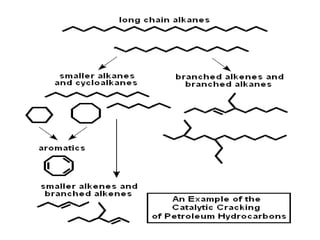
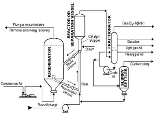
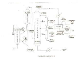
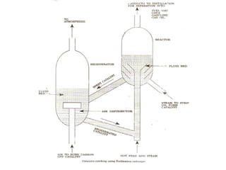
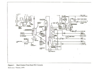
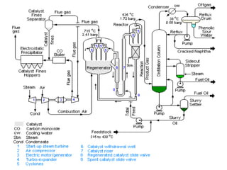
SlideShare a Scribd company logo
1 of 33
Reactions To Convert Heavy Oils
HYDROCRACKING
H2 + heavy oil → gasoline + diesel
550° F 300° F 450° F
CAT CRACKING
heavy oil → gasoline + propylene, butane,
other “light ends”
550° F 300° F
Reactions To Convert Resid
Resid is the “bottom of the barrel” - the material that
is left in the bottom of the crude/vacuum distillation
towers
COKING
resid + heat → coke + heavy oil
> 900° F solid 550° F
THERMAL CRACKING
Description
a. Because the simple distillation of crude oil produces amounts and types of products
that are not consistent with those required by the marketplace, subsequent refinery
processes change the product mix by altering the molecular structure of the
hydrocarbons. One of the ways of accomplishing this change is through "cracking," a
process that breaks or cracks the heavier, higher boiling-point petroleum fractions into
more valuable products such as gasoline, fuel oil, and gas o ils. The two basic types of
cracking are thermal cracking, using heat and pressure, and catalytic cracking.
b. The first thermal cracking process was developed around 1913. Distillate fuels and
heavy oils were heated under pressure in large drums until they cracked into smaller
molecules with better antiknock characteristics. However, this method produced large
amounts of solid, unwanted coke. This early process has evolved into the following
applications of thermal cracking: visbreaking, steam cracking, and coking.
Visbreaking Process
Visbreaking, a mild form of thermal cracking, significantly lowers the viscosity of heavy
crude-oil residue without affecting the boiling point range. Residual from the atmospheric
distillation tower is heated (800°-950° F) at atmospheric pressure and mildly cracked in a
heater. It is then quenched with cool gas oil to control overcracking, and flashed in a
distillation tower. Visbreaking is used to reduce the pour point of waxy residues and
reduce the viscosity of residues used for blending with lighter fuel oils. Middle distillates
may also be produced, depending on product demand. The thermally cracked residue tar,
which accumulates in the bottom of the fractionation tower, is vacuum flashed in a
stripper and the distillate recycled.
Coking Processes
Coking is a severe method of thermal cracking used to upgrade heavy residuals into
lighter products or distillates. Coking produces straight-run gasoline (coker naphtha) and
various middle-distillate fractions used as catalytic cracking feedstock. The process so
completely reduces hydrogen that the residue is a form of carbon called "coke." The two
most common processes are delayed coking and continuous (contact or fluid) coking.
Three typical types of coke are obtained (sponge coke, honeycomb coke, and needle
coke) depending upon the reaction mechanism, time, temperature, and the crude
feedstock.
Visbreaking
Delayed coking
CATALYTIC CRACKING
Description
a. Catalytic cracking breaks complex hydrocarbons into simpler molecules in order to
increase the quality and quantity of lighter, more desirable products and decrease the
amount of residuals. This process rearranges the molecular structure of hydrocarbon
compounds to convert heavy hydrocarbon feedstock into lighter fractions such as
kerosene, gasoline, LPG, heating oil, and petrochemical feedstock.
b. Catalytic cracking is similar to thermal cracking except that catalysts facilitate the
conversion of the heavier molecules into lighter products. Use of a catalyst in the
cracking reaction increases the yield of improved-quality products under much less
severe operating conditions than in thermal cracking. Typical temperatures are from
850°-950° F at much lower pressures of 10-20 psi. The catalysts used in refinery cracking
units are typically solid materials (zeolite, aluminum hydrosilicate, treated bentonite clay,
fuller's earth, bauxite, and silica-alumina) that come in the form of powders, beads,
pellets or shaped materials called extrudites.
c. There are three basic functions in the catalytic cracking process:
Reaction: Feedstock reacts with catalyst and cracks into different hydrocarbons;
Regeneration: Catalyst is reactivated by burning off coke; and
Fractionation: Cracked hydrocarbon stream is separated into various products.
Fluid Catalytic Cracking
FLUID CATALYTIC CRACKING
Description
a. The most common process is FCC, in which the oil is cracked in the presence of a
finely divided catalyst which is maintained in an aerated or fluidized state by the oil
vapors. The fluid cracker consists of a catalyst section and a fractionating section that
operate together as an integrated processing unit. The catalyst section contains the reactor
and regenerator, which, with the standpipe and riser, forms the catalyst circulation unit.
The fluid catalyst is continuously circulated between the reactor and the regenerator using
air, oil vapors, and steam as the conveying media.
b. A typical FCC process involves mixing a preheated hydrocarbon charge with hot,
regenerated catalyst as it enters the riser leading to the reactor. The charge is combined
with a recycle stream within the riser, vaporized, and raised to reactor temperature (900°-
1,000° F) by the hot catalyst. As the mixture travels up the riser, the charge is cracked at
10-30 psi. In the more modern FCC units, all cracking takes place in the riser. The
"reactor" no longer functions as a reactor; it merely serves as a holding vessel for the
cyclones. This cracking continues until the oil vapors are separated from the catalyst in
the reactor cyclones. The resultant product stream (cracked product) is then charged to a
fractionating column where it is separated into fractions, and some of the heavy oil is
recycled to the riser.
c. Spent catalyst is regenerated to get rid of coke that collects on the catalyst during the
process. Spent catalyst flows through the catalyst stripper to the regenerator, where most
of the coke deposits burn off at the bottom where preheated air and spent catalyst are
mixed. Fresh catalyst is added and worn-out catalyst removed to optimize the cracking
process.
In petroleum geology and chemistry, cracking is the process whereby complex organic molecules such
as kerogens or heavy hydrocarbons are broken down into simpler molecules (e.g. light hydrocarbons) by
the breaking of carbon-carbon bonds in the precursors. The rate of cracking and the end products are
strongly dependent on the temperature and presence of any catalysts. Cracking, also referred to as
pyrolysis, is the breakdown of a large alkane into smaller, more useful alkenes and an alkane. Simply
put, cracking hydrocarbons is when you separate long chain hydrocarbons into short ones.
Fluid catalytic cracking (FCC) is the most important conversion process used in petroleum refineries.
It is widely used to convert the high-boiling hydrocarbon fractions of petroleum crude oils to more
valuable gasoline, olefinic gases and other products. Cracking of petroleum hydrocarbons was originally
done by thermal cracking which has been almost completely replaced by catalytic cracking because it
produces more gasoline with a higher octane rating. It also produces byproduct gases that are more
olefinic, and hence more valuable, than those produced by thermal cracking.
The feedstock to an FCC is usually that portion of the crude oil that has an initial boiling point of 340
°C or higher at atmospheric pressure and an average molecular weight ranging from about 200 to 600 or
higher. The FCC process vaporizes and breaks the long-chain molecules of the high-boiling
hydrocarbon liquids into much shorter molecules by contacting the feedstock, at high temperature and
moderate pressure, with a fluidized powdered catalyst.
In effect, refineries use fluid catalytic cracking to correct the imbalance between the market demand for
gasoline and the excess of heavy, high boiling range products resulting from the distillation of crude oil.
Reactor and Regenerator
The preheated high-boiling petroleum feedstock (at about 315 to 430°C) consisting of long-chain
hydrocarbon molecules is combined with recycle slurry oil from the bottom of the distillation column and
injected into the catalyst riser where it is vaporized and cracked into smaller molecules of vapor by
contact and mixing with the very hot powdered catalyst from the regenerator. All of the cracking
reactions take place in the catalyst riser. The hydrocarbon vapors "fluidize" the powdered catalyst and the
mixture of hydrocarbon vapors and catalyst flows upward to enter the reactor at a temperature of about
535°C and a pressure of about 1.72 barg.
The reactor is in fact merely a vessel in which the cracked product vapors are: (a) separated from the so-
called spent catalyst by flowing through a set of two-stage cyclones within the reactor and (b) the spent
catalyst flows downward through a steam stripping section to remove any hydrocarbon vapors before the
spent catalyst returns to the catalyst regenerator. The flow of spent catalyst to the regenerator is regulated
by a slide valve in the spent catalyst line.
Since the cracking reactions produce some carbonaceous material (referred to as coke) that deposits on
the catalyst and very quickly reduces the catalyst reactivity, the catalyst is regenerated by burning off the
deposited coke with air blown into the regenerator. The regenerator operates at a temperature of about
715°C and a pressure of about 2.41 barg. The combustion of the coke is exothermic and it produces a
large amount of heat that is partially absorbed by the regenerated catalyst and provides the heat required
for the vaporization of the feedstock and the endothermic cracking reactions that take place in the catalyst
riser. For that reason, FCC units are often referred to as being heat balanced.
The hot catalyst (at about 715 °C) leaving the regenerator flows into a catalyst withdrawal well where
any entrained combustion flue gases are allowed to escape and flow back into the upper part to the
regenerator. The flow of regenerated catalyst to the feedstock injection point below the catalyst riser is
regulated by a slide valve in the regenerated catalyst line. The hot flue gas exits the regenerator after
passing through multiple sets of two-stage cylones that remove entrained catalyst from the flue gas.
The amount of catalyst circulating between the regenerator and the reactor amounts to about 5 kg per kg
of feedstock which is equivalent to about 4.66 kg per litre of feedstock. Thus, an FCC unit processing
75,000 barrels/day (12,000,000 litres/day) will circulate about 55,900 metric tons per day of catalyst.
Distillation column
The reaction product vapors (at 535 °C and a pressure of 1.72 barg) flow from the top of the reactor to
the bottom section of the distillation column (commonly referred to as the main fractionator) where they
are distilled into the FCC end products of cracked naphtha, fuel oil and off-gas. After further processing
for removal of sulfur compounds, the cracked naphtha becomes a high-octane component of the
refinery's blended gasolines.
The main fractionator off-gas is sent to what is called a gas recovery unit where it is separated into
butanes and butylenes, propane and propylene, and lower molecular weight gases (hydrogen, methane,
ethylene and ethane). Some FCC gas recovery units may also separate out some of the ethane and
ethylene.
Although the schematic flow diagram above depicts the main fractionator as having only one sidecut
stripper and one fuel oil product, many FCC main fractionators have two sidecut strippers and produce a
light fuel oil and a heavy fuel oil. Likewise, many FCC main fractionators produce a light cracked
naphtha and a heavy cracked naphtha. The terminology light and heavy in this context refers to the
product boiling ranges, with light products having a lower boiling range than heavy products.
The bottom product oil from the main fractionator contains residual catalyst particles which were not
completely removed by the cyclones in the top of the reactor. For that reason, the bottom product oil is
referred to as a slurry oil. Part of that slurry oil is recycled back into the main fractionator above the entry
point of the hot reaction product vapors so as to cool and partially condense the reaction product vapors as
they enter the main fractionator. The remainder of the slurry oil is pumped through a slurry settler. The
bottom oil from the slurry settler contains most of the slurry oil catalyst particles and is recycled back into
the catalyst riser by combining it with the FCC feedstock oil. The so-called clarified slurry oil is
withdrawn from the top of slurry settler for use elsewhere in the refinery or as a heavy fuel oil blending
component.
Regenerator flue gas
Depending on the choice of FCC design, the combustion in the regenerator of the coke on the spent
catalyst may or may not be complete combustion to carbon dioxide (CO2). The combustion air flow is
controlled so as to provide the desired ratio of carbon monoxide (CO) to carbon dioxide for each specific
FCC design.
In the design shown in Figure 1, the coke has only been partially combusted to CO2. The combustion flue
gas (containing CO and CO2) at 715 °C and at a pressure of 2.41 barg is routed through a secondary
catalyst separator containing swirl tubes designed to remove 70 to 90 percent of the particulates in the flue
gas leaving the regenerator. This is required to prevent erosion damage to the blades in the turbo-expander
that the flue gas is next routed through.
The expansion of flue gas through a turbo-expander provides sufficient power to drive the
regenerator's combustion air compressor. The electrical motor-generator can consume or
produce electrical power. If the expansion of the flue gas does not provide enough power to
drive the air compressor, the electric motor/generator provides the needed additional
power. If the flue gas expansion provides more power than needed to drive the air
compressor, than the electric motor/generator converts the excess power into electric power
and exports it to the refinery's electrical system.
The expanded flue gas is then routed through a steam-generating boiler (referred to as a CO
boiler) where the carbon monoxide in the flue gas is burned as fuel to provide steam for use
in the refinery as well as to comply with any applicable environmental regulatory limits on
carbon monoxide emissions.
The flue gas is finally processed through an electrostatic precipitator (ESP) to remove
residual particulate matter to comply with any applicable environmental regulations
regarding particulate emissions. The ESP removes particulates in the size range of 2 to 20
microns from the flue gas.
The steam turbine in the flue gas processing system is used to drive the regenerator's
combustion air compressor during start-ups of the FCC unit until there is sufficient
combustion flue gas to take over that task.
HYDROCRACKING
Description
a. Hydrocracking is a two-stage process combining catalytic cracking and
hydrogenation, wherein heavier feedstocks are cracked in the presence of hydrogen to
produce more desirable products. The process employs high pressure, high temperature, a
catalyst, and hydrogen. Hydrocracking is used for feedstocks that are difficult to process
by either catalytic cracking or reforming, since these feedstocks are characterized usually
by a high polycyclic aromatic content and/or high concentrations of the two principal
catalyst poisons, sulfur and nitrogen compounds.
b. The hydrocracking process largely depends on the nature of the feedstock and the
relative rates of the two competing reactions, hydrogenation and cracking. Heavy
aromatic feedstock is converted into lighter products under a wide range of very high
pressures (1,000-2,000 psi) and fairly high temperatures (750°-1,500° F), in the presence
of hydrogen and special catalysts. When the feedstock has a high paraffinic content, the
primary function of hydrogen is to prevent the formation of polycyclic aromatic
compounds. Another important role of hydrogen in the hydrocracking process is to
reduce tar formation and prevent buildup of coke on the catalyst. Hydrogenation also
serves to convert sulfur and nitrogen compounds present in the feedstock to hydrogen
sulfide and ammonia.
c. Hydrocracking produces relatively large amounts of isobutane for alkylation
feedstock. Hydrocracking also performs isomerization for pour-point control and smoke-
point control, both of which are important in high-quality jet fuel.
Hydrocracking Process
a. In the first stage, preheated feedstock is mixed with recycled hydrogen
and sent to the first-stage reactor, where catalysts convert sulfur and nitrogen
compounds to hydrogen sulfide and ammonia. Limited hydrocracking also
occurs.
b. After the hydrocarbon leaves the first stage, it is cooled and liquefied and
run through a hydrocarbon separator. The hydrogen is recycled to the
feedstock. The liquid is charged to a fractionator. Depending on the products
desired (gasoline components, jet fuel, and gas oil), the fractionator is run to
cut out some portion of the first stage reactor out-turn. Kerosene-range
material can be taken as a separate side-draw product or included in the
fractionator bottoms with the gas oil.
c. The fractionator bottoms are again mixed with a hydrogen stream and
charged to the second stage. Since this material has already been subjected
to some hydrogenation, cracking, and reforming in the first stage, the
operations of the second stage are more severe (higher temperatures and
pressures). Like the out-turn of the first stage, the second stage product is
separated from the hydrogen and charged to the fractionator.
HYDROGEN PRODUCTION
Description
a. High-purity hydrogen (95%-99%) is required for hydrodesulfurization, hydrogenation,
hydrocracking, and petrochemical processes. Hydrogen, produced as a by-product of
refinery processes (principally hydrogen recovery from catalytic reformer product gases),
often is not enough to meet the total refinery requirements, necessitating the
manufacturing of additional hydrogen or obtaining supply from external sources.
b. In steam-methane reforming, desulfurized gases are mixed with superheated steam
(1,100°-1,600° F) and reformed in tubes containing a nickel base catalyst. The reformed
gas, which consists of steam, hydrogen, carbon monoxide, and carbon dioxide, is cooled
and passed through converters containing an iron catalyst where the carbon monoxide
reacts with steam to form carbon dioxide and more hydrogen. The carbon dioxide is
removed by amine washing. Any remaining carbon monoxide in the product stream is
converted to methane.
c. Steam-naphtha reforming is a continuous process for the production of hydrogen from
liquid hydrocarbons and is, in fact, similar to steam-methane reforming. A variety of
naphthas in the gasoline boiling range may be employed, including fuel containing up to
35% aromatics. Following pretreatment to remove sulfur compounds, the feedstock is
mixed with steam and taken to the reforming furnace (1,250°-1,500° F) where hydrogen
is produced.
Cracking
Cracking
Cracking

More Related Content

What's hot

Chapter 5a -_cracking
Chapter 5a -_crackingChapter 5a -_cracking
Chapter 5a -_crackingHelena Francis
 
Chapter 2 crude_oil_processing2
Chapter 2 crude_oil_processing2Chapter 2 crude_oil_processing2
Chapter 2 crude_oil_processing2Helena Francis
 
Thermal cracking (2)
Thermal cracking (2)Thermal cracking (2)
Thermal cracking (2)Kumar
 
CATALYTIC REFORMING
CATALYTIC REFORMINGCATALYTIC REFORMING
CATALYTIC REFORMINGtranslateds
 
Petroleum processing
Petroleum processingPetroleum processing
Petroleum processingmadan lal
 
Naphtha cracking
Naphtha crackingNaphtha cracking
Naphtha crackingNiteesh Vats
 
Hydrotreating process
Hydrotreating processHydrotreating process
Hydrotreating processtranslateds
 
Classifications of Crude Oil
Classifications of Crude OilClassifications of Crude Oil
Classifications of Crude OilPam Cudal
 
Presentation on Petrochemicals
Presentation on PetrochemicalsPresentation on Petrochemicals
Presentation on PetrochemicalsNibir Pawan
 
Fischer-Tropsch Catalysts: Preparation, Thermal Pretreatment and Behavior Du...
Fischer-Tropsch Catalysts: Preparation, Thermal Pretreatment and Behavior Du...Fischer-Tropsch Catalysts: Preparation, Thermal Pretreatment and Behavior Du...
Fischer-Tropsch Catalysts: Preparation, Thermal Pretreatment and Behavior Du...Gerard B. Hawkins
 
Alkylation
AlkylationAlkylation
AlkylationAbbas Ali
 
Petroleum Refining
Petroleum Refining Petroleum Refining
Petroleum Refining Ajay Sharma
 
fractional distillation and refining of petroleum
fractional distillation and refining of petroleumfractional distillation and refining of petroleum
fractional distillation and refining of petroleumAfzal Zubair
 
Oil refinery processes
Oil refinery processesOil refinery processes
Oil refinery processesJithu John
 
Chapter 5c -hydrocracking_i
Chapter 5c -hydrocracking_iChapter 5c -hydrocracking_i
Chapter 5c -hydrocracking_iHelena Francis
 
Treatment of crude oils
Treatment of crude oilsTreatment of crude oils
Treatment of crude oilsKarnav Rana
 
Fischer Trosph Process
Fischer Trosph  ProcessFischer Trosph  Process
Fischer Trosph Processhabib chowdhury
 

What's hot (20)

Chapter 5a -_cracking
Chapter 5a -_crackingChapter 5a -_cracking
Chapter 5a -_cracking
 
Chapter 2 crude_oil_processing2
Chapter 2 crude_oil_processing2Chapter 2 crude_oil_processing2
Chapter 2 crude_oil_processing2
 
Thermal cracking (2)
Thermal cracking (2)Thermal cracking (2)
Thermal cracking (2)
 
CATALYTIC REFORMING
CATALYTIC REFORMINGCATALYTIC REFORMING
CATALYTIC REFORMING
 
Petroleum processing
Petroleum processingPetroleum processing
Petroleum processing
 
Alkylation Unit
Alkylation UnitAlkylation Unit
Alkylation Unit
 
Naphtha cracking
Naphtha crackingNaphtha cracking
Naphtha cracking
 
Hydrotreating process
Hydrotreating processHydrotreating process
Hydrotreating process
 
Classifications of Crude Oil
Classifications of Crude OilClassifications of Crude Oil
Classifications of Crude Oil
 
Presentation on Petrochemicals
Presentation on PetrochemicalsPresentation on Petrochemicals
Presentation on Petrochemicals
 
Fischer-Tropsch Catalysts: Preparation, Thermal Pretreatment and Behavior Du...
Fischer-Tropsch Catalysts: Preparation, Thermal Pretreatment and Behavior Du...Fischer-Tropsch Catalysts: Preparation, Thermal Pretreatment and Behavior Du...
Fischer-Tropsch Catalysts: Preparation, Thermal Pretreatment and Behavior Du...
 
Alkylation
AlkylationAlkylation
Alkylation
 
Petroleum Refining
Petroleum Refining Petroleum Refining
Petroleum Refining
 
fractional distillation and refining of petroleum
fractional distillation and refining of petroleumfractional distillation and refining of petroleum
fractional distillation and refining of petroleum
 
Crude Oil Refining
Crude Oil RefiningCrude Oil Refining
Crude Oil Refining
 
Oil refinery processes
Oil refinery processesOil refinery processes
Oil refinery processes
 
Hydrocracking
HydrocrackingHydrocracking
Hydrocracking
 
Chapter 5c -hydrocracking_i
Chapter 5c -hydrocracking_iChapter 5c -hydrocracking_i
Chapter 5c -hydrocracking_i
 
Treatment of crude oils
Treatment of crude oilsTreatment of crude oils
Treatment of crude oils
 
Fischer Trosph Process
Fischer Trosph  ProcessFischer Trosph  Process
Fischer Trosph Process
 

Viewers also liked

Gcspwwapril2013linkedin
Gcspwwapril2013linkedinGcspwwapril2013linkedin
Gcspwwapril2013linkedinwinklepw
 
SRU/TGTU Trains (3)
SRU/TGTU Trains (3)SRU/TGTU Trains (3)
SRU/TGTU Trains (3)dmlinzenmeyer
 
Maintenance of distillation column asmita
Maintenance of distillation column asmitaMaintenance of distillation column asmita
Maintenance of distillation column asmitaAsmita Mishra
 
Hydrogen production in refinery
Hydrogen production in refineryHydrogen production in refinery
Hydrogen production in refineryAnupam Basu
 
Polymerization of gasoline
Polymerization of gasolinePolymerization of gasoline
Polymerization of gasolineFertiglobe
 
Process equipment of chemical plant
Process equipment of chemical plantProcess equipment of chemical plant
Process equipment of chemical plantAini Nabilah Ahmad
 
Columbia Project
Columbia ProjectColumbia Project
Columbia Projectdmlinzenmeyer
 
Methanol Reformer Designs
Methanol Reformer DesignsMethanol Reformer Designs
Methanol Reformer DesignsGerard B. Hawkins
 
Rangkuman penelitian ilmiah
Rangkuman penelitian ilmiahRangkuman penelitian ilmiah
Rangkuman penelitian ilmiahSigit Yunanto
 
Catalysis in hydtotreating and hydrocracking
Catalysis in hydtotreating and hydrocrackingCatalysis in hydtotreating and hydrocracking
Catalysis in hydtotreating and hydrocrackingKaneti Pramod
 
Distillation Column Design
Distillation Column DesignDistillation Column Design
Distillation Column DesignEPIC Systems
 
Packed tower
Packed towerPacked tower
Packed towernini Chodio
 
Types and design of the towers trays
Types and design of the towers traysTypes and design of the towers trays
Types and design of the towers traysFertiglobe
 
Gasoline
GasolineGasoline
GasolineEd Stermer
 
distillation
distillationdistillation
distillationguest22f059
 

Viewers also liked (20)

Gcspwwapril2013linkedin
Gcspwwapril2013linkedinGcspwwapril2013linkedin
Gcspwwapril2013linkedin
 
SRU/TGTU Trains (3)
SRU/TGTU Trains (3)SRU/TGTU Trains (3)
SRU/TGTU Trains (3)
 
Merox Unit
Merox UnitMerox Unit
Merox Unit
 
Maintenance of distillation column asmita
Maintenance of distillation column asmitaMaintenance of distillation column asmita
Maintenance of distillation column asmita
 
Hydrogen production in refinery
Hydrogen production in refineryHydrogen production in refinery
Hydrogen production in refinery
 
Epa
EpaEpa
Epa
 
Polymerization of gasoline
Polymerization of gasolinePolymerization of gasoline
Polymerization of gasoline
 
Process equipment of chemical plant
Process equipment of chemical plantProcess equipment of chemical plant
Process equipment of chemical plant
 
Columbia Project
Columbia ProjectColumbia Project
Columbia Project
 
MerOx
MerOxMerOx
MerOx
 
Methanol Reformer Designs
Methanol Reformer DesignsMethanol Reformer Designs
Methanol Reformer Designs
 
Gasoline engine
Gasoline engineGasoline engine
Gasoline engine
 
Rangkuman penelitian ilmiah
Rangkuman penelitian ilmiahRangkuman penelitian ilmiah
Rangkuman penelitian ilmiah
 
Catalysis in hydtotreating and hydrocracking
Catalysis in hydtotreating and hydrocrackingCatalysis in hydtotreating and hydrocracking
Catalysis in hydtotreating and hydrocracking
 
Distillation Column Design
Distillation Column DesignDistillation Column Design
Distillation Column Design
 
gas absorption
gas absorptiongas absorption
gas absorption
 
Packed tower
Packed towerPacked tower
Packed tower
 
Types and design of the towers trays
Types and design of the towers traysTypes and design of the towers trays
Types and design of the towers trays
 
Gasoline
GasolineGasoline
Gasoline
 
distillation
distillationdistillation
distillation
 

Similar to Cracking

Petrochemical tech 7 sem
Petrochemical tech 7 semPetrochemical tech 7 sem
Petrochemical tech 7 semKumar Rakesh
 
Elective_Refining 2.pptx
Elective_Refining 2.pptxElective_Refining 2.pptx
Elective_Refining 2.pptxDexterTanabe1
 
Petroleum 8
Petroleum 8Petroleum 8
Petroleum 8translateds
 
Cracking of petrolium In petroleum geology and chemistry, cracki.pdf
Cracking of petrolium In petroleum geology and chemistry, cracki.pdfCracking of petrolium In petroleum geology and chemistry, cracki.pdf
Cracking of petrolium In petroleum geology and chemistry, cracki.pdfannaipowerelectronic
 
3 Catalytic Conversion Fluid catalytic conversion 27.ppt
3 Catalytic Conversion Fluid catalytic conversion  27.ppt3 Catalytic Conversion Fluid catalytic conversion  27.ppt
3 Catalytic Conversion Fluid catalytic conversion 27.pptKartikAneja9
 
FLUID COKING
FLUID COKINGFLUID COKING
FLUID COKINGtranslateds
 
Elective_Refining 1.pptx
Elective_Refining 1.pptxElective_Refining 1.pptx
Elective_Refining 1.pptxDexterTanabe
 
catalytic reforming
catalytic reformingcatalytic reforming
catalytic reformingAyazkhan11ee58
 
thermalcracking.pptx
thermalcracking.pptxthermalcracking.pptx
thermalcracking.pptxAsvParthasarathi
 
Chemistry ppt fuels
Chemistry ppt fuels Chemistry ppt fuels
Chemistry ppt fuels Arihant Bothra
 
CRACKING ppt for chemical engineering students
CRACKING ppt for chemical engineering studentsCRACKING ppt for chemical engineering students
CRACKING ppt for chemical engineering studentssmmaker21
 
IEC final presentation ceremony xfb nahi gg
IEC final presentation ceremony xfb nahi ggIEC final presentation ceremony xfb nahi gg
IEC final presentation ceremony xfb nahi ggHarrypotter333055
 
PRESENTATION ON INPLANT TRAINING AT MRPL
PRESENTATION ON INPLANT TRAINING AT MRPLPRESENTATION ON INPLANT TRAINING AT MRPL
PRESENTATION ON INPLANT TRAINING AT MRPLAnkit Devatwal
 
Refinery process-description
Refinery process-descriptionRefinery process-description
Refinery process-descriptionMing Deng Chai
 
Refining Process.pdf
Refining Process.pdfRefining Process.pdf
Refining Process.pdfSana Khan
 

Similar to Cracking (20)

FCC
FCCFCC
FCC
 
Petrochemical tech 7 sem
Petrochemical tech 7 semPetrochemical tech 7 sem
Petrochemical tech 7 sem
 
Elective_Refining 2.pptx
Elective_Refining 2.pptxElective_Refining 2.pptx
Elective_Refining 2.pptx
 
Petroleum 8
Petroleum 8Petroleum 8
Petroleum 8
 
Cracking of petrolium In petroleum geology and chemistry, cracki.pdf
Cracking of petrolium In petroleum geology and chemistry, cracki.pdfCracking of petrolium In petroleum geology and chemistry, cracki.pdf
Cracking of petrolium In petroleum geology and chemistry, cracki.pdf
 
3 Catalytic Conversion Fluid catalytic conversion 27.ppt
3 Catalytic Conversion Fluid catalytic conversion  27.ppt3 Catalytic Conversion Fluid catalytic conversion  27.ppt
3 Catalytic Conversion Fluid catalytic conversion 27.ppt
 
Cracking.pptx
Cracking.pptxCracking.pptx
Cracking.pptx
 
Chapter 4 b4
Chapter 4 b4Chapter 4 b4
Chapter 4 b4
 
FLUID COKING
FLUID COKINGFLUID COKING
FLUID COKING
 
Elective_Refining 1.pptx
Elective_Refining 1.pptxElective_Refining 1.pptx
Elective_Refining 1.pptx
 
catalytic reforming
catalytic reformingcatalytic reforming
catalytic reforming
 
FCC-Ch-21
FCC-Ch-21FCC-Ch-21
FCC-Ch-21
 
thermalcracking.pptx
thermalcracking.pptxthermalcracking.pptx
thermalcracking.pptx
 
Chemistry ppt fuels
Chemistry ppt fuels Chemistry ppt fuels
Chemistry ppt fuels
 
CRACKING ppt for chemical engineering students
CRACKING ppt for chemical engineering studentsCRACKING ppt for chemical engineering students
CRACKING ppt for chemical engineering students
 
IEC final presentation ceremony xfb nahi gg
IEC final presentation ceremony xfb nahi ggIEC final presentation ceremony xfb nahi gg
IEC final presentation ceremony xfb nahi gg
 
PRESENTATION ON INPLANT TRAINING AT MRPL
PRESENTATION ON INPLANT TRAINING AT MRPLPRESENTATION ON INPLANT TRAINING AT MRPL
PRESENTATION ON INPLANT TRAINING AT MRPL
 
Petro refinery basics
Petro refinery basicsPetro refinery basics
Petro refinery basics
 
Refinery process-description
Refinery process-descriptionRefinery process-description
Refinery process-description
 
Refining Process.pdf
Refining Process.pdfRefining Process.pdf
Refining Process.pdf
 

More from knowledge1995

Communicating At Workplace
Communicating At WorkplaceCommunicating At Workplace
Communicating At Workplaceknowledge1995
 
Basic Flow Chart
Basic Flow ChartBasic Flow Chart
Basic Flow Chartknowledge1995
 
Glass Manufacturing
Glass Manufacturing Glass Manufacturing
Glass Manufacturing knowledge1995
 
Fabrication of metals
Fabrication of metalsFabrication of metals
Fabrication of metalsknowledge1995
 
Newtons law of viscosity
Newtons law of viscosityNewtons law of viscosity
Newtons law of viscosityknowledge1995
 
Renewable energy
Renewable energyRenewable energy
Renewable energyknowledge1995
 
coke and metallurgical coal
coke and metallurgical coalcoke and metallurgical coal
coke and metallurgical coalknowledge1995
 
Animals that are chemical engineers
Animals that are chemical engineersAnimals that are chemical engineers
Animals that are chemical engineersknowledge1995
 
Letter to editor
Letter to editorLetter to editor
Letter to editorknowledge1995
 
High shear mill
High shear millHigh shear mill
High shear millknowledge1995
 
Agitaion and mixing
Agitaion and mixingAgitaion and mixing
Agitaion and mixingknowledge1995
 
Principles of effective communication
Principles of effective communicationPrinciples of effective communication
Principles of effective communicationknowledge1995
 
sample of critique
sample of critiquesample of critique
sample of critiqueknowledge1995
 
Types of communication
Types of communicationTypes of communication
Types of communicationknowledge1995
 
how to write a paragraph
how to write a paragraphhow to write a paragraph
how to write a paragraphknowledge1995
 

More from knowledge1995 (20)

Communicating At Workplace
Communicating At WorkplaceCommunicating At Workplace
Communicating At Workplace
 
Basic Flow Chart
Basic Flow ChartBasic Flow Chart
Basic Flow Chart
 
Glass Manufacturing
Glass Manufacturing Glass Manufacturing
Glass Manufacturing
 
Hardness ppt
Hardness pptHardness ppt
Hardness ppt
 
Fabrication of metals
Fabrication of metalsFabrication of metals
Fabrication of metals
 
Evaporators
EvaporatorsEvaporators
Evaporators
 
Newtons law of viscosity
Newtons law of viscosityNewtons law of viscosity
Newtons law of viscosity
 
Renewable energy
Renewable energyRenewable energy
Renewable energy
 
Fire Triange
Fire TriangeFire Triange
Fire Triange
 
coke and metallurgical coal
coke and metallurgical coalcoke and metallurgical coal
coke and metallurgical coal
 
Animals that are chemical engineers
Animals that are chemical engineersAnimals that are chemical engineers
Animals that are chemical engineers
 
Job interview
Job interviewJob interview
Job interview
 
Letter to editor
Letter to editorLetter to editor
Letter to editor
 
High shear mill
High shear millHigh shear mill
High shear mill
 
Agitaion and mixing
Agitaion and mixingAgitaion and mixing
Agitaion and mixing
 
Sui gas
Sui gasSui gas
Sui gas
 
Principles of effective communication
Principles of effective communicationPrinciples of effective communication
Principles of effective communication
 
sample of critique
sample of critiquesample of critique
sample of critique
 
Types of communication
Types of communicationTypes of communication
Types of communication
 
how to write a paragraph
how to write a paragraphhow to write a paragraph
how to write a paragraph
 

Recently uploaded

OSVC_Meta-Data based Simulation Automation to overcome Verification Challenge...
OSVC_Meta-Data based Simulation Automation to overcome Verification Challenge...OSVC_Meta-Data based Simulation Automation to overcome Verification Challenge...
OSVC_Meta-Data based Simulation Automation to overcome Verification Challenge...Soham Mondal
 
Model Call Girl in Narela Delhi reach out to us at 🔝8264348440🔝
Model Call Girl in Narela Delhi reach out to us at 🔝8264348440🔝Model Call Girl in Narela Delhi reach out to us at 🔝8264348440🔝
Model Call Girl in Narela Delhi reach out to us at 🔝8264348440🔝soniya singh
 
MANUFACTURING PROCESS-II UNIT-5 NC MACHINE TOOLS
MANUFACTURING PROCESS-II UNIT-5 NC MACHINE TOOLSMANUFACTURING PROCESS-II UNIT-5 NC MACHINE TOOLS
MANUFACTURING PROCESS-II UNIT-5 NC MACHINE TOOLSSIVASHANKAR N
 
College Call Girls Nashik Nehal 7001305949 Independent Escort Service Nashik
College Call Girls Nashik Nehal 7001305949 Independent Escort Service NashikCollege Call Girls Nashik Nehal 7001305949 Independent Escort Service Nashik
College Call Girls Nashik Nehal 7001305949 Independent Escort Service NashikCall Girls in Nagpur High Profile
 
Coefficient of Thermal Expansion and their Importance.pptx
Coefficient of Thermal Expansion and their Importance.pptxCoefficient of Thermal Expansion and their Importance.pptx
Coefficient of Thermal Expansion and their Importance.pptxAsutosh Ranjan
 
chaitra-1.pptx fake news detection using machine learning
chaitra-1.pptx  fake news detection using machine learningchaitra-1.pptx  fake news detection using machine learning
chaitra-1.pptx fake news detection using machine learningmisbanausheenparvam
 
(SHREYA) Chakan Call Girls Just Call 7001035870 [ Cash on Delivery ] Pune Esc...
(SHREYA) Chakan Call Girls Just Call 7001035870 [ Cash on Delivery ] Pune Esc...(SHREYA) Chakan Call Girls Just Call 7001035870 [ Cash on Delivery ] Pune Esc...
(SHREYA) Chakan Call Girls Just Call 7001035870 [ Cash on Delivery ] Pune Esc...ranjana rawat
 
Microscopic Analysis of Ceramic Materials.pptx
Microscopic Analysis of Ceramic Materials.pptxMicroscopic Analysis of Ceramic Materials.pptx
Microscopic Analysis of Ceramic Materials.pptxpurnimasatapathy1234
 
(MEERA) Dapodi Call Girls Just Call 7001035870 [ Cash on Delivery ] Pune Escorts
(MEERA) Dapodi Call Girls Just Call 7001035870 [ Cash on Delivery ] Pune Escorts(MEERA) Dapodi Call Girls Just Call 7001035870 [ Cash on Delivery ] Pune Escorts
(MEERA) Dapodi Call Girls Just Call 7001035870 [ Cash on Delivery ] Pune Escortsranjana rawat
 
Introduction and different types of Ethernet.pptx
Introduction and different types of Ethernet.pptxIntroduction and different types of Ethernet.pptx
Introduction and different types of Ethernet.pptxupamatechverse
 
Introduction to Multiple Access Protocol.pptx
Introduction to Multiple Access Protocol.pptxIntroduction to Multiple Access Protocol.pptx
Introduction to Multiple Access Protocol.pptxupamatechverse
 
HARMONY IN THE NATURE AND EXISTENCE - Unit-IV
HARMONY IN THE NATURE AND EXISTENCE - Unit-IVHARMONY IN THE NATURE AND EXISTENCE - Unit-IV
HARMONY IN THE NATURE AND EXISTENCE - Unit-IVRajaP95
 
Call Girls in Nagpur Suman Call 7001035870 Meet With Nagpur Escorts
Call Girls in Nagpur Suman Call 7001035870 Meet With Nagpur EscortsCall Girls in Nagpur Suman Call 7001035870 Meet With Nagpur Escorts
Call Girls in Nagpur Suman Call 7001035870 Meet With Nagpur EscortsCall Girls in Nagpur High Profile
 
Sheet Pile Wall Design and Construction: A Practical Guide for Civil Engineer...
Sheet Pile Wall Design and Construction: A Practical Guide for Civil Engineer...Sheet Pile Wall Design and Construction: A Practical Guide for Civil Engineer...
Sheet Pile Wall Design and Construction: A Practical Guide for Civil Engineer...Dr.Costas Sachpazis
 
Porous Ceramics seminar and technical writing
Porous Ceramics seminar and technical writingPorous Ceramics seminar and technical writing
Porous Ceramics seminar and technical writingrakeshbaidya232001
 
(PRIYA) Rajgurunagar Call Girls Just Call 7001035870 [ Cash on Delivery ] Pun...
(PRIYA) Rajgurunagar Call Girls Just Call 7001035870 [ Cash on Delivery ] Pun...(PRIYA) Rajgurunagar Call Girls Just Call 7001035870 [ Cash on Delivery ] Pun...
(PRIYA) Rajgurunagar Call Girls Just Call 7001035870 [ Cash on Delivery ] Pun...ranjana rawat
 
GDSC ASEB Gen AI study jams presentation
GDSC ASEB Gen AI study jams presentationGDSC ASEB Gen AI study jams presentation
GDSC ASEB Gen AI study jams presentationGDSCAESB
 
Architect Hassan Khalil Portfolio for 2024
Architect Hassan Khalil Portfolio for 2024Architect Hassan Khalil Portfolio for 2024
Architect Hassan Khalil Portfolio for 2024hassan khalil
 

Recently uploaded (20)

Exploring_Network_Security_with_JA3_by_Rakesh Seal.pptx
Exploring_Network_Security_with_JA3_by_Rakesh Seal.pptxExploring_Network_Security_with_JA3_by_Rakesh Seal.pptx
Exploring_Network_Security_with_JA3_by_Rakesh Seal.pptx
 
OSVC_Meta-Data based Simulation Automation to overcome Verification Challenge...
OSVC_Meta-Data based Simulation Automation to overcome Verification Challenge...OSVC_Meta-Data based Simulation Automation to overcome Verification Challenge...
OSVC_Meta-Data based Simulation Automation to overcome Verification Challenge...
 
Model Call Girl in Narela Delhi reach out to us at 🔝8264348440🔝
Model Call Girl in Narela Delhi reach out to us at 🔝8264348440🔝Model Call Girl in Narela Delhi reach out to us at 🔝8264348440🔝
Model Call Girl in Narela Delhi reach out to us at 🔝8264348440🔝
 
MANUFACTURING PROCESS-II UNIT-5 NC MACHINE TOOLS
MANUFACTURING PROCESS-II UNIT-5 NC MACHINE TOOLSMANUFACTURING PROCESS-II UNIT-5 NC MACHINE TOOLS
MANUFACTURING PROCESS-II UNIT-5 NC MACHINE TOOLS
 
College Call Girls Nashik Nehal 7001305949 Independent Escort Service Nashik
College Call Girls Nashik Nehal 7001305949 Independent Escort Service NashikCollege Call Girls Nashik Nehal 7001305949 Independent Escort Service Nashik
College Call Girls Nashik Nehal 7001305949 Independent Escort Service Nashik
 
Coefficient of Thermal Expansion and their Importance.pptx
Coefficient of Thermal Expansion and their Importance.pptxCoefficient of Thermal Expansion and their Importance.pptx
Coefficient of Thermal Expansion and their Importance.pptx
 
chaitra-1.pptx fake news detection using machine learning
chaitra-1.pptx  fake news detection using machine learningchaitra-1.pptx  fake news detection using machine learning
chaitra-1.pptx fake news detection using machine learning
 
(SHREYA) Chakan Call Girls Just Call 7001035870 [ Cash on Delivery ] Pune Esc...
(SHREYA) Chakan Call Girls Just Call 7001035870 [ Cash on Delivery ] Pune Esc...(SHREYA) Chakan Call Girls Just Call 7001035870 [ Cash on Delivery ] Pune Esc...
(SHREYA) Chakan Call Girls Just Call 7001035870 [ Cash on Delivery ] Pune Esc...
 
Microscopic Analysis of Ceramic Materials.pptx
Microscopic Analysis of Ceramic Materials.pptxMicroscopic Analysis of Ceramic Materials.pptx
Microscopic Analysis of Ceramic Materials.pptx
 
(MEERA) Dapodi Call Girls Just Call 7001035870 [ Cash on Delivery ] Pune Escorts
(MEERA) Dapodi Call Girls Just Call 7001035870 [ Cash on Delivery ] Pune Escorts(MEERA) Dapodi Call Girls Just Call 7001035870 [ Cash on Delivery ] Pune Escorts
(MEERA) Dapodi Call Girls Just Call 7001035870 [ Cash on Delivery ] Pune Escorts
 
Introduction and different types of Ethernet.pptx
Introduction and different types of Ethernet.pptxIntroduction and different types of Ethernet.pptx
Introduction and different types of Ethernet.pptx
 
Introduction to Multiple Access Protocol.pptx
Introduction to Multiple Access Protocol.pptxIntroduction to Multiple Access Protocol.pptx
Introduction to Multiple Access Protocol.pptx
 
HARMONY IN THE NATURE AND EXISTENCE - Unit-IV
HARMONY IN THE NATURE AND EXISTENCE - Unit-IVHARMONY IN THE NATURE AND EXISTENCE - Unit-IV
HARMONY IN THE NATURE AND EXISTENCE - Unit-IV
 
Call Girls in Nagpur Suman Call 7001035870 Meet With Nagpur Escorts
Call Girls in Nagpur Suman Call 7001035870 Meet With Nagpur EscortsCall Girls in Nagpur Suman Call 7001035870 Meet With Nagpur Escorts
Call Girls in Nagpur Suman Call 7001035870 Meet With Nagpur Escorts
 
Sheet Pile Wall Design and Construction: A Practical Guide for Civil Engineer...
Sheet Pile Wall Design and Construction: A Practical Guide for Civil Engineer...Sheet Pile Wall Design and Construction: A Practical Guide for Civil Engineer...
Sheet Pile Wall Design and Construction: A Practical Guide for Civil Engineer...
 
9953056974 Call Girls In South Ex, Escorts (Delhi) NCR.pdf
9953056974 Call Girls In South Ex, Escorts (Delhi) NCR.pdf9953056974 Call Girls In South Ex, Escorts (Delhi) NCR.pdf
9953056974 Call Girls In South Ex, Escorts (Delhi) NCR.pdf
 
Porous Ceramics seminar and technical writing
Porous Ceramics seminar and technical writingPorous Ceramics seminar and technical writing
Porous Ceramics seminar and technical writing
 
(PRIYA) Rajgurunagar Call Girls Just Call 7001035870 [ Cash on Delivery ] Pun...
(PRIYA) Rajgurunagar Call Girls Just Call 7001035870 [ Cash on Delivery ] Pun...(PRIYA) Rajgurunagar Call Girls Just Call 7001035870 [ Cash on Delivery ] Pun...
(PRIYA) Rajgurunagar Call Girls Just Call 7001035870 [ Cash on Delivery ] Pun...
 
GDSC ASEB Gen AI study jams presentation
GDSC ASEB Gen AI study jams presentationGDSC ASEB Gen AI study jams presentation
GDSC ASEB Gen AI study jams presentation
 
Architect Hassan Khalil Portfolio for 2024
Architect Hassan Khalil Portfolio for 2024Architect Hassan Khalil Portfolio for 2024
Architect Hassan Khalil Portfolio for 2024
 

Cracking

  • 1.
  • 2. Reactions To Convert Heavy Oils HYDROCRACKING H2 + heavy oil → gasoline + diesel 550° F 300° F 450° F CAT CRACKING heavy oil → gasoline + propylene, butane, other “light ends” 550° F 300° F
  • 3. Reactions To Convert Resid Resid is the “bottom of the barrel” - the material that is left in the bottom of the crude/vacuum distillation towers COKING resid + heat → coke + heavy oil > 900° F solid 550° F
  • 4. THERMAL CRACKING Description a. Because the simple distillation of crude oil produces amounts and types of products that are not consistent with those required by the marketplace, subsequent refinery processes change the product mix by altering the molecular structure of the hydrocarbons. One of the ways of accomplishing this change is through "cracking," a process that breaks or cracks the heavier, higher boiling-point petroleum fractions into more valuable products such as gasoline, fuel oil, and gas o ils. The two basic types of cracking are thermal cracking, using heat and pressure, and catalytic cracking. b. The first thermal cracking process was developed around 1913. Distillate fuels and heavy oils were heated under pressure in large drums until they cracked into smaller molecules with better antiknock characteristics. However, this method produced large amounts of solid, unwanted coke. This early process has evolved into the following applications of thermal cracking: visbreaking, steam cracking, and coking. Visbreaking Process Visbreaking, a mild form of thermal cracking, significantly lowers the viscosity of heavy crude-oil residue without affecting the boiling point range. Residual from the atmospheric distillation tower is heated (800°-950° F) at atmospheric pressure and mildly cracked in a heater. It is then quenched with cool gas oil to control overcracking, and flashed in a distillation tower. Visbreaking is used to reduce the pour point of waxy residues and reduce the viscosity of residues used for blending with lighter fuel oils. Middle distillates may also be produced, depending on product demand. The thermally cracked residue tar, which accumulates in the bottom of the fractionation tower, is vacuum flashed in a stripper and the distillate recycled. Coking Processes Coking is a severe method of thermal cracking used to upgrade heavy residuals into lighter products or distillates. Coking produces straight-run gasoline (coker naphtha) and various middle-distillate fractions used as catalytic cracking feedstock. The process so completely reduces hydrogen that the residue is a form of carbon called "coke." The two most common processes are delayed coking and continuous (contact or fluid) coking. Three typical types of coke are obtained (sponge coke, honeycomb coke, and needle coke) depending upon the reaction mechanism, time, temperature, and the crude feedstock.
  • 7.
  • 8.
  • 9. CATALYTIC CRACKING Description a. Catalytic cracking breaks complex hydrocarbons into simpler molecules in order to increase the quality and quantity of lighter, more desirable products and decrease the amount of residuals. This process rearranges the molecular structure of hydrocarbon compounds to convert heavy hydrocarbon feedstock into lighter fractions such as kerosene, gasoline, LPG, heating oil, and petrochemical feedstock. b. Catalytic cracking is similar to thermal cracking except that catalysts facilitate the conversion of the heavier molecules into lighter products. Use of a catalyst in the cracking reaction increases the yield of improved-quality products under much less severe operating conditions than in thermal cracking. Typical temperatures are from 850°-950° F at much lower pressures of 10-20 psi. The catalysts used in refinery cracking units are typically solid materials (zeolite, aluminum hydrosilicate, treated bentonite clay, fuller's earth, bauxite, and silica-alumina) that come in the form of powders, beads, pellets or shaped materials called extrudites. c. There are three basic functions in the catalytic cracking process: Reaction: Feedstock reacts with catalyst and cracks into different hydrocarbons; Regeneration: Catalyst is reactivated by burning off coke; and Fractionation: Cracked hydrocarbon stream is separated into various products.
  • 11.
  • 12. FLUID CATALYTIC CRACKING Description a. The most common process is FCC, in which the oil is cracked in the presence of a finely divided catalyst which is maintained in an aerated or fluidized state by the oil vapors. The fluid cracker consists of a catalyst section and a fractionating section that operate together as an integrated processing unit. The catalyst section contains the reactor and regenerator, which, with the standpipe and riser, forms the catalyst circulation unit. The fluid catalyst is continuously circulated between the reactor and the regenerator using air, oil vapors, and steam as the conveying media. b. A typical FCC process involves mixing a preheated hydrocarbon charge with hot, regenerated catalyst as it enters the riser leading to the reactor. The charge is combined with a recycle stream within the riser, vaporized, and raised to reactor temperature (900°- 1,000° F) by the hot catalyst. As the mixture travels up the riser, the charge is cracked at 10-30 psi. In the more modern FCC units, all cracking takes place in the riser. The "reactor" no longer functions as a reactor; it merely serves as a holding vessel for the cyclones. This cracking continues until the oil vapors are separated from the catalyst in the reactor cyclones. The resultant product stream (cracked product) is then charged to a fractionating column where it is separated into fractions, and some of the heavy oil is recycled to the riser. c. Spent catalyst is regenerated to get rid of coke that collects on the catalyst during the process. Spent catalyst flows through the catalyst stripper to the regenerator, where most of the coke deposits burn off at the bottom where preheated air and spent catalyst are mixed. Fresh catalyst is added and worn-out catalyst removed to optimize the cracking process.
  • 13. In petroleum geology and chemistry, cracking is the process whereby complex organic molecules such as kerogens or heavy hydrocarbons are broken down into simpler molecules (e.g. light hydrocarbons) by the breaking of carbon-carbon bonds in the precursors. The rate of cracking and the end products are strongly dependent on the temperature and presence of any catalysts. Cracking, also referred to as pyrolysis, is the breakdown of a large alkane into smaller, more useful alkenes and an alkane. Simply put, cracking hydrocarbons is when you separate long chain hydrocarbons into short ones. Fluid catalytic cracking (FCC) is the most important conversion process used in petroleum refineries. It is widely used to convert the high-boiling hydrocarbon fractions of petroleum crude oils to more valuable gasoline, olefinic gases and other products. Cracking of petroleum hydrocarbons was originally done by thermal cracking which has been almost completely replaced by catalytic cracking because it produces more gasoline with a higher octane rating. It also produces byproduct gases that are more olefinic, and hence more valuable, than those produced by thermal cracking. The feedstock to an FCC is usually that portion of the crude oil that has an initial boiling point of 340 °C or higher at atmospheric pressure and an average molecular weight ranging from about 200 to 600 or higher. The FCC process vaporizes and breaks the long-chain molecules of the high-boiling hydrocarbon liquids into much shorter molecules by contacting the feedstock, at high temperature and moderate pressure, with a fluidized powdered catalyst. In effect, refineries use fluid catalytic cracking to correct the imbalance between the market demand for gasoline and the excess of heavy, high boiling range products resulting from the distillation of crude oil.
  • 14. Reactor and Regenerator The preheated high-boiling petroleum feedstock (at about 315 to 430°C) consisting of long-chain hydrocarbon molecules is combined with recycle slurry oil from the bottom of the distillation column and injected into the catalyst riser where it is vaporized and cracked into smaller molecules of vapor by contact and mixing with the very hot powdered catalyst from the regenerator. All of the cracking reactions take place in the catalyst riser. The hydrocarbon vapors "fluidize" the powdered catalyst and the mixture of hydrocarbon vapors and catalyst flows upward to enter the reactor at a temperature of about 535°C and a pressure of about 1.72 barg. The reactor is in fact merely a vessel in which the cracked product vapors are: (a) separated from the so- called spent catalyst by flowing through a set of two-stage cyclones within the reactor and (b) the spent catalyst flows downward through a steam stripping section to remove any hydrocarbon vapors before the spent catalyst returns to the catalyst regenerator. The flow of spent catalyst to the regenerator is regulated by a slide valve in the spent catalyst line. Since the cracking reactions produce some carbonaceous material (referred to as coke) that deposits on the catalyst and very quickly reduces the catalyst reactivity, the catalyst is regenerated by burning off the deposited coke with air blown into the regenerator. The regenerator operates at a temperature of about 715°C and a pressure of about 2.41 barg. The combustion of the coke is exothermic and it produces a large amount of heat that is partially absorbed by the regenerated catalyst and provides the heat required for the vaporization of the feedstock and the endothermic cracking reactions that take place in the catalyst riser. For that reason, FCC units are often referred to as being heat balanced.
  • 15. The hot catalyst (at about 715 °C) leaving the regenerator flows into a catalyst withdrawal well where any entrained combustion flue gases are allowed to escape and flow back into the upper part to the regenerator. The flow of regenerated catalyst to the feedstock injection point below the catalyst riser is regulated by a slide valve in the regenerated catalyst line. The hot flue gas exits the regenerator after passing through multiple sets of two-stage cylones that remove entrained catalyst from the flue gas. The amount of catalyst circulating between the regenerator and the reactor amounts to about 5 kg per kg of feedstock which is equivalent to about 4.66 kg per litre of feedstock. Thus, an FCC unit processing 75,000 barrels/day (12,000,000 litres/day) will circulate about 55,900 metric tons per day of catalyst. Distillation column The reaction product vapors (at 535 °C and a pressure of 1.72 barg) flow from the top of the reactor to the bottom section of the distillation column (commonly referred to as the main fractionator) where they are distilled into the FCC end products of cracked naphtha, fuel oil and off-gas. After further processing for removal of sulfur compounds, the cracked naphtha becomes a high-octane component of the refinery's blended gasolines. The main fractionator off-gas is sent to what is called a gas recovery unit where it is separated into butanes and butylenes, propane and propylene, and lower molecular weight gases (hydrogen, methane, ethylene and ethane). Some FCC gas recovery units may also separate out some of the ethane and ethylene. Although the schematic flow diagram above depicts the main fractionator as having only one sidecut stripper and one fuel oil product, many FCC main fractionators have two sidecut strippers and produce a light fuel oil and a heavy fuel oil. Likewise, many FCC main fractionators produce a light cracked naphtha and a heavy cracked naphtha. The terminology light and heavy in this context refers to the product boiling ranges, with light products having a lower boiling range than heavy products.
  • 16. The bottom product oil from the main fractionator contains residual catalyst particles which were not completely removed by the cyclones in the top of the reactor. For that reason, the bottom product oil is referred to as a slurry oil. Part of that slurry oil is recycled back into the main fractionator above the entry point of the hot reaction product vapors so as to cool and partially condense the reaction product vapors as they enter the main fractionator. The remainder of the slurry oil is pumped through a slurry settler. The bottom oil from the slurry settler contains most of the slurry oil catalyst particles and is recycled back into the catalyst riser by combining it with the FCC feedstock oil. The so-called clarified slurry oil is withdrawn from the top of slurry settler for use elsewhere in the refinery or as a heavy fuel oil blending component. Regenerator flue gas Depending on the choice of FCC design, the combustion in the regenerator of the coke on the spent catalyst may or may not be complete combustion to carbon dioxide (CO2). The combustion air flow is controlled so as to provide the desired ratio of carbon monoxide (CO) to carbon dioxide for each specific FCC design. In the design shown in Figure 1, the coke has only been partially combusted to CO2. The combustion flue gas (containing CO and CO2) at 715 °C and at a pressure of 2.41 barg is routed through a secondary catalyst separator containing swirl tubes designed to remove 70 to 90 percent of the particulates in the flue gas leaving the regenerator. This is required to prevent erosion damage to the blades in the turbo-expander that the flue gas is next routed through.
  • 17. The expansion of flue gas through a turbo-expander provides sufficient power to drive the regenerator's combustion air compressor. The electrical motor-generator can consume or produce electrical power. If the expansion of the flue gas does not provide enough power to drive the air compressor, the electric motor/generator provides the needed additional power. If the flue gas expansion provides more power than needed to drive the air compressor, than the electric motor/generator converts the excess power into electric power and exports it to the refinery's electrical system. The expanded flue gas is then routed through a steam-generating boiler (referred to as a CO boiler) where the carbon monoxide in the flue gas is burned as fuel to provide steam for use in the refinery as well as to comply with any applicable environmental regulatory limits on carbon monoxide emissions. The flue gas is finally processed through an electrostatic precipitator (ESP) to remove residual particulate matter to comply with any applicable environmental regulations regarding particulate emissions. The ESP removes particulates in the size range of 2 to 20 microns from the flue gas. The steam turbine in the flue gas processing system is used to drive the regenerator's combustion air compressor during start-ups of the FCC unit until there is sufficient combustion flue gas to take over that task.
  • 18.
  • 19.
  • 20.
  • 21.
  • 22.
  • 23.
  • 24.
  • 25. HYDROCRACKING Description a. Hydrocracking is a two-stage process combining catalytic cracking and hydrogenation, wherein heavier feedstocks are cracked in the presence of hydrogen to produce more desirable products. The process employs high pressure, high temperature, a catalyst, and hydrogen. Hydrocracking is used for feedstocks that are difficult to process by either catalytic cracking or reforming, since these feedstocks are characterized usually by a high polycyclic aromatic content and/or high concentrations of the two principal catalyst poisons, sulfur and nitrogen compounds. b. The hydrocracking process largely depends on the nature of the feedstock and the relative rates of the two competing reactions, hydrogenation and cracking. Heavy aromatic feedstock is converted into lighter products under a wide range of very high pressures (1,000-2,000 psi) and fairly high temperatures (750°-1,500° F), in the presence of hydrogen and special catalysts. When the feedstock has a high paraffinic content, the primary function of hydrogen is to prevent the formation of polycyclic aromatic compounds. Another important role of hydrogen in the hydrocracking process is to reduce tar formation and prevent buildup of coke on the catalyst. Hydrogenation also serves to convert sulfur and nitrogen compounds present in the feedstock to hydrogen sulfide and ammonia. c. Hydrocracking produces relatively large amounts of isobutane for alkylation feedstock. Hydrocracking also performs isomerization for pour-point control and smoke- point control, both of which are important in high-quality jet fuel.
  • 26. Hydrocracking Process a. In the first stage, preheated feedstock is mixed with recycled hydrogen and sent to the first-stage reactor, where catalysts convert sulfur and nitrogen compounds to hydrogen sulfide and ammonia. Limited hydrocracking also occurs. b. After the hydrocarbon leaves the first stage, it is cooled and liquefied and run through a hydrocarbon separator. The hydrogen is recycled to the feedstock. The liquid is charged to a fractionator. Depending on the products desired (gasoline components, jet fuel, and gas oil), the fractionator is run to cut out some portion of the first stage reactor out-turn. Kerosene-range material can be taken as a separate side-draw product or included in the fractionator bottoms with the gas oil. c. The fractionator bottoms are again mixed with a hydrogen stream and charged to the second stage. Since this material has already been subjected to some hydrogenation, cracking, and reforming in the first stage, the operations of the second stage are more severe (higher temperatures and pressures). Like the out-turn of the first stage, the second stage product is separated from the hydrogen and charged to the fractionator.
  • 27.
  • 28.
  • 29.
  • 30. HYDROGEN PRODUCTION Description a. High-purity hydrogen (95%-99%) is required for hydrodesulfurization, hydrogenation, hydrocracking, and petrochemical processes. Hydrogen, produced as a by-product of refinery processes (principally hydrogen recovery from catalytic reformer product gases), often is not enough to meet the total refinery requirements, necessitating the manufacturing of additional hydrogen or obtaining supply from external sources. b. In steam-methane reforming, desulfurized gases are mixed with superheated steam (1,100°-1,600° F) and reformed in tubes containing a nickel base catalyst. The reformed gas, which consists of steam, hydrogen, carbon monoxide, and carbon dioxide, is cooled and passed through converters containing an iron catalyst where the carbon monoxide reacts with steam to form carbon dioxide and more hydrogen. The carbon dioxide is removed by amine washing. Any remaining carbon monoxide in the product stream is converted to methane. c. Steam-naphtha reforming is a continuous process for the production of hydrogen from liquid hydrocarbons and is, in fact, similar to steam-methane reforming. A variety of naphthas in the gasoline boiling range may be employed, including fuel containing up to 35% aromatics. Following pretreatment to remove sulfur compounds, the feedstock is mixed with steam and taken to the reforming furnace (1,250°-1,500° F) where hydrogen is produced.