Downloaded 283 times


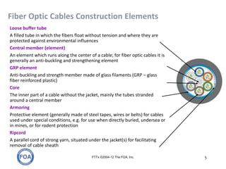


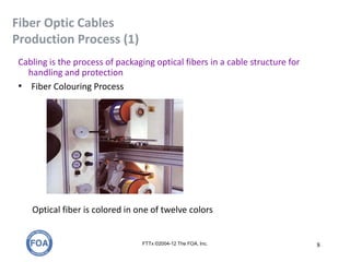


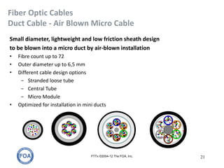
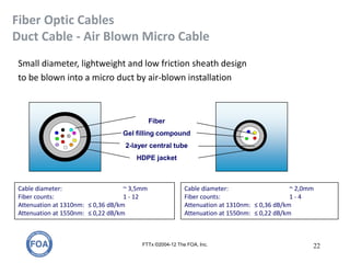
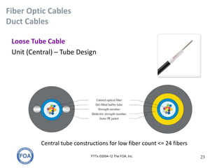

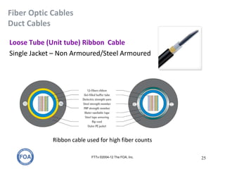


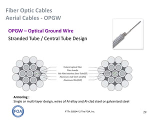


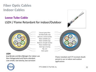

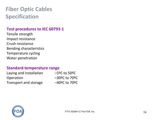


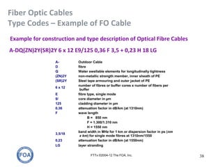


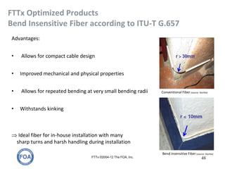


The document discusses fiber optic cable types and designs. It describes the various construction elements that make up fiber optic cables, including the fiber buffer, cable core, sheath, armor, and other protective elements. It also outlines the different cable construction types for outdoor, indoor, and special use cables. Finally, it provides details on the fiber optic cable production process and specifications.


