Downloaded 114 times


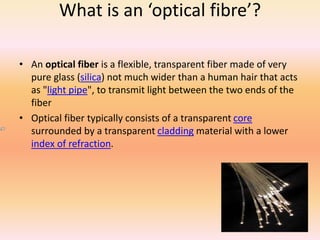
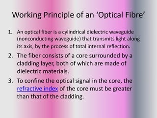
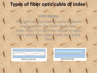
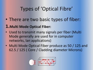
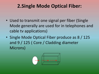
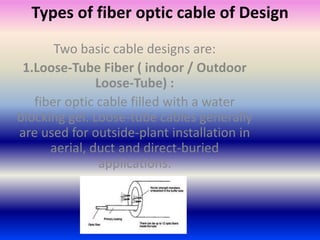

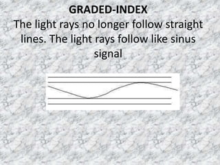
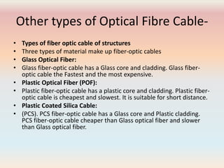


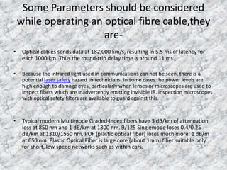
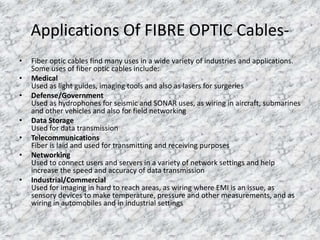


This document provides an overview of optical fibre cables. It defines an optical fibre as a flexible transparent fibre made of glass that transmits light through total internal reflection. Optical fibres can be classified based on mode of operation, design, index, and structure. The main types are multi-mode and single-mode fibres, with multi-mode used for shorter distances and local networks, and single-mode used for longer distance telecommunication networks. The document also discusses parameters to consider like attenuation and safety hazards when working with optical fibres, and applications in telecommunications, networking, medical and other industries.


