Download as PDF, PPTX


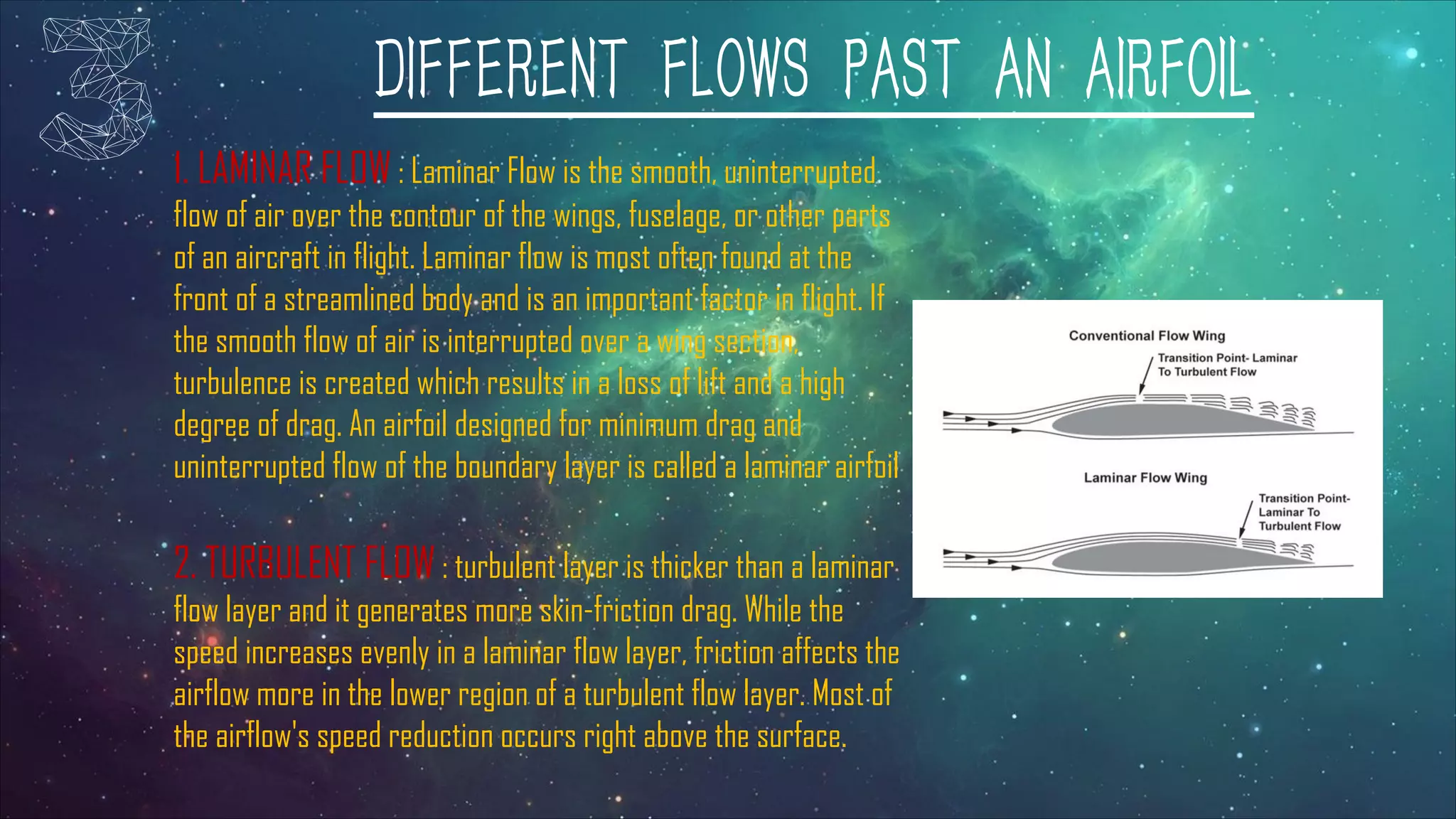
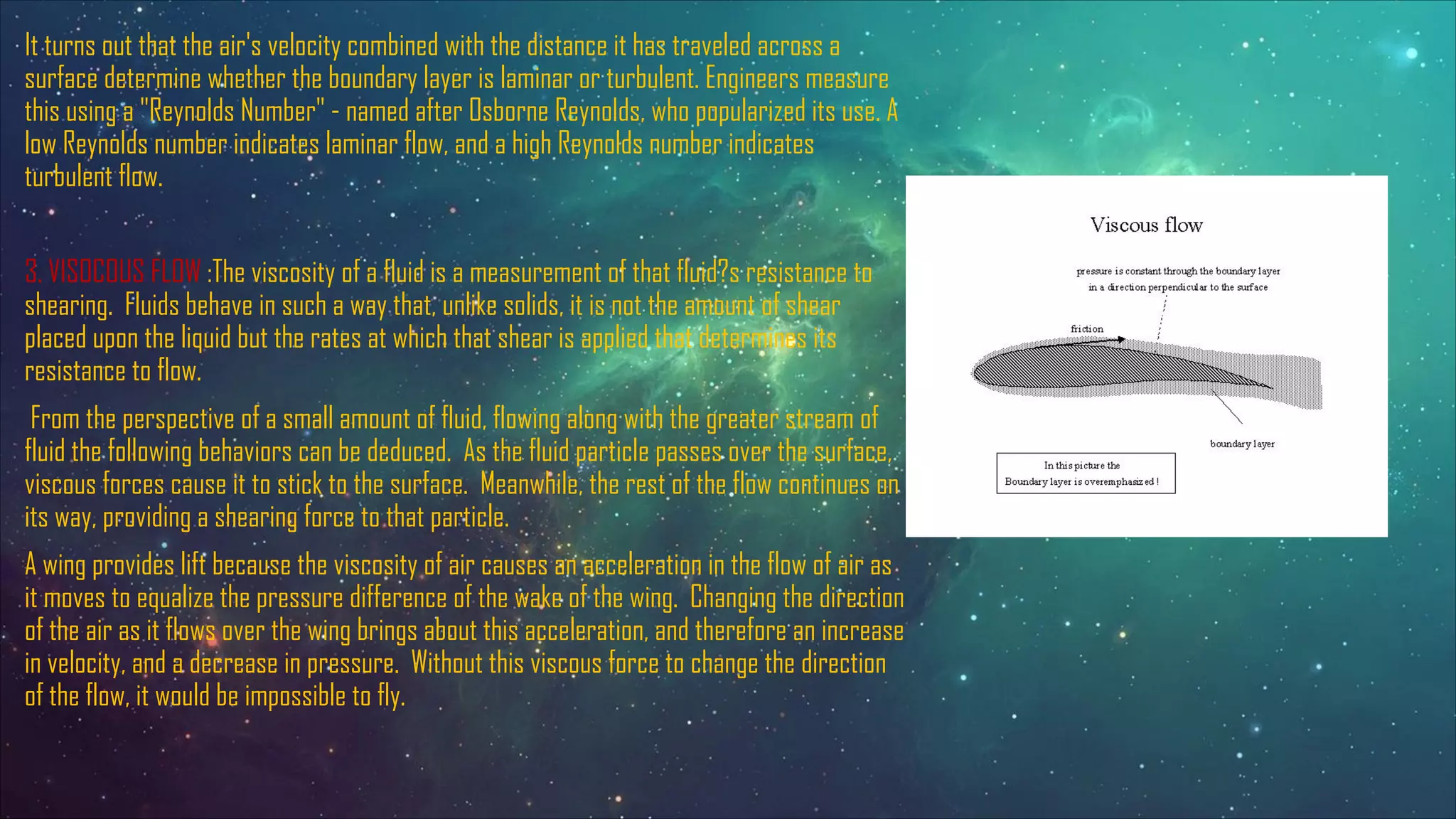
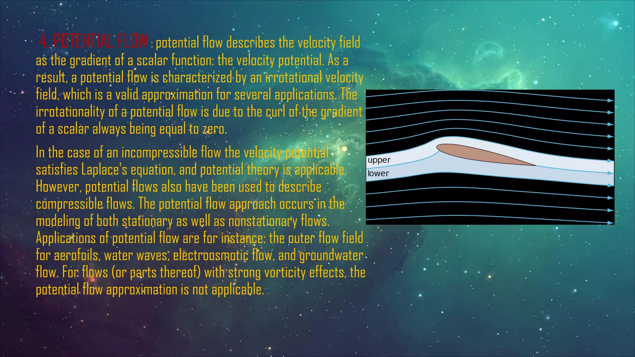


The document discusses the aerodynamics of airfoils, detailing their definitions, terminologies, types, and the principles of lift and drag. It explains the significance of flow characteristics such as laminar, turbulent, viscous, and potential flow in aerodynamics, along with the Kutta-Joukowski theorem for analyzing circulation and lift. Additionally, it highlights the role of viscosity in fluid behavior around airfoils, emphasizing the importance of maintaining smooth airflow for optimal performance.