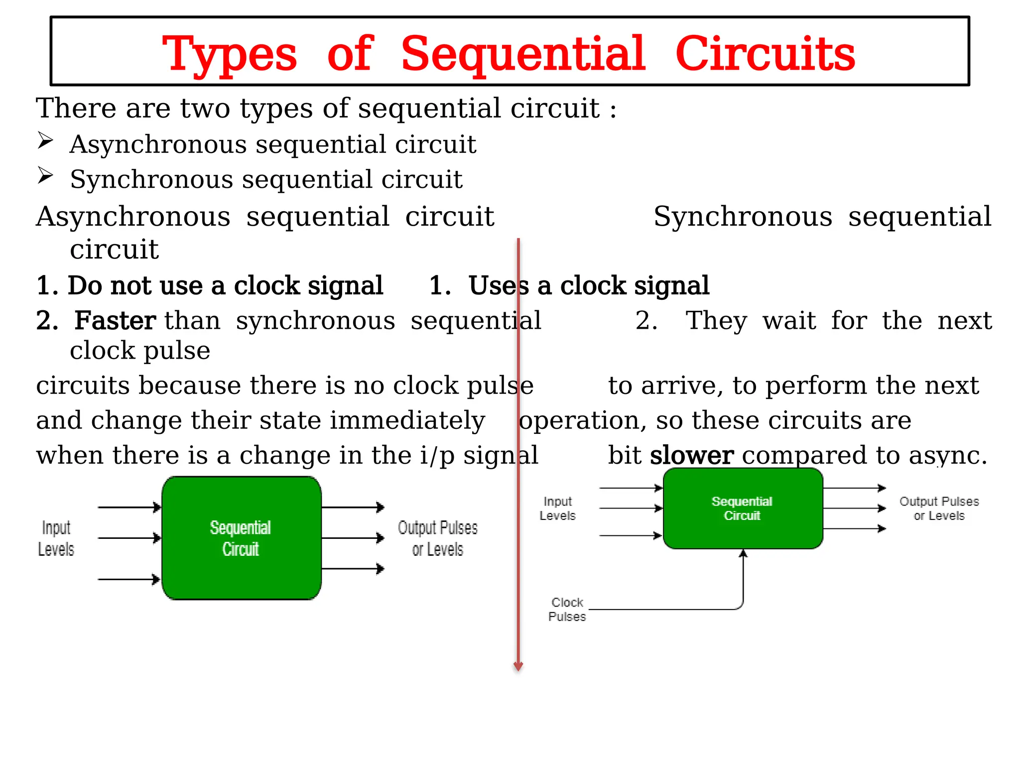
 Sequential logic circuits are a fundamental type of digital circuit where
the output depends not only on the current inputs but also on the
history of past inputs and outputs.
 This characteristic allows them to store information, which
distinguishes them from combinational logic circuits that rely solely
on current inputs.
Definition
 Sequential circuits incorporate memory elements, enabling them to
maintain a state based on previous inputs.
 This means the output at any given time is determined by both the
present inputs and the stored state from previous operations
UNIT - III
Sequential circuits
Combinational circuit
Combinational circuit:
• It produces an output based on present input variables
only
• The previous state of input does not have any effect on the
present state of the circuit
• The combinational circuit does not use any memory.
• Sequential circuit produces an output based on current
input and previous input variables.
Sequential circuit
Sequential circuit produces an output based on current
input and previous input variables.
A Sequential circuit combinational logic circuit that
consists of inputs variable (X), logic gates
(Combinational/Computational circuit), output variable
(Z) and Memory elements.
Combinational Circuits Sequential Circuits
1) The outputs of the combinational
circuit depend only on the present
inputs.
The outputs of the sequential circuits
depend on both present inputs and present
state(previous output).
2) The feedback path is not present in
the combinational circuit.
The feedback path is present in the
sequential circuits.
3) In combinational circuits, memory
elements are not required.
In the sequential circuit, memory elements
play an important role and require.
4) The clock signal is not required for
combinational circuits.
The clock signal is required for sequential
circuits.
5) The combinational circuit is simple to
design.
It is not simple to design a sequential
circuit.
Difference between the combinational circuits and sequential circuits
• The word “Sequential” means that things
happen in a “sequence”, one after
another.
• The clock signal actually determines
about the things will happen next.
• Simple sequential logic circuits can be
constructed from
standard Bistable circuits such as:
Flip lops, Latches and Counters
Types of Sequential Circuits
There are two types of sequential circuit :
 Asynchronous sequential circuit
 Synchronous sequential circuit
Asynchronous sequential circuit Synchronous sequential
circuit
1. Do not use a clock signal 1. Uses a clock signal
2. Faster than synchronous sequential 2. They wait for the next
clock pulse
circuits because there is no clock pulse to arrive, to perform the next
and change their state immediately operation, so these circuits are
when there is a change in the i/p signal bit slower compared to async.
 Flip-flops and latches are two kinds of memory circuits used in
electronics. The main difference between them is how they react to
changes.
 A latch changes its output whenever its input changes.
 A flip-flop only changes its output at specific moments, like when its
control signal goes from low to high.
 This makes flip-flops more stable in many situations.
 Latches are always alert to changes, while flip-flops only act at
certain times.
FLIP-FLOP & LATCHES
• Latch
• Flip flop
Memory Elements
Async. Sequential circuits
Sync. Sequential circuits
 Flip-flop is a basic digital memory circuit, which
stores one bit of information. Flip flops are the
fundamental blocks of most sequential circuits.
 It is also known as a bistable multivibrator or a
binary or one-bit memory. Flip-flops are used as
memory elements in sequential circuits.
 The output is obtained in a sequential circuit
from the Flip-flops combinational circuit or flip-
flop or both.
 The state of flip-flops changes at the active state
of clock pulses and remains unaffected when the
clock pulse is not active.
 In particular, clocked flip flops serve as memory
elements in synchronous sequential Circuits and
unclocked flip-flops (i.e., latches) serve as
memory elements in asynchronous sequential
circuits.
FLIP-FLOP
Applications of Flip-Flops
Flip-flops are edge-triggered devices that change state based on clock
signals. Their applications include:
 Counters: Flip-flops are widely used in digital counters, which
count events and display binary numbers in sequential order.
 Frequency Dividers: They can divide the frequency of an input
signal, which is crucial in various signal processing applications.
 Shift Registers: Flip-flops facilitate data transfer by temporarily
storing bits and allowing for series-parallel conversions.
 Data Storage: They act as basic memory units in digital
electronics, storing binary data until changed by input signals.
 Digital Systems: Flip-flops are integral to digital clocks, digital
door locks, and digital thermostats, where they manage and store
time-related data, security codes, and temperature settings
respectively.
 Control Logic: They are used in control systems to ensure
synchronization and proper functioning of digital circuits
 Latch is an electronic device, which changes its output immediately
based on the applied input.
 It is used to store either 1 or 0 at any specified time.
 It consists of two inputs namely “SET” and RESET and two outputs,
which are complement to each other.
LATCH
Latches are level-sensitive devices that maintain their state until the
input changes. Their applications include:
 Data Storage: Latches serve as memory elements that store
binary information, making them essential in various digital
circuits.
 Power Gating: Used to manage power consumption in electronic
devices by controlling the power supply to different components
based on the state of the latch.
 Asynchronous Systems: D latches are particularly useful in
systems where data needs to be stored without a clock signal,
such as input/output ports.
 Two-Phase Synchronous Systems: Latches help avoid transition
counts in data storage, ensuring smooth data flow during
operations.
 Pulse Latches: These latches behave similarly to flip-flops and
are used for generating quick responses in digital circuits
Applications of Latches
RS Latch
Storage Elements
• A storage element in a digital circuit can maintain a binary
state as long as power is delivered to the circuit
• It maintains state until directed by an input signal to
switch states.
Bistable circuit:
 A circuit which has two stable states.
.
.
.
.
A
B
.
.
X
Y
.
.
Latches
• Latches are basic storage elements that operate with
signal levels
• Latches are useful for the design of the asynchronous
sequential circuit.
• Latches are level-sensitive/ Level triggered devices.
• Triggering means making a circuit active.
• In level triggering the circuit will become active when the
gating / input is on a particular level.
Types of Latches:
• RS Latch
• D latch
RS Latch
Reset - Set Latch
• The SR (or) RS latch is a circuit with two cross-coupled
NOR gates or two cross-coupled NAND gates
• Two inputs labeled S for set and R for reset.
RS latch using NAND gates
RS latch using NOR gates
• RS Latch using NOR gates:
• Possible RS combinations are
R S Qp Qp’
0 0
0 1
1 0
1 1
A B Y
0 0 1
0 1 0
1 0 0
1 1 0
NOR truth
table
Qp is the Output (Present state)
Qp’ is the compl. of output
(Present state)
• Truth table for SR (or) RS latch using NOR gates
S R Qp Qp’ State
0 0 Qp Qp’ Memory / No change
state
0 1 0 1 RESET
1 0 1 0 SET
1 1 - - Invalid/ Forbidden
state
RS Latch using NAND gates:
A B Y
0 0 1
0 1 1
1 0 1
1 1 0
NAND truth
table
S R Qp State
0 0 Qp Invalid/ Forbidden
state
0 1 1 SET
1 0 0 RESET
1 1 - Memory / No change
state

Flipflop & Latches, RS Flipflop, NOR and NAND Gate Circuits

  • 1.
     Sequential logiccircuits are a fundamental type of digital circuit where the output depends not only on the current inputs but also on the history of past inputs and outputs.  This characteristic allows them to store information, which distinguishes them from combinational logic circuits that rely solely on current inputs. Definition  Sequential circuits incorporate memory elements, enabling them to maintain a state based on previous inputs.  This means the output at any given time is determined by both the present inputs and the stored state from previous operations UNIT - III Sequential circuits
  • 2.
    Combinational circuit Combinational circuit: •It produces an output based on present input variables only • The previous state of input does not have any effect on the present state of the circuit • The combinational circuit does not use any memory. • Sequential circuit produces an output based on current input and previous input variables.
  • 3.
    Sequential circuit Sequential circuitproduces an output based on current input and previous input variables. A Sequential circuit combinational logic circuit that consists of inputs variable (X), logic gates (Combinational/Computational circuit), output variable (Z) and Memory elements.
  • 4.
    Combinational Circuits SequentialCircuits 1) The outputs of the combinational circuit depend only on the present inputs. The outputs of the sequential circuits depend on both present inputs and present state(previous output). 2) The feedback path is not present in the combinational circuit. The feedback path is present in the sequential circuits. 3) In combinational circuits, memory elements are not required. In the sequential circuit, memory elements play an important role and require. 4) The clock signal is not required for combinational circuits. The clock signal is required for sequential circuits. 5) The combinational circuit is simple to design. It is not simple to design a sequential circuit. Difference between the combinational circuits and sequential circuits
  • 5.
    • The word“Sequential” means that things happen in a “sequence”, one after another. • The clock signal actually determines about the things will happen next. • Simple sequential logic circuits can be constructed from standard Bistable circuits such as: Flip lops, Latches and Counters
  • 6.
    Types of SequentialCircuits There are two types of sequential circuit :  Asynchronous sequential circuit  Synchronous sequential circuit Asynchronous sequential circuit Synchronous sequential circuit 1. Do not use a clock signal 1. Uses a clock signal 2. Faster than synchronous sequential 2. They wait for the next clock pulse circuits because there is no clock pulse to arrive, to perform the next and change their state immediately operation, so these circuits are when there is a change in the i/p signal bit slower compared to async.
  • 7.
     Flip-flops andlatches are two kinds of memory circuits used in electronics. The main difference between them is how they react to changes.  A latch changes its output whenever its input changes.  A flip-flop only changes its output at specific moments, like when its control signal goes from low to high.  This makes flip-flops more stable in many situations.  Latches are always alert to changes, while flip-flops only act at certain times. FLIP-FLOP & LATCHES
  • 8.
    • Latch • Flipflop Memory Elements Async. Sequential circuits Sync. Sequential circuits
  • 9.
     Flip-flop isa basic digital memory circuit, which stores one bit of information. Flip flops are the fundamental blocks of most sequential circuits.  It is also known as a bistable multivibrator or a binary or one-bit memory. Flip-flops are used as memory elements in sequential circuits.  The output is obtained in a sequential circuit from the Flip-flops combinational circuit or flip- flop or both.  The state of flip-flops changes at the active state of clock pulses and remains unaffected when the clock pulse is not active.  In particular, clocked flip flops serve as memory elements in synchronous sequential Circuits and unclocked flip-flops (i.e., latches) serve as memory elements in asynchronous sequential circuits. FLIP-FLOP
  • 10.
    Applications of Flip-Flops Flip-flopsare edge-triggered devices that change state based on clock signals. Their applications include:  Counters: Flip-flops are widely used in digital counters, which count events and display binary numbers in sequential order.  Frequency Dividers: They can divide the frequency of an input signal, which is crucial in various signal processing applications.  Shift Registers: Flip-flops facilitate data transfer by temporarily storing bits and allowing for series-parallel conversions.  Data Storage: They act as basic memory units in digital electronics, storing binary data until changed by input signals.  Digital Systems: Flip-flops are integral to digital clocks, digital door locks, and digital thermostats, where they manage and store time-related data, security codes, and temperature settings respectively.  Control Logic: They are used in control systems to ensure synchronization and proper functioning of digital circuits
  • 11.
     Latch isan electronic device, which changes its output immediately based on the applied input.  It is used to store either 1 or 0 at any specified time.  It consists of two inputs namely “SET” and RESET and two outputs, which are complement to each other. LATCH
  • 12.
    Latches are level-sensitivedevices that maintain their state until the input changes. Their applications include:  Data Storage: Latches serve as memory elements that store binary information, making them essential in various digital circuits.  Power Gating: Used to manage power consumption in electronic devices by controlling the power supply to different components based on the state of the latch.  Asynchronous Systems: D latches are particularly useful in systems where data needs to be stored without a clock signal, such as input/output ports.  Two-Phase Synchronous Systems: Latches help avoid transition counts in data storage, ensuring smooth data flow during operations.  Pulse Latches: These latches behave similarly to flip-flops and are used for generating quick responses in digital circuits Applications of Latches
  • 13.
  • 14.
    Storage Elements • Astorage element in a digital circuit can maintain a binary state as long as power is delivered to the circuit • It maintains state until directed by an input signal to switch states. Bistable circuit:  A circuit which has two stable states. . . . . A B . . X Y . .
  • 15.
    Latches • Latches arebasic storage elements that operate with signal levels • Latches are useful for the design of the asynchronous sequential circuit. • Latches are level-sensitive/ Level triggered devices. • Triggering means making a circuit active. • In level triggering the circuit will become active when the gating / input is on a particular level. Types of Latches: • RS Latch • D latch
  • 16.
    RS Latch Reset -Set Latch • The SR (or) RS latch is a circuit with two cross-coupled NOR gates or two cross-coupled NAND gates • Two inputs labeled S for set and R for reset. RS latch using NAND gates RS latch using NOR gates
  • 17.
    • RS Latchusing NOR gates: • Possible RS combinations are R S Qp Qp’ 0 0 0 1 1 0 1 1 A B Y 0 0 1 0 1 0 1 0 0 1 1 0 NOR truth table Qp is the Output (Present state) Qp’ is the compl. of output (Present state)
  • 18.
    • Truth tablefor SR (or) RS latch using NOR gates S R Qp Qp’ State 0 0 Qp Qp’ Memory / No change state 0 1 0 1 RESET 1 0 1 0 SET 1 1 - - Invalid/ Forbidden state
  • 19.
    RS Latch usingNAND gates: A B Y 0 0 1 0 1 1 1 0 1 1 1 0 NAND truth table S R Qp State 0 0 Qp Invalid/ Forbidden state 0 1 1 SET 1 0 0 RESET 1 1 - Memory / No change state