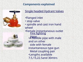
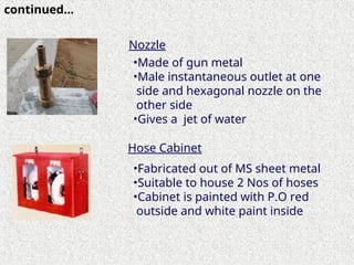
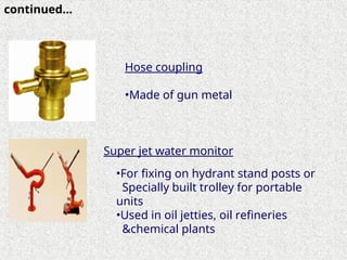
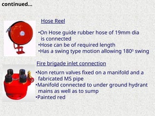
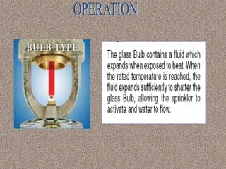
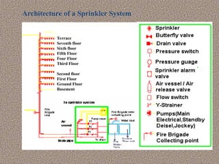
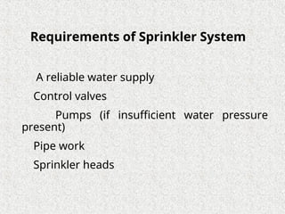
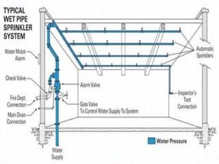
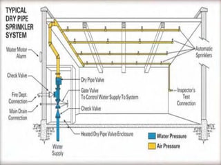
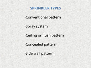
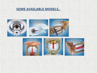
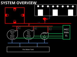
S A FE T Y
TELECOM
TURNKEY
VECAUN
P R O J E C T S
We Engineer Your Vision
Turnkey Contracts Division of
PS TECHCOM PVT LTD
HYDRANTS
&
SPRINKLERS
HYDRANTS
Fire Hydrant System, the oldest and still one
of the most effective fire fighting systems….
PURPOSE
The main function of a
hydrant is to supply
adequate water to
protect structure.
APPROVING AGENCIES
• National Fire Protection Association (N F P A)
• Tariff Advisory Committee (TAC)
• Oil Industry Safety Directorate (O I S D)
• Bureau of Indian Standards (BIS)
System Components For Hydrant
 Valves
 Hoses Reels
 Nozzles
 Hose Box
 Couplings
 Water Monitors
 Fire Brigade
 Pumps
Components explained
Single headed Hydrant Valves
•Flanged inlet
• stop valve
• spindle and cast iron hand
wheel
•Female instantaneous outlet
Fire fighting
Hose
•A flexible pipe with male
and on other
side with female
instantaneous type gun
Metal coupling pair
•Lengths available
7.5,15,22.5and 30mtrs
•Made of gun metal
•Male instantaneous outlet at one
side and hexagonal nozzle on the
other side
•Gives a jet of water
•Fabricated out of MS sheet metal
•Suitable to house 2 Nos of hoses
•Cabinet is painted with P.O red
outside and white paint inside
Nozzle
Hose Cabinet
continued…
Super jet water monitor
•For fixing on hydrant stand posts or
Specially built trolley for portable
units
•Used in oil jetties, oil refineries
&chemical plants
continued…
Hose coupling
•Made of gun metal
Hose Reel
•On Hose guide rubber hose of 19mm dia
is connected
•Hose can be of required length
•Has a swing type motion allowing 1800
swing
Fire brigade inlet connection
•Non return valves fixed on a manifold and a
fabricated MS pipe
•Manifold connected to under ground hydrant
mains as well as to sump
•Painted red
continued…
BASIC DESIGN RULES
HAZARD CLASSIFICATION LIGHT
ORDINARY
HIGH – A
HIGH – B
SPACING & LOCATION OF YARD HYDRANT 60M
45M
30M
PUMPING CAPACITY AS PER TAC, ON THE NUMBER OF HYDRANTS
TANK CAPACITY 1 HOUR – MIN 1.35 LAC LTRS
2 HOURS
3 HOURS
4 HOURS
Object
1
Object 2
Pump
house
Building
1
Building2
INTERNAL HYDRANT
1. Landing Valves provided on
each floor.
2. Usually Located within fire
access lobbies, protected
staircases or protected
lobbies.
3. Hose Boxes may be provided
to protect Landing Valves.
4. 2 Hose reel of 7.5 Mtrs Length.
PUMPING FACILITY ,HEART OF FIRE HYDRANT SYSTEM
• Electrical pump
 builds pressure
 pumps water in normal condition
 automatic on ,manual off
• Diesel pump (standby )
 pumps water during main failure
 automatic on ,manual off
• Jockey pump
 for building pressure
 automatic on , automatic off
PUMP HOUSE
PUMP HOUSE
SYSTEM OVERVIEW
Diesel
Fire
Water
Pump
Elec.
Fire
Water
Pump
Jocke
y
Pum
p
PS
MCC
PAN
EL
PS
PS
Fire Water Tank
A sprinkler system consists of a water supply (or supplies)
and one or more sprinkler installations, each installation
consist of a set of installation control valves and a pipe
array fitted with sprinkler heads. The sprinkler heads are
fitted at specified locations at the roof or ceiling, and
where necessary between racks, below shelves, inside
ovens or stoves or below obstructions.
A sprinkler has two functions to perform. It must first
sense the heat, and must then provide an adequate
distribution of water to control or extinguish the fire.
Each function is performed separately and one is
independent of the other except insofar as early detection
makes extinction easier because the fire has not grown
large. The classic use of the sprinkler is in the hot gas
layer which forms beneath the ceiling of an enclosure in
which a fire is developing.
SPRINKLER SYSTEM
Applications
Terrace
Seventh floor
Sixth floor
Fifth Floor
Four Floor
Third Floor
Second floor
First Floor
Ground Floor
Basement
Architecture of a Sprinkler System
Requirements of Sprinkler System
A reliable water supply
Control valves
Pumps (if insufficient water pressure
present)
Pipe work
Sprinkler heads
TYPES OF SPRINKLER SYSTEM
o Dry-pipe sprinkler installations
o Wet-Pipe Sprinkler Systems
o Pre-action Sprinkler Systems
o Deluge System
o Combined Dry Pipe-pre-action System
A sprinkler system employing automatic
sprinklers attached to a piping system containing
air that may or may not be under pressure, with a
supplemental detection system installed in the
same areas as the sprinklers. Actuation of the
detection system opens a valve that permits
water to flow into the sprinkler piping system and
to be discharged from any sprinklers that are
open.
Pre-action System
Combined Dry Pipe-Pre-action System
A sprinkler system employing automatic sprinklers
attached to a piping system containing air under pressure,
with a supplemental detection system installed in the
same areas as the sprinklers. Operation of the detection
system actuates the tripping devices that open dry pipe
valves simultaneously and without loss of air pressure in
the system. Operation of the detection system also opens
listed air exhaust valves at the end of feed main, which
usually precedes the opening of sprinklers. The detection
system also serves as an automatic fire alarm system..."
(NFPA 13)
A sprinkler system employing open
sprinklers attached to a water supply
through a valve that is opened by the
operation of a detection system installed in
the same areas as the sprinklers. When
this valve opens, water flow into the piping
system and discharges from all sprinklers
attached thereto.
Deluge System.
SPRINKLER TYPES
•Conventional pattern
•Spray system
•Ceiling or flush pattern
•Concealed pattern
•Side wall pattern.
SOME AVAILABLE MODELS..
GOVERNING BODIES
BASIC DESIGN RULES
Design density to be chosen as per the hazard
Area is divided into zones based on the flow
required
Sprinklers are heat sensitive (58o
C) for indoor
applications
Pressure at the sprinkler to be maintained
between 1.5 bars to 3.5 bars
Velocity to be maintained in the pipes below 5 m/s
Pressure Calculation to be based on Hazen
William’s formula
Based on TAC Rules for Sprinkler Systems
SYSTEM OVERVIEW
Diesel
Fire
Water
Pump
Elec.
Fire
Water
Pump
Jocke
y
Pum
p
PS
MCC
PAN
EL
PS
PS
Fire Water Tank
Thank You

Hydrant & Sprinkler System design and .ppt

  • 1.
    S A FET Y TELECOM TURNKEY VECAUN P R O J E C T S We Engineer Your Vision Turnkey Contracts Division of PS TECHCOM PVT LTD
  • 2.
  • 3.
    HYDRANTS Fire Hydrant System,the oldest and still one of the most effective fire fighting systems….
  • 4.
    PURPOSE The main functionof a hydrant is to supply adequate water to protect structure.
  • 5.
    APPROVING AGENCIES • NationalFire Protection Association (N F P A) • Tariff Advisory Committee (TAC) • Oil Industry Safety Directorate (O I S D) • Bureau of Indian Standards (BIS)
  • 6.
    System Components ForHydrant  Valves  Hoses Reels  Nozzles  Hose Box  Couplings  Water Monitors  Fire Brigade  Pumps
  • 7.
    Components explained Single headedHydrant Valves •Flanged inlet • stop valve • spindle and cast iron hand wheel •Female instantaneous outlet Fire fighting Hose •A flexible pipe with male and on other side with female instantaneous type gun Metal coupling pair •Lengths available 7.5,15,22.5and 30mtrs
  • 8.
    •Made of gunmetal •Male instantaneous outlet at one side and hexagonal nozzle on the other side •Gives a jet of water •Fabricated out of MS sheet metal •Suitable to house 2 Nos of hoses •Cabinet is painted with P.O red outside and white paint inside Nozzle Hose Cabinet continued…
  • 9.
    Super jet watermonitor •For fixing on hydrant stand posts or Specially built trolley for portable units •Used in oil jetties, oil refineries &chemical plants continued… Hose coupling •Made of gun metal
  • 10.
    Hose Reel •On Hoseguide rubber hose of 19mm dia is connected •Hose can be of required length •Has a swing type motion allowing 1800 swing Fire brigade inlet connection •Non return valves fixed on a manifold and a fabricated MS pipe •Manifold connected to under ground hydrant mains as well as to sump •Painted red continued…
  • 11.
    BASIC DESIGN RULES HAZARDCLASSIFICATION LIGHT ORDINARY HIGH – A HIGH – B SPACING & LOCATION OF YARD HYDRANT 60M 45M 30M PUMPING CAPACITY AS PER TAC, ON THE NUMBER OF HYDRANTS TANK CAPACITY 1 HOUR – MIN 1.35 LAC LTRS 2 HOURS 3 HOURS 4 HOURS
  • 12.
  • 13.
    INTERNAL HYDRANT 1. LandingValves provided on each floor. 2. Usually Located within fire access lobbies, protected staircases or protected lobbies. 3. Hose Boxes may be provided to protect Landing Valves. 4. 2 Hose reel of 7.5 Mtrs Length.
  • 14.
    PUMPING FACILITY ,HEARTOF FIRE HYDRANT SYSTEM • Electrical pump  builds pressure  pumps water in normal condition  automatic on ,manual off • Diesel pump (standby )  pumps water during main failure  automatic on ,manual off • Jockey pump  for building pressure  automatic on , automatic off
  • 15.
  • 16.
  • 17.
    A sprinkler systemconsists of a water supply (or supplies) and one or more sprinkler installations, each installation consist of a set of installation control valves and a pipe array fitted with sprinkler heads. The sprinkler heads are fitted at specified locations at the roof or ceiling, and where necessary between racks, below shelves, inside ovens or stoves or below obstructions. A sprinkler has two functions to perform. It must first sense the heat, and must then provide an adequate distribution of water to control or extinguish the fire. Each function is performed separately and one is independent of the other except insofar as early detection makes extinction easier because the fire has not grown large. The classic use of the sprinkler is in the hot gas layer which forms beneath the ceiling of an enclosure in which a fire is developing. SPRINKLER SYSTEM
  • 18.
  • 20.
    Terrace Seventh floor Sixth floor FifthFloor Four Floor Third Floor Second floor First Floor Ground Floor Basement Architecture of a Sprinkler System
  • 21.
    Requirements of SprinklerSystem A reliable water supply Control valves Pumps (if insufficient water pressure present) Pipe work Sprinkler heads
  • 22.
    TYPES OF SPRINKLERSYSTEM o Dry-pipe sprinkler installations o Wet-Pipe Sprinkler Systems o Pre-action Sprinkler Systems o Deluge System o Combined Dry Pipe-pre-action System
  • 25.
    A sprinkler systememploying automatic sprinklers attached to a piping system containing air that may or may not be under pressure, with a supplemental detection system installed in the same areas as the sprinklers. Actuation of the detection system opens a valve that permits water to flow into the sprinkler piping system and to be discharged from any sprinklers that are open. Pre-action System
  • 26.
    Combined Dry Pipe-Pre-actionSystem A sprinkler system employing automatic sprinklers attached to a piping system containing air under pressure, with a supplemental detection system installed in the same areas as the sprinklers. Operation of the detection system actuates the tripping devices that open dry pipe valves simultaneously and without loss of air pressure in the system. Operation of the detection system also opens listed air exhaust valves at the end of feed main, which usually precedes the opening of sprinklers. The detection system also serves as an automatic fire alarm system..." (NFPA 13)
  • 27.
    A sprinkler systememploying open sprinklers attached to a water supply through a valve that is opened by the operation of a detection system installed in the same areas as the sprinklers. When this valve opens, water flow into the piping system and discharges from all sprinklers attached thereto. Deluge System.
  • 28.
    SPRINKLER TYPES •Conventional pattern •Spraysystem •Ceiling or flush pattern •Concealed pattern •Side wall pattern.
  • 29.
  • 30.
  • 31.
    BASIC DESIGN RULES Designdensity to be chosen as per the hazard Area is divided into zones based on the flow required Sprinklers are heat sensitive (58o C) for indoor applications Pressure at the sprinkler to be maintained between 1.5 bars to 3.5 bars Velocity to be maintained in the pipes below 5 m/s Pressure Calculation to be based on Hazen William’s formula Based on TAC Rules for Sprinkler Systems
  • 32.
  • 33.