This document is a thesis submitted for the degree of Bachelor of Technology in Electronics and Communication Engineering at Maulana Abul Kalam Azad University of Technology. It describes the development of a GPS enabled location tracking digital band by a group of five students - Aditi, Akash Shaw, Dona Chakraborty, Durba Kundu, and Subhrojyoti Das - under the supervision of Prof. Tarun Kumar Das at Future Institute of Engineering & Management. The thesis includes certificates of recommendation, approval, acknowledgement, index, and literature survey sections. It aims to design a wireless and portable location tracking system using a microcontroller interfaced with a GPS module and Bluetooth to allow caregivers
This document provides an overview of smart antennas. It begins with a brief history, noting that smart antennas were initially developed for military communications and intelligence gathering. The document defines smart antennas as antenna arrays that can adaptively change their pattern in response to signal environments to improve communication channel performance. It describes the key components and functioning of smart antennas, including digital beamforming and direction of arrival estimation techniques. The main types of smart antennas are explained as adaptive array antennas and switched beam array antennas. Advantages like reduced interference and increased capacity are outlined. Applications in mobile communications, satellites, and wireless networks are also mentioned.
innovative railway track surveying with sensors and controlled by wireless co...kalaimathi mathiyazhagan
This document describes a proposed multi-sensor railway track geometry surveying system. The system uses MEMS, ultrasonic, and GPS sensors on a robot to detect cracks and obstacles on railway tracks and bridges in real-time. When issues are detected, the GPS location is recorded and an SMS is sent to authorities via GSM. Trains approaching will also receive a wireless message to slow down. A microcontroller controls gate closures to prevent accidents. The low-cost system aims to improve safety by allowing for faster response times over existing manual inspection methods.
RFID based smart shopping cart and billing systemlaharipothula
To make the shopping easy by automated billing at the shopping mall/ super maeket. This module mainly cocnsists of Arduino, RFID tags & reader and zigbee module.
1. The document lists over 100 potential seminar topics in computer science and information technology, ranging from embedded systems and extreme programming to biometrics, quantum computing, and more.
2. Some examples include elastic quotas, electronic ink, gesture recognition, graphics processing units, grid computing, and honeypots.
3. The broad range of topics provide many options for students or professionals to explore emerging technologies and issues in computing.
This document provides a summary of smart glasses technologies. It begins with an introduction to smart glasses and their basic functions. It then compares smart glasses to previous technologies, noting limitations such as short battery life and occasional use. The document outlines several display technologies used in smart glasses and lists their key features. It discusses potential healthcare applications and uses for documentation, productivity, and assisting blind or visually impaired individuals. In closing, it examines the advantages and disadvantages of smart glasses as well as future development plans.
IoT Based Garbage Monitoring System pptRanjan Gupta
This document presents an IOT-based garbage monitoring system that uses ultrasonic sensors and a microcontroller to detect garbage levels in bins. The system sends this data over WiFi to a web page that graphically displays the garbage levels in each bin in real-time. When a bin reaches capacity, the system alerts municipal workers to empty it. This innovative system aims to help keep cities clean and support initiatives like Swachh Bharat Mission by optimizing garbage collection.
This device is very useful for the people who surfering with eye blindness and this can able to detect the obstacles with the help of ultrasonic sensor.
The smart blind stick is an assistive device that uses ultrasonic sensors and a microcontroller to help blind people navigate and detect obstacles. It contains an 8051 microcontroller, ultrasonic sensor, buzzer, and power supply. The microcontroller is programmed using C language to detect obstacles and alert the user with audible signals from the buzzer. It can help blind people walk safely and avoid obstacles by auto-detecting the surroundings and providing turn and obstacle alerts. Future improvements could include adding GPS for navigation assistance and GSM for emergency calls.
Locker opening and closing system using rfid password and gsmSai Kumar
This document describes a locker opening and closing system using RFID, password, and GSM technology. The system is designed to increase security for bank lockers, secured offices, and homes. It uses an RFID reader to read a tag's ID number and send it to a microcontroller. The microcontroller then sends a password to an authenticated person's phone. That person must enter both passwords received to unlock the door. If the passwords do not match, a warning is sent and the door remains locked, providing improved security over existing manual and digital systems.
Alcohol Detection System in Vehicle using ArduinoIRJET Journal
This paper describes a system to detect alcohol in a vehicle using an Arduino board, an MQ3 alcohol sensor, an LCD display and a buzzer. The system is installed in a vehicle and uses the alcohol sensor to detect alcohol levels in a person's breath when they enter the vehicle. If alcohol is detected, the buzzer sounds and a message is displayed on the LCD. The system is designed to prevent accidents caused by drunk driving by automatically shutting off the vehicle's ignition if alcohol is present. The paper provides details of the hardware components used, including the Arduino board, alcohol sensor and LCD display. It also includes the system workflow, advantages and potential applications of the system.
1) This project presents an automatic room light controlling system using an 8051 microcontroller and two infrared sensors that detects movement to turn lights on when someone enters and off when the last person leaves.
2) The system is designed to count the number of visitors entering and leaving to determine when to turn the lights on and off.
3) When a person enters they are detected by the outer sensor first, then the inner sensor, turning on the lights and incrementing the counter. Lights remain on and counter increments until the last person leaves.
WIMAX stands for Worldwide Interoperability for Microwave Access.WiMAX refers to broadband wireless networks that are based on the IEEE 802.16 standard, which ensures compatibility and interoperability between broadband wireless access equipment.
This document describes a password based door locking security system presented by four students. The system uses a microcontroller, keypad, LCD display, buzzer, DC motor, and other components. It allows a user to enter a password to open the door for security and can be used to secure doors, lockers, and other areas. The system was tested and provides advantages like automatic door opening and indication of unauthorized entry while being cost efficient.
This project aims to develop an IoT-based smart garbage monitoring system using an Arduino board, ultrasonic sensor, GSM module, and cloud platform. The system monitors garbage bin levels and alerts municipal authorities via SMS when bins are full to help keep the environment clean and hygienic. It works by using an ultrasonic sensor to detect waste levels in bins and sending data to a cloud server, then alerts are triggered to responsible parties if the bin exceeds a threshold level. This automatic monitoring system helps address issues of overflowing bins and improves sanitation.
IoT Based Garbage Monitoring System pptRanjan Gupta
1) A group of students presented on an IOT Garbage Monitoring System to help keep cities clean.
2) The system uses ultrasonic sensors and a microcontroller to monitor garbage levels in bins and displays the status on an LCD screen and web page.
3) When fully implemented, the system will help support initiatives like Swachh Bharat Mission by enabling real-time garbage monitoring and efficient collection.
This document describes the design and fabrication of a microelectronic pill used for remote biomedical measurements. It contains four sensor chips that measure temperature, pH, conductivity, and dissolved oxygen levels. Chip 1 contains a temperature diode, pH ISFET sensor, and conductivity electrodes. Chip 2 contains an oxygen sensor and optional thermometer. The sensors were fabricated using microfabrication techniques like photolithography and electron beam lithography. An application-specific integrated circuit controls the sensors and transmits the sampled multi-channel data wirelessly to an external receiver for analysis. The microelectronic pill is aimed to enable non-invasive physiological analysis of the gastrointestinal tract to detect diseases and abnormalities.
PROJECT REPORT ON Home automation using by BluetoothAakashkumar276
This document summarizes a student project on developing a home automation system using an Arduino board and Bluetooth. The system allows users to control electrical appliances like fans and lights in their home remotely using an Android phone app. The app communicates with an Arduino Uno microcontroller via HC-05 Bluetooth module. The Arduino is connected to a 4-channel relay board to switch appliances on and off. The project aims to provide a low-cost solution for remote home control without needing physical switches or remote controls.
This document describes the design and implementation of a radar system using an Arduino. The system uses an Arduino Uno, ultrasonic sensor, servo motor, and other components to detect objects. It provides advantages such as seeing through fog or darkness and determining an object's range, position, and velocity. Limitations include not being able to distinguish close targets or recognize color. The system was created to learn about radar technology and demonstrate its uses and capabilities.
Smart cameras capture high-level descriptions of a scene and perform real-time analysis of what they see. These low-cost, low-power systems push the design space in many dimensions, making them a leading-edge
application for embedded system research.
The document discusses wireless charging for mobile phones. It introduces wireless charging and its benefits over wired charging. Wireless charging works through magnetic resonance using a transmitter coil to generate a magnetic field and a receiver coil to convert it to electric current. There are three main types of wireless charging: resonant charging using tuned coils, radio charging using radio waves, and inductive charging using electromagnetic induction. Wireless charging allows for more convenient charging of devices without physical connections.
The document proposes a method for wirelessly charging batteries using microwaves. It notes that current wireless charging methods require devices to be placed on charging plates, which can be inconvenient while traveling. The proposed method would allow electronic devices to charge as they are being used through harnessing leftover microwave radiation from cellular networks. Charging would work on the same principle as a microwave oven, using microwaves to heat the batteries and provide power. This could both charge devices conveniently during use and reduce hazardous health effects from excess radiation.
The document describes a simulation project for a communication link using AM and PSK modulation. Students are asked to design and simulate a communication link using AM modulation to transmit an audio signal, investigating the effects of different message signal frequencies and modulation indices. They also simulate communication links using BPSK and QPSK modulation schemes, comparing the performance of each in terms of bandwidth efficiency and required signal power. The project uses Matlab and Simulink to generate signals, design modulators and demodulators, and simulate the overall communication links.
The aim of this project is to control the electrical appliances through a personal computer (PC). With this system, one can control the electrical appliances ON/OFF by just being seated at one place using a PC.
Smart street lighting control system project PPT PetchiMuthu26
This document contains details about a smart street light control system project. It lists the batch members and project guide. The objectives are to reduce energy consumption and inform authorities about any incidents or street light faults using sensors, a camera and GSM modem. It describes the components used like PIR sensor, vibration sensor, camera, microcontroller. It also explains how ThingSpeak cloud platform can be used to store and access real-time sensor data through mobile phones.
here we controller an robot car through the internet using wifi module connected to the microcontroller, that sends the data and receives the data according to data the car movies and the car has been attached a camera which is used to record videos or take pictures or live streaming
IRJET- Bemythirdeye- A Smart Electronic Blind Stick with GogglesIRJET Journal
This document describes a smart electronic blind stick designed to help visually impaired people navigate independently and safely. The stick uses various sensors like ultrasonic sensors, IR sensors, and a PIR motion sensor to detect obstacles, motion, and staircases. It alerts the user with a buzzer when obstacles are detected. It also includes a location tracking module using GPS and GSM to send the user's location to contacts in emergencies. The stick is controlled with a microcontroller and aims to provide more accurate detection than traditional blind sticks by combining multiple sensor types. It allows visually impaired users to navigate with greater confidence, safety, and independence.
F B ASED T ALKING S IGNAGE FOR B LIND N AVIGATIONIJCI JOURNAL
The major challenge of visually impaired person is
in mobility, object identification and identificati
on of
space around him/her. The proposed RF Based Talking
Signage for Blind Navigation aims to provide a
universal electronic travel guide for the visually
challenged people. This system incorporates a user
friendly and versatile method called “Talking Signa
ge” that is implemented using android devices. The
system uses an Android application in the mobile ph
one which could deliver voice messages about the us
er
environment via a heterogeneous network. It can be
deployed in any dense environment so that blind
persons can fulfill their needs. The primary advant
age of the system compared to other system in the a
rea is
low cost, ease of transport, less power consumption
, lightweight, and it could be utilized by those pe
oples
who are technically challenged. The architecture pr
oposed in this paper clearly shows communication
between a mobile phone and a heterogeneous network
enabled with RF devices. We have implemented the
system in our university environment and the propos
ed system found to be a great success
1. The document describes a smart blind stick that uses sensors and a voice module to help visually impaired people navigate independently.
2. It uses ultrasonic sensors to detect obstacles and a water sensor to detect water or puddles. When obstacles or water are detected, the voice module provides audio warnings to the user.
3. An RF remote is also included to help users locate the stick if they misplace it. The stick aims to provide cost-effective navigation assistance and obstacle detection to enhance mobility and independence for the visually impaired.
GPS & GSM based Voice Alert System for Blind Personijsrd.com
This paper presents a theoretical model and a system concept to provide a smart electronic aid for blind people. This system is intended to provide overall measures –object detection and real time assistance via Global Positioning System (GPS).The system consist of ultrasonic sensor, GPS Module, GSM Module and vibratory circuit (speakers or head phones). This project aims at the development of an Electronic Travelling Aid (ETA) kit to help the blind people to find obstacle free path. This ETA is fixed to the stick of the blind people. When the object is detected near to the blinds stick it alerts them with the help of vibratory circuit (speakers or head phones). The location of the blind is found using Global System for Mobile communications (GSM) and Global Position System (GPS).
Blind Stick Using Ultrasonic Sensor with Voice announcement and GPS trackingvivatechijri
for blind individuals. Basically, the ultrasonic detector is enforced within the walking stick for detection the obstacles ahead of the blind/impaired persons. If there are any obstacles, it'll alert the blind man to avoid that obstacles and therefore the alert in Our project proposes a low-priced walking stick supported latest technology and a brand-new implementation are created for economical interface the shape of voice announcement and buzzer to form a lot of helpful the stick is additionally mounted with the water detector that detects and alerts the blind if any wetness content is present to avoid slippery methods. Daily in several aspects so as to produce versatile and safe movement for the individuals. During this technology driven world, wherever individuals try to measure severally, this project propose a low-priced stick for blind individuals to achieve personal independence, in order that they will move from one place to a different simply and safely. A conveyable stick is style and developed that detects the obstacles within the path of the blind using sensors. The buzzer and vibration motor are activated once any obstacle is detected. Additionally, the stick is provided with GPS and SMS message system. GPS system give the knowledge relating to the situation of the blind man using the stick with his relations. SMS system is employed by the blind to send SMS message to the saved numbers within the microcontroller just in case of emergency.
This document describes a smart walking stick designed to assist blind people by detecting obstacles and potholes using ultrasonic sensors. The stick is connected to an Android application via Bluetooth to provide auditory feedback to the user. Ultrasonic sensors detect obstacles and determine the closest safe path. Additional sensors check the ground clearance to identify potholes. The application allows navigation to locations via voice commands and calling pre-set emergency contacts using hand gestures. The system aims to help blind individuals move independently and safely.
GPS and GSM enabled Smart Blind Stick.pdfssuserbfa471
The document proposes a GPS and GSM enabled smart blind stick that uses sensors like ultrasonic sensors, infrared sensors, and a pulse sensor integrated with a microcontroller and notification systems like buzzers and GPS/GSM modules. This is aimed to help visually impaired people navigate safely and also send emergency alerts. The system detects obstacles and changes in pulse rate using sensors and alerts the user or emergency contacts using buzzers or text messages with the person's location. A prototype was developed and simulations showed it could reliably detect surroundings and send notifications to improve assistance for visually impaired individuals.
Design and implementation of smart guided glass for visually impaired peopleIJECEIAES
The objective of this paper is to develop an innovative microprocessor-based sensible glass for those who are square measure visually impaired. Among all existing devices in the market, one can help blind people by giving a buzzer sound when detecting an object. There are no devices that can provide object, hole, and barrier information associated with distance, family member, and safety information in a single device. Our proposed guiding glass provides all that necessary information to the blind person’s ears as audio instructions. The proposed system relies on Raspberry pi three model B, Pi camera, and NEO-6M global positioning system (GPS) module. We use TensorFlow and faster region-based convolutional neural network (R-CNN) approach for detection of objects and recognition of family members of the blind man. This system provides voice information through headphones to the ears of the blind person, and facile the blind individual to gain independence and freedom within the indoor and outdoor atmosphere.
Smart Cane for Blind Person Assisted with Android Application and Save Our So...Dr. Amarjeet Singh
Today technology is improving daily in different
aspects in order to provide flexible proposes Smart Cane
(Stick) for blind person. But there is no such kind of good
system to navigate a blind person and help in emergency
situation. In this paper, user friendly device is proposed that
can identify the obstacles in the path using ultrasonic sensors.
In this system blind person will navigated through a cane
interfaced with an android application. A blind person can
establish voice call or SMS to a predefined number just by
pressing the emergency button on cane using GSM module. In
addition, people will get notified as Facebook status updated
with emergency alert. This system develop an android
application which is smart and user-friendly. While walking
in public place during night time, the blind person can use
cane as a flashlight which illuminates automatically.
DRISHTI – A PORTABLE PROTOTYPE FOR VISUALLY IMPAIREDIRJET Journal
This document describes a portable prototype called Drishti that aims to help visually impaired people navigate more easily. It uses ultrasonic sensors to detect nearby obstacles and notifies the user through vibrations. It also includes GPS and GSM modules to track the user's live location and send it to a caretaker via SMS. The goal is to provide a cheaper and more efficient alternative to traditional canes or guide dogs. It was designed to be worn like cloth and uses ultrasonic waves, vibrations and location tracking to help visually impaired people navigate with greater speed, comfort and confidence.
Intelligent travelling and home automation aid, for visually impairedUmar Shuaib
The document describes the design and development of an intelligent electronic travelling aid called IETA-VI for visually impaired individuals. The system uses ultrasonic detection to detect obstacles and converts distances to voice messages. It uses GPS and GSM technologies to determine the user's location and send it to caregivers. The device can also recognize voice distress signals, send the user's location via SMS, and has an emergency button to alert caregivers. The system aims to help visually impaired people navigate independently.
Design and development of intelligent electronics travelling aid for visually...eSAT Journals
Abstract The dynamic nature of the environment poses a big challenge to the visually impaired in navigation. This compels most of the visually impaired persons in the developing countries, who generally do not get any technology support, to depend on the visual sense of others, thus, undermining their independence. The intelligent electronic travelling aid for the visually impaired (IETA-VI) designed and developed by the authors and reported here, intends to provide solution to the navigational challenges of the visually impaired individuals. The system utilizes the ultrasonic detection technology for detecting any obstacle in his/her path, and then converts the distance to the obstacle into voice using voice synthesis technology so as to inform the visually impaired user. The device uses GPS and GSM technologies to determine the location of the user and to send this location to his/her care givers on mobile phone, respectively. The device also recognizes the voice signals of the visually impaired when in distress, by making use of voice recognition technology and send SMS to his care givers giving his location and asking them to help him. In a moment of emergency, when the visually impaired requires the attention of his/her care givers, the device provides three alternatives: The first alternative it provides is an emergency key, which when pressed will automatically send the location of the visually impaired to the care givers. The second alternative is that the visually impaired shouts (gives a voice command), the device responds by sending the location of the visually impaired to the care givers. The third alternatives take care of the situation when the user is unconscious or cannot even speak. This is provided by the display device, which displays the names and contact details of his/her care givers, so that someone can offer a helping hand. KEYWORDS: Ultrasonic detection, Voice recognition, Voice synthesis, GPS, GSM.
Design and Implementation of Ultrasonic Navigator for Visually ImpairedDr.SHANTHI K.G
The document describes the design and implementation of an ultrasonic navigator device to help visually impaired people navigate their environment. The device uses ultrasonic sensors to detect obstacles in the environment and servo motors mounted on a glove to provide haptic feedback to the user about the distance and direction of obstacles. It also includes a GPS system to provide navigation instructions to help users reach their destinations. The device aims to provide more information about obstacles than a traditional walking cane by detecting objects in multiple directions and at distances over 1 meter.
The document describes a proposed smart ID system for blind individuals to aid in navigation. The system would use sensors like IR sensors, ultrasonic sensors and a GPS module to detect objects and the user's location. It would provide auditory and vibratory feedback to inform the user about obstacles. If an emergency occurs, a panic button could send a notification with the user's location and image to contacts via email and text. The system aims to allow blind people to navigate independently and safely.
IRJET- Smart Assistive Device for Visually ImpairedIRJET Journal
This document describes the development of a smart assistive device for visually impaired individuals. The device uses an ultrasonic sensor to detect obstacles and provide haptic or audio feedback to warn the user of obstacles in their path. It is powered by a lithium ion battery and processed using an Arduino microcontroller. Testing showed that visually impaired individuals could use the device to safely navigate an environment and avoid collisions with obstacles. The device aims to improve independence and mobility for the visually impaired.
Present-day advancements in embedded systems have uncovered a wide area of innovation in inexpensive supportive systems for the visually impaired. Right from the uncomplicated white cane up to the most exceptional electronic walking stick, many designs have been proposed aiming at assisting and protecting visually challenged persons. This paper aims at contributing to these assistive aids by designing a bamboo stick sensor-based unit with ultrasonic and water detection sensors which is robust, cheap, and easily operated for the deprived blind person. Thus, improving the usefulness of the current white stick to consolidate both above-knee and below-knee deterrent identifications. The developed bamboo stick simply operates using ultrasound sensors for sensing the impediments before contact and a water detection sensor for water detection on the pathway. It offers vibration and different sound feedbacks to the operator per the spot of the obstacle. The results obtained by trial from a volunteer who walked an obstructed path blindfolded were excellent. The results ensure quick detection, safety and enhance the speed of mobility of the user. The simulations performed were accurate and relevant to the ultimate goal of the paper. The electronic bamboo walking stick developed can be used to guide the visually impaired in an indoor or outdoor environment.
A Survey on Smart Devices for Object and Fall DetectionIRJET Journal
This document summarizes a survey on smart devices for object and fall detection. It discusses how sensors and microcontrollers can be used to create wearable alert devices for the elderly that detect falls and send location information to concerned contacts. It also describes how ultrasonic sensors and smart glasses can detect obstacles to help blind or visually impaired people navigate safely. The document reviews several existing studies on vision-based and sensor-based fall detection systems and identifies challenges in real-world deployment, usability, and user acceptance of emerging technologies.
IRJET-Voice Assisted Blind Stick using Ultrasonic SensorIRJET Journal
1. The document describes a voice assisted blind stick that uses ultrasonic sensors to help blind or visually impaired people avoid obstacles.
2. The stick detects obstacles using ultrasonic sensors and provides voice alerts to the user about the distance to obstacles.
3. It was developed to allow blind people to travel independently and avoid obstacles through voice alerts from the stick's ultrasonic sensors.
VISUALLY IMPAIRED PEOPLE MONITORING IN A SMART HOME USING ELECTRONIC WHITE CANEijcsit
The monitoring of visually impaired people is important in order to help them to travel safely. Then, many
research works implement some travel aids. The proposed techniques are mostly based on the use of a
white cane. This work introduces an electronic white cane based on sensors' technology. The proposed
electronic cane helps its user to detect obstacles within two meters on the ground or in height. Once the
obstacle is detected, the system sends vocal instructions via a Bluetooth headset to alert the person
concerned. The ultrasonic and infrared sensors have been mounted on the white cane in order to provide it
with the necessary intelligence. A raspberry pi performs the processing of the data. The proposed system
also suggests using a mobile application to track the visually impaired in real-time. This application has a
function that allows you to trace the visual patient's route. This is important to detect the possible cause of
damage to patients during their travels. We use Python as programming language for electronic devices.
The mobile application is Android. Though, the WEB application is a REST API developed using Python
and NodeJs. The system is implemented and tested. The result shows the efficacity of the proposed system.
Similar to Final year project report final sem.pdf (20)
Sexuality - Issues, Attitude and Behaviour - Applied Social Psychology - Psyc...PsychoTech Services
A proprietary approach developed by bringing together the best of learning theories from Psychology, design principles from the world of visualization, and pedagogical methods from over a decade of training experience, that enables you to: Learn better, faster!
SDSS1335+0728: The awakening of a ∼ 106M⊙ black hole⋆Sérgio Sacani
Context. The early-type galaxy SDSS J133519.91+072807.4 (hereafter SDSS1335+0728), which had exhibited no prior optical variations during the preceding two decades, began showing significant nuclear variability in the Zwicky Transient Facility (ZTF) alert stream from December 2019 (as ZTF19acnskyy). This variability behaviour, coupled with the host-galaxy properties, suggests that SDSS1335+0728 hosts a ∼ 106M⊙ black hole (BH) that is currently in the process of ‘turning on’. Aims. We present a multi-wavelength photometric analysis and spectroscopic follow-up performed with the aim of better understanding the origin of the nuclear variations detected in SDSS1335+0728. Methods. We used archival photometry (from WISE, 2MASS, SDSS, GALEX, eROSITA) and spectroscopic data (from SDSS and LAMOST) to study the state of SDSS1335+0728 prior to December 2019, and new observations from Swift, SOAR/Goodman, VLT/X-shooter, and Keck/LRIS taken after its turn-on to characterise its current state. We analysed the variability of SDSS1335+0728 in the X-ray/UV/optical/mid-infrared range, modelled its spectral energy distribution prior to and after December 2019, and studied the evolution of its UV/optical spectra. Results. From our multi-wavelength photometric analysis, we find that: (a) since 2021, the UV flux (from Swift/UVOT observations) is four times brighter than the flux reported by GALEX in 2004; (b) since June 2022, the mid-infrared flux has risen more than two times, and the W1−W2 WISE colour has become redder; and (c) since February 2024, the source has begun showing X-ray emission. From our spectroscopic follow-up, we see that (i) the narrow emission line ratios are now consistent with a more energetic ionising continuum; (ii) broad emission lines are not detected; and (iii) the [OIII] line increased its flux ∼ 3.6 years after the first ZTF alert, which implies a relatively compact narrow-line-emitting region. Conclusions. We conclude that the variations observed in SDSS1335+0728 could be either explained by a ∼ 106M⊙ AGN that is just turning on or by an exotic tidal disruption event (TDE). If the former is true, SDSS1335+0728 is one of the strongest cases of an AGNobserved in the process of activating. If the latter were found to be the case, it would correspond to the longest and faintest TDE ever observed (or another class of still unknown nuclear transient). Future observations of SDSS1335+0728 are crucial to further understand its behaviour. Key words. galaxies: active– accretion, accretion discs– galaxies: individual: SDSS J133519.91+072807.4
TOPIC OF DISCUSSION: CENTRIFUGATION SLIDESHARE.pptxshubhijain836
Centrifugation is a powerful technique used in laboratories to separate components of a heterogeneous mixture based on their density. This process utilizes centrifugal force to rapidly spin samples, causing denser particles to migrate outward more quickly than lighter ones. As a result, distinct layers form within the sample tube, allowing for easy isolation and purification of target substances.
Mending Clothing to Support Sustainable Fashion_CIMaR 2024.pdfSelcen Ozturkcan
Ozturkcan, S., Berndt, A., & Angelakis, A. (2024). Mending clothing to support sustainable fashion. Presented at the 31st Annual Conference by the Consortium for International Marketing Research (CIMaR), 10-13 Jun 2024, University of Gävle, Sweden.
Compositions of iron-meteorite parent bodies constrainthe structure of the pr...Sérgio Sacani
Magmatic iron-meteorite parent bodies are the earliest planetesimals in the Solar System,and they preserve information about conditions and planet-forming processes in thesolar nebula. In this study, we include comprehensive elemental compositions andfractional-crystallization modeling for iron meteorites from the cores of five differenti-ated asteroids from the inner Solar System. Together with previous results of metalliccores from the outer Solar System, we conclude that asteroidal cores from the outerSolar System have smaller sizes, elevated siderophile-element abundances, and simplercrystallization processes than those from the inner Solar System. These differences arerelated to the formation locations of the parent asteroids because the solar protoplane-tary disk varied in redox conditions, elemental distributions, and dynamics at differentheliocentric distances. Using highly siderophile-element data from iron meteorites, wereconstruct the distribution of calcium-aluminum-rich inclusions (CAIs) across theprotoplanetary disk within the first million years of Solar-System history. CAIs, the firstsolids to condense in the Solar System, formed close to the Sun. They were, however,concentrated within the outer disk and depleted within the inner disk. Future modelsof the structure and evolution of the protoplanetary disk should account for this dis-tribution pattern of CAIs.
Anti-Universe And Emergent Gravity and the Dark UniverseSérgio Sacani
Recent theoretical progress indicates that spacetime and gravity emerge together from the entanglement structure of an underlying microscopic theory. These ideas are best understood in Anti-de Sitter space, where they rely on the area law for entanglement entropy. The extension to de Sitter space requires taking into account the entropy and temperature associated with the cosmological horizon. Using insights from string theory, black hole physics and quantum information theory we argue that the positive dark energy leads to a thermal volume law contribution to the entropy that overtakes the area law precisely at the cosmological horizon. Due to the competition between area and volume law entanglement the microscopic de Sitter states do not thermalise at sub-Hubble scales: they exhibit memory effects in the form of an entropy displacement caused by matter. The emergent laws of gravity contain an additional ‘dark’ gravitational force describing the ‘elastic’ response due to the entropy displacement. We derive an estimate of the strength of this extra force in terms of the baryonic mass, Newton’s constant and the Hubble acceleration scale a0 = cH0, and provide evidence for the fact that this additional ‘dark gravity force’ explains the observed phenomena in galaxies and clusters currently attributed to dark matter.
1. GPS ENABLED LOCATION TRACKING
DIGITAL BAND
Thesis submitted in partial fulfilment for the degree of
Bachelor of Technology in Electronics and Communication Engineering
of Maulana Abul Kalam Azad University of Technology ( formerly known
as West Bengal University of Technology )
By
Aditi (Roll No: 14800317121)
Akash Shaw (Roll No: 14800317118)
Dona Chakraborty (Roll No: 14800317085)
Durba Kundu (Roll No: 14800317084)
Subhrojyoti Das (Roll No: 14800317021)
Under the supervision of
Prof. Tarun Kumar Das
(Assistant Professor, Dept of ECE, FIEM)
Department of Electronics & Communication Engineering
Future Institute of Engineering & Management
Sonarpur Station Road, Kolkata-700150
2017
2. < College Letter Head>
Certificate of Recommendation
This is to certify that the project entitled “GPS ENABLED LOCATION
TRACKING DIGITAL BAND” submitted by Aditi, Akash Shaw, Dona
Chakraborty, Durba Kundu & Subhrojyoti Das is absolutely based upon
their own work under the supervision of Tarun Kumar Das (Assistant
Professor, Dept of ECE, FIEM) and that neither their thesis has been
submitted for any degree/diploma or any other academic award anywhere
before.
…………………………………………………………………….
Prof. Tarun Kumar Das
(Assistant Professor, Dept of ECE, FIEM)
……………………………………………………………………
Dr. Dipankar Ghosh
(HOD, Dept of ECE, FIEM)
3. Future Institute of Engineering & Management
Affiliated to
Maulana Abul Kalam Azad University of Technology
(Formerly West Bengal University of Technology)
Certificate of Approval*
The foregoing thesis is hereby approved as a creditable study of an engineering
subject carried out and presented in a manner satisfactory to warrant its
acceptance as a prerequisite to the degree for which it has been submitted. It is
understood that by this approval the undersigned don’t necessarily endorse or
approve any statement made opinion expressed or conclusion drawn therein but
approve the thesis only for the purpose for which it is submitted.
Signature of the Examiners:
1…………………………………………….
2…………………………………………….
3…………………………………………….
*Only in the case the thesis is approved
4. Acknowledgement
It is a great pleasure to express my deepest gratitude and indebtedness to my (internal /
external) guide(s), Prof. Tarun Kumar Das, Department of Electronics and
Communication Engineering, Future Institute of Engineering & Management, Kolkata for
his supervision, constant help and encouragement throughout the entire period.
I am very much grateful to Dr. Dipankar Ghosh (Head of the Department), Department of
Electronics and Communication Engineering, Future Institute of Engineering &
Management, for necessary suggestions and helpful scientific discussions to improve the
quality this thesis.
I am also thankful to the all-faculty members and technical staff of the department for their
help whenever I needed it.
______________________________ ______________________________
______________________________ _______________________________
_______________________________
Department of Electronics & Communication Engineering,
Future Institute of Engineering & Management
5. Index
SERIAL
NO.
TOPIC PAGE NO.
1. INTRODUCTION 1
2. SYNOPSIS 2
3.
PURPOSE OF THE
PROJECT
2
4. LITERATURE SURVEY 3
5. DEVICE ARCHITECTURE 4
6. FLOW OF THE PROCESS 20
7.
BASIC BLOCK DIAGRAM
OF THE MODEL
21
8. BASIC CIRCUIT DIAGRAM 21
9. RESULT 22
10. FUTURE ASPECTS 24
11. SCOPE OF ENHANCEMENT 24
12. CONCLUSION 25
13. REFERENCES 25
6. LIST OF FIGURES
FIGURE NO. TITLE OF THE FIGURE PAGE NO.
1. IMAGE OF ARDUINO UNO 5
2.
IMAGE OF HC 06
BLUETOOTH MODULE
6
3.
DIAGRAM OF TYPICAL
INTERFACE CIRCUIT OF
THE BLUETOOTH MODULE
TO AN ARDUINO
8
4.
IMAGE OF SPACE
SEGMENT
10
5.
IMAGE OF CONTROL
SEGMENT
11
6. IMAGE OF LCD DISPLAY 14
7.
FLOW CHART
20
7. 1
INTRODUCTION:
Safety concern is a major issue these days. Incidents of kidnapping, child abuse, lost
persons, and misbehaviour with children, adults, and aged people are increasing day by day. The
wearable smart locator helps to maintain an eye on our beloved ones. It has been found that 30
million individuals in the world are suffering from autism (nervous breakdown), dementia (short
term and long-term memory loss), and Alzheimer (loss of brain function). Then, wearing this
device helps locating these diseased individuals in emergency conditions by tracking and guiding
the wearer from distant place about the direction.
Even this device includes a virtual radius which can be set around a destination by which
a notification will be sent to a caregiver’s number whenever their wearer enters into or leaves it
and an LED glows as an indication in the device. This device is a continuous monitoring
embedded application of wearer’s location, whether still or moving, and reports the status of that
location to caregiver’s mobile.
A GPS watch is a device with integrated GPS receiver that is worn as a single unit
strapped onto a wrist, in the manner of a bracelet. The watch can have other features and
capabilities depending on its intended purpose and be a smartwatch. GPS watches are most often
used for sports and fitness purposes. Many can connect to external sensors by the
wireless ANT+ protocol, and/or to a computer by USB to transfer data and configuration.
Common sensors used are heart rate monitors and foot pods (running cadence and speed sensor).
A foot pod can be used to supplement or replace GPS data, such as providing treadmill speed and
distance for the watch to log and share. Recharging by USB is commonplace.
It is worn by wearer all the time and does not require the person to operate this device in
any way except in case of emergency. This focuses on better security and safety of persons by
improving the feasibility and reliability of available locating devices which face obstacles in
communication and adapting or cognitive performance as well as emphasizing the relative merits
and limitations of existing technologies. To boot, it seeks to gain an enhanced understanding of
the complex realities related to the carrying out of locating technology.
8. 2
SYNOPSIS:
A wearable smart locator hand band is an electronic device which can be worn on the
wrist of the person who have Alzheimer or Dementia to monitor and keep an eye on them. This
wearable smart locator hand band device includes a microcontroller (ATmega328P), global
positioning system (GPS), HC-06 Bluetooth module, RTC clock and the monitoring unit
includes Android mobile device with web-based Android application as well as the location is
indicated on a Google Map. This development is also very useful for senior people and
individuals suffering from memory diseases. This device, hence, behaves as a communication
interface between wearer and caregiver. Basically, we can fix a range on this device like say 2
meters. Then if the person using this band goes out of range then immediately the user on the
other end whose phone is connected with the device via Bluetooth will get a message and then
he/she can track the user.
We can further modify the project by adding time range also, like if the person does not
come within the range within 5 mins then there will be another message giving the information
and we can also add speaker to guide with the direction. The caregiver can even talk to the
wearer with a two-way calling facility, including audio channel in GSM with microphone and
speaker which help in calling.
PURPOSE OF THE PROJECT:
The main goals of the project are to provide maximum convenience to the users who
even don’t know how to use a smart phone. It’s a wireless technology which enables us to keep
in touch or keep an eye on our loved ones. The main purpose is to help those who cannot
understand the path or those who have Alzheimer or Dementia. Even from distant places we can
keep a track of small kids, senior adults or even our pet animals and reach to them when required.
In this project we will design a wireless compatible and portable system by interfacing the GPS
module with a microcontroller and a Bluetooth system will also be used. Bluetooth will help user
on one end in a given range to have a check on the person on the other end. A signal will be sent
on disconnection of Bluetooth.
9. 3
Many wearable bands available in market for various purposes. Mostly, bands are used as
watch with pulse rate measuring sensor. Some bands have GPS as well but they can’t be
connected to a phone. Sending message on disconnection of Bluetooth is not available. Some
smart watches with all the facilities of android phones are also available in the market but they
are quite expensive.
In our project Bluetooth module connects the device to the phone of the user on another
end. On disconnection of Bluetooth when the person goes out of range, microcontroller sends
message to the phone, then using google map in phone and GPS in the device, the device can be
located and overall cost can be reduced.
LITERATURE SURVEY:
In the past years, various tracking/monitoring systems had been designed and these
systems are generally implemented in the form of children or vehicle tracking systems.
Mammone in 2005 caves in a method for nearby people in a crisis situation with rapid soliciting.
This invention allows a parent to alert other people who are present in a fixed radius. In 2007,
Kennedy designed an alert notification which is text messaging based on the Amber Alert system
which helped in child kidnapping. In the year 2005 King and Yancey had given an attack
warning for vehicle and location scheme. Emergency vehicles will get to a destination by
travelling quickly and safely and are indicated along the map with an icon with different visual
characteristics with respect to the position of the vehicle. Then Curran et al. proposed a method
in 2012 for defining the devices entering into a 2D geographic zone area with a user alert. Pankaj
and Bhatia in the year 2013 also have given their thought to implement GPS/GSM based vehicle
tracking system and track the vehicle on Google Map and also provide the shortest route to reach
vehicle easily in minimal time. As these tracking systems are utilized for tracking children or
vehicles, this sort of technique is likewise employed for people who are suffering from diseases
like autism, dementia, and Alzheimer and elderly individuals.
10. 4
DEVICE ARCHITECTURE:
1. ARDUINO UNO
2. HC 06 BLUETOOTH MODULE
3. GPS MODULE
4. GSM MODULE
5. BOOST CONVERTER
6. LIPO BATTERY CHARGER
7. LCD DISPLAY
8. RTC CLOCK
ARDUINO UNO:
Arduino Uno is a microcontroller board based on the ATmega328P. It has 14 digital
input/output pins (of which 6 can be used as PWM outputs), 6 analog inputs, a 16 MHz
ceramic resonator (CSTCE16M0V53-R0), a USB connection, a power jack, an ICSP
header and a reset button. It contains everything needed to support the microcontroller;
simply connect it to a computer with a USB cable or power it with an AC-to-DC
adapter or battery to get started.
“Uno” means one in Italian and was chosen to mark the release of Arduino
Software (IDE) 1.0. The Uno board and version 1.0 of Arduino Software (IDE) were
the reference versions of Arduino, now evolved to newer releases. The Uno board is
the first in a series of USB Arduino boards, and the reference model for the Arduino
platform; for an extensive list of current, past or outdated boards see the Arduino index
of boards.
11. 5
FIGURE 1: Image of ARDUINO UNO
HC 06 BLUETOOTH MODULE:
HC-06 is a Bluetooth module designed for establishing short range wireless data
communication between two microcontrollers or systems. The module works
on Bluetooth 2.0 communication protocol and it can only act as a slave device. This is
cheapest method for wireless data transmission and more flexible compared to other
methods and it even can transmit files at speed up to 2.1Mb/s. HC-06 uses frequency
hopping spread spectrum technique (FHSS) to avoid interference with other devices and
to have full duplex transmission. The device works on the frequency range from 2.402
GHz to 2.480GHz.
12. 6
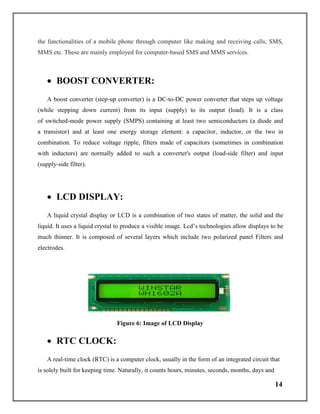
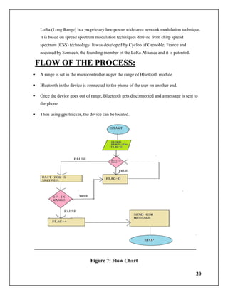
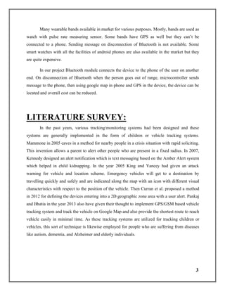
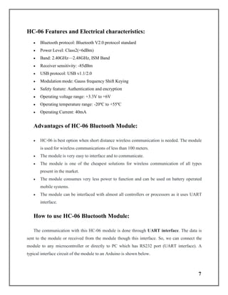
Figure 2: Image of HC 06 BLUETOOTH MODULE
Pin configuration:
HC-06 module has six pins as shown in the pinout. In them we only need to use four for
successfully interfacing the module. Some breakout boards will only leave four output pins only
because of this reason.
Pin Number Name of the
Pin
Function
1 Key The pin state determines whether the module
works in AT command mode or normal mode
[High = AT commands receiving mode
(Commands response mode), Low or NC =
Bluetooth module normally working].
2 Vcc +5V Positive supply needs to be given to this pin
for powering the module
3 GND Connect to ground
4 TXD Serial data is transmitted by module through this
pin (at 9600bps by default), 3.3V logic
5 RXD Serial data is received by module through this
pin (at 9600bps by default),3.3V logic
6 State The pin is connected to the LED on the board to
represent the state of the module
13. 7
HC-06 Features and Electrical characteristics:
Bluetooth protocol: Bluetooth V2.0 protocol standard
Power Level: Class2(+6dBm)
Band: 2.40GHz—2.48GHz, ISM Band
Receiver sensitivity: -85dBm
USB protocol: USB v1.1/2.0
Modulation mode: Gauss frequency Shift Keying
Safety feature: Authentication and encryption
Operating voltage range: +3.3V to +6V
Operating temperature range: -20ºC to +55ºC
Operating Current: 40mA
Advantages of HC-06 Bluetooth Module:
HC-06 is best option when short distance wireless communication is needed. The module
is used for wireless communications of less than 100 meters.
The module is very easy to interface and to communicate.
The module is one of the cheapest solutions for wireless communication of all types
present in the market.
The module consumes very less power to function and can be used on battery operated
mobile systems.
The module can be interfaced with almost all controllers or processors as it uses UART
interface.
How to use HC-06 Bluetooth Module:
The communication with this HC-06 module is done through UART interface. The data is
sent to the module or received from the module though this interface. So, we can connect the
module to any microcontroller or directly to PC which has RS232 port (UART interface). A
typical interface circuit of the module to an Arduino is shown below.
14. 8
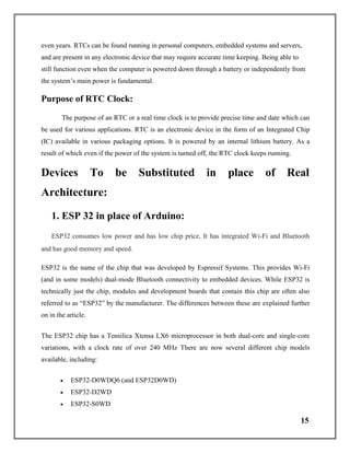
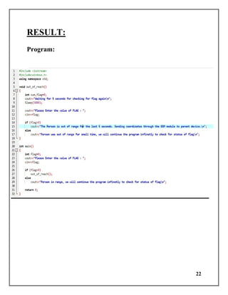
Figure 3: Diagram of typical interface circuit of the Bluetooth module to an Arduino
Here the module is connected to +5V standard regulated power supply and UART
interface is established as shown in figure. We need to do is connect RXD of Arduino to TXD of
module and TXD of Arduino is connected to RXD of module through a resistor voltage divider.
This voltage divider is provided for converting 5V logic signal sent by Arduino to +3.3V logic
signals which are suitable for the module. The ground of Arduino and module must be connected
for voltage reference in case separate power sources are used.
After connecting the module, we have to write the program in Arduino IDE to receive and
send data to the module. For successful wireless communication we need to remember few
things:
In programming we need to set default baud rate of UART serial communication to 9600.
The value is default setting of module and can be change in program.
The module is a slave and so we need a master to establish a successful wireless interface.
For that we need another [Arduino + module (with master feature)] setup or we can use a
smart phone as a master and search for HC-06 slave.
The master searches for slave and connects to it after authenticated with password. The
HC-06 module has default password ‘1234’ which can be changed.
15. 9
In program we can receive data master sends (After authentication) and perform tasks
based on it.
Also, we can download libraries for module through the websites and use them to make
communication easy. We need to do is download these libraries and call them in
programs. Once the header file is included, we can use simple commands in the program
to tell the Arduino to send or receive data. The module sends this data to master through
wireless Bluetooth. If the module receives any data from master, it will transmit it to
Arduino through UART serial communication.
GPS MODULE:
Global Positioning System, also known as GPS, is a system of satellites designed to help
navigate on the Earth, in the air, and on water. GPS receivers. People can carry them to
detect where they are and plan where and how to go to the next place. A GPS receiver shows
where it is. It may also show how fast it is moving, which direction it is going, how high it is,
and maybe how fast it is going up or down. Many GPS receivers have information about places.
GPSs for automobiles have travel data like road maps, hotels, restaurants, and service stations.
GPSs for boats contain nautical charts of harbour’s, marinas, shallow water, rocks,
and waterways. Other GPS receivers are made for air navigation, hiking and
backpacking, bicycling, or many other activities. The majority are in smartphones.
Working Principle of GPS Module:
The GPS consists of three segments:
1. The space segment: the GPS satellites
2. The control system, operated by the U.S. military,
3. The user segment, which includes both military and civilian users and their GPS
equipment.
16. 10
Space Segment:
The space segment is the number of satellites in the constellation. It comprises of 29
satellites circling the earth every 12 hours at 12,000 miles in altitude. The function of the space
segment is utilized to route/navigation signals and to store and retransmit the route/navigation
message sent by the control segment. These transmissions are controlled by highly stable atomic
clocks on the satellites. The GPS Space Segment is formed by a satellite constellation with
enough satellites to ensure that the users will have, at least, 4 simultaneous satellites in view
from any point at the Earth’s surface at any time.
Figure 4: Image of Space segment
17. 11
Control Segment:
The control segment comprises of a master control station and five monitor stations
outfitted with atomic clocks that are spread around the globe. The five monitor stations monitor
the GPS satellite signals and then send that qualified information to the master control station
where abnormalities are revised and sent back to the GPS satellites through ground antennas.
The control segment also referred to as a monitor station.
Figure 5: Image of Control segment
User Segment:
The user segment comprises of the GPS receiver, which receives the signals from the
GPS satellites and determines how far away it is from each satellite. Mainly this segment is used
for the U.S military, missile guidance systems, civilian applications for GPS in almost every
field. Most of the civilian use this from survey to transportation to natural resources and from
there to agriculture purpose and mapping too.
How GPS Determines a Position:
18. 12
The working/operation of the Global positioning system is based on the ‘trilateration’
mathematical principle. The position is determined from the distance measurements to satellites.
From the figure, the four satellites are used to determine the position of the receiver on the earth.
The target location is confirmed by the 4th
satellite. And three satellites are used to trace the
location place. A fourth satellite is used to confirm the target location of each of those space
vehicles. The global positioning system consists of satellite, control station and monitor station
and receiver. The GPS receiver takes the information from the satellite and uses the method of
triangulation to determine a user’s exact position.
Advantages of GPS:
1. GPS satellite-based navigation system is an important tool for military, civil and
commercial users.
2. Vehicle tracking systems GPS-based navigation systems can provide us with turn by turn
directions.
3. Very high speed.
GSM MODULE:
GSM: GSM (Global System for Mobile Communications), is a standard developed by the
European Telecommunications Standards Institute (ETSI).
GPRS: General Packet Radio Service (GPRS) is a packet oriented mobile data service on
the 2G and 3G cellular communication system’s global system for mobile communications
(GSM). GPRS was originally standardised by European Telecommunications Standards
Institute (ETSI) in response to the earlier CDPD and i-mode packet-switched cellular
technologies. It was created to describe the protocols for second-generation (2G) digital
cellular networks used by mobile phones and is now the default global standard for mobile
communications.
19. 13
GSM Module: A GSM module is a chip or circuit that will be used to establish
communication between a mobile device or a computing machine and a GSM or GPRS
system. The modem (modulator-demodulator) is a critical part here. These modules consist
of a GSM module or GPRS modem powered by a power supply circuit and communication
interfaces (like RS-232, USB 2.0, and others) for computer. A GSM modem can be a
dedicated modem device with a serial, USB or Bluetooth connection, or it can be a mobile
phone that provides GSM modem capabilities.
Modems: Wireless modems generate, transmit or decode data from a cellular network, in
order to establish communication. A GSM/GPRS modem is a class of wireless
modem, designed for communication over the GSM and GPRS network. It requires a SIM
(Subscriber Identity Module) card just like mobile phones to activate communication with
the network. Also, they have IMEI (International Mobile Equipment Identity) number similar
to mobile phones for their identification.
1. The MODEM needs AT commands, for interacting with processor or controller,
which are communicated through serial communication.
2. These commands are sent by the controller/processor.
3. The MODEM sends back a result after it receives a command.
4. Different AT commands supported by the MODEM can be sent by the
processor/controller/computer to interact with the GSM and GPRS cellular network.
Applications of GSM module or GPRS module:
They can feature all the functionalities of a mobile phone through computer like making and
receiving calls, SMS, MMS etc. These are mainly employed for computer-based SMS and MMS
services. The GSM/GPRS module demonstrates the use of AT commands. They can feature all
20. 14
the functionalities of a mobile phone through computer like making and receiving calls, SMS,
MMS etc. These are mainly employed for computer-based SMS and MMS services.
BOOST CONVERTER:
A boost converter (step-up converter) is a DC-to-DC power converter that steps up voltage
(while stepping down current) from its input (supply) to its output (load). It is a class
of switched-mode power supply (SMPS) containing at least two semiconductors (a diode and
a transistor) and at least one energy storage element: a capacitor, inductor, or the two in
combination. To reduce voltage ripple, filters made of capacitors (sometimes in combination
with inductors) are normally added to such a converter's output (load-side filter) and input
(supply-side filter).
LCD DISPLAY:
A liquid crystal display or LCD is a combination of two states of matter, the solid and the
liquid. It uses a liquid crystal to produce a visible image. Lcd’s technologies allow displays to be
much thinner. It is composed of several layers which include two polarized panel Filters and
electrodes.
Figure 6: Image of LCD Display
RTC CLOCK:
A real-time clock (RTC) is a computer clock, usually in the form of an integrated circuit that
is solely built for keeping time. Naturally, it counts hours, minutes, seconds, months, days and
21. 15
even years. RTCs can be found running in personal computers, embedded systems and servers,
and are present in any electronic device that may require accurate time keeping. Being able to
still function even when the computer is powered down through a battery or independently from
the system’s main power is fundamental.
Purpose of RTC Clock:
The purpose of an RTC or a real time clock is to provide precise time and date which can
be used for various applications. RTC is an electronic device in the form of an Integrated Chip
(IC) available in various packaging options. It is powered by an internal lithium battery. As a
result of which even if the power of the system is turned off, the RTC clock keeps running.
Devices To be Substituted in place of Real
Architecture:
1. ESP 32 in place of Arduino:
ESP32 consumes low power and has low chip price. It has integrated Wi-Fi and Bluetooth
and has good memory and speed.
ESP32 is the name of the chip that was developed by Espressif Systems. This provides Wi-Fi
(and in some models) dual-mode Bluetooth connectivity to embedded devices. While ESP32 is
technically just the chip, modules and development boards that contain this chip are often also
referred to as “ESP32” by the manufacturer. The differences between these are explained further
on in the article.
The ESP32 chip has a Tensilica Xtensa LX6 microprocessor in both dual-core and single-core
variations, with a clock rate of over 240 MHz There are now several different chip models
available, including:
ESP32-D0WDQ6 (and ESP32D0WD)
ESP32-D2WD
ESP32-S0WD
22. 16
And the system in package (SiP) – ESP32-PICO-D4
Models are available with combined Wi-Fi and Bluetooth connectivity, or just Wi-Fi
connectivity. The ESP32 is most commonly engineered for mobile devices, wearable tech, and
IoT applications – such as Nabto. Moreover, with Mongoose OS introducing an ESP32 IoT
Starter Kit, the ESP32 has gained a reputation as the ultimate chip or module for hobbyists and
IoT developers.
While this reputation is not unmerited, the low-cost device can also be used in a number of
different production systems, and its capabilities and resources have grown impressively over the
past four years.
ESP32 Features and Specifications: Here’s a high-level summary of the features
and specifications of the ESP32:
Sl.no ESP-32 Description
1 Core 2
2 Arquitecture 32 bits
3 Clock Tensilica Xtensa LX106 160-240MHz
4 Wi-Fi IEEE802.11 b/g/n
5 Bluetooth Yes-classic & BLE
6 Ram 520KB
7 Flash Extern QPSI- 16MB
8 GPIO 22
9 DAC 2
10 ADC 18
11 Interfaces SPI-12C-UART-12S-CAN
23. 17
Processors – As previously mentioned, the ESP32 uses a Tensilica Xtensa 32-bit
LX6 microprocessor. This uses 1 or 2 cores (all chips in the series are dual-core,
except the ESP32-S0WD). The clock frequency reaches up to 240MHz and it
performs up to 600 DMIPS (Dhrystone Million Instructions Per Second). Moreover,
its low power consumption allows for ADC conversions, computation, and level
thresholds, all while in deep sleep mode.
Wireless connectivity – The ESP32 enables connectivity to integrated Wi-Fi
through the 802.11 b/g/n/e/i/. Moreover, dual-mode Bluetooth is made possible with
the v4.2 BR/EDR and features Bluetooth Low Energy (BLE).
Memory – Internal memory for the ESP32 is as follows – ROM: 448 KiB (for
booting/core functions), SRAM: 520 KiB (for data/instructions), RTC fast SRAM: 8
KiB (for data storage/main CPU during boot from sleep mode), RTC slow SRAM: 8
KiB (for co-processor access during sleep mode), and eFuse: 1 KiBit (256 bits used
for the system (MAC address and chip configuration) and 768 bits reserved for
customer applications). Moreover, two of the ESP32 chips – ESP32-D2WD and
ESP32-PICO-D4 – have internally connected flash. The others are as follows: 0 MiB
(ESP32-D0WDQ6, ESP32-D0WD, and ESP32-S0WD chips), 2 MiB (ESP32-D2WD
chip), and 4 MiB (ESP32-PICO-D4 SiP module).
External Flash and SRAM – ESP32 supports up to four 16 MiB external
QSPI flashes and SRAMs with hardware encryption based on AES to protect
developers’ programs and data. It accesses the external QSPI flash and SRAM
through high-speed caches.
Security – IEEE 802.11 standard security features are all supported, including
WFA, WPA/WPA2 and WAPI. Moreover, ESP32 has a secure boot and flash
encryption.
24. 18
ESP32 Functions:
ESP32 has many applications when it comes to the Internet of Things (IoT). Here are just some
of the IoT functions the chip is used for:
Networking: The module’s Wi-Fi Antenna and dual-core enables embedded devices
to connect to routers and transmit data.
Data Processing: Includes processing basic inputs from analog and digital sensors to
far more complex calculations with an RTOS or Non-OS SDK.
P2P Connectivity: Creates direct communication between different ESPs and other
devices using IoT P2P connectivity.
Web Server: Access pages written in HTML or development languages.
ESP32 Applications
The ESP32 modules are commonly found in the following IoT devices:
Smart industrial devices, including Programmable Logic Controllers (PLCs)
Smart medical devices, including wearable health monitors
Smart energy devices, including HVAC and thermostats
Smart security devices, including surveillance cameras and smart locks
Chip versus Modules versus Development Boards
The ESP32 is just the name of the chip. Device manufacturers and developers have three
different choices in terms of which format they buy this in, and the decision of which one to go
with will depend on their individual circumstances:
ESP32 Chip: This is the bare-bones chip that is manufactured by Espressif. It
comes unshielded and can’t be attached to a module or board without soldering.
Therefore, most device manufacturers do not purchase just the chip, as this will add an
additional layer of complexity to the production process.
25. 19
ESP32 Modules: These are surface mountable modules that contain the chip.
The benefit of purchasing a module is that these can be easily mounted onto an MCU
in the production process. The chip is also usually shielded and pre-approved by the
FCC, which means device manufacturers do not need to worry about adding
additional steps to the production process to achieve FCC compliance with regard to
Wi-Fi shielding.
ESP32 Development Boards: These are IoT MCU development boards
that have the modules containing the ESP32 chip preinstalled. They are used by
hobbyists, device manufacturers and developers to test and prototype IoT devices
before entering mass production. There is a wide variety of makes and models of
ESP32 development boards, produced by different manufacturers. Here are some
important specs to consider when choosing a suitable IoT ESP32 development board:
GPIO pins
ADC pins
Wi-Fi antennas
LEDs
Shielding
Flash Memory
Many international markets require shielded Wi-Fi devices, as Wi-Fi produces a lot of Radio
Frequency Interference (RFI), and shielding minimizes this interference. This should, therefore,
be a key consideration for all developers and embedded device manufacturers.
2. Lora Module in place of Bluetooth Module:
The range covered using Bluetooth Module is small so we can use Lora Module to
overcome this problem.
LoRa stands for Long Range Radio and is mainly targeted for M2M and IoT networks.
This technology will enable public or multi-tenant networks to connect a number of
applications running on the same network.
26. 20
LoRa (Long Range) is a proprietary low-power wide-area network modulation technique.
It is based on spread spectrum modulation techniques derived from chirp spread
spectrum (CSS) technology. It was developed by Cycleo of Grenoble, France and
acquired by Semtech, the founding member of the LoRa Alliance and it is patented.
FLOW OF THE PROCESS:
• A range is set in the microcontroller as per the range of Bluetooth module.
• Bluetooth in the device is connected to the phone of the user on another end.
• Once the device goes out of range, Bluetooth gets disconnected and a message is sent to
the phone.
• Then using gps tracker, the device can be located.
Figure 7: Flow Chart
30. 24
FUTURE ASPECTS:
Future wearable equipment will pay more attention to the wearer's psychology and
emotional state. These devices will not only send information, but also regulate information.
Compact devices are more preferable and hence it can take the place of phones after some
enhancement. Moreover, the device will be made in very low cost and will be available readily
for users. The users can easily have a record of the location of their loved ones so it will be more
preferred for small kids, old citizens, people with Alzheimer and even for pets. Mothers can have
an eye on their kid while doing households.
This work is of low cost, very effective, and productive. But there is always room for
improvement. This merchandise has been designed as a prototype and requires further
developments for using it in assorted applications. This system can be further expended in
developing a Windows application which can support windows phone and the wearer device
must be small and unobtrusive in the form of compact watch and it should not label people.
SCOPE OF ENHANCEMENT:
We can use speaker and microphone in the device, further, to guide the direction to
someone who has no idea about using smart-phones, from distant. We can further use google
map API to check the live location constantly. Once, the device gets disconnected, it sends
message to the end user. We can further enhance it to send message on re-connecting. We can set
a time as well which will be used as an alarm. If someone is out of range for the duration longer
then as set by the user, the message will be sent. We can develop web or android application for
further enhancement in the use of this device. It can be further modified into health band and
smart watch as well.
31. 25
CONCLUSION:
This project primarily pertained to the development of a wireless monitoring system.
However, the concepts, techniques and design approach used for the development of our wireless
GPS system will be further modified to encompass several different benefits such as sending
messages on disconnection and reconnection, detecting live location and guiding direction.
Hence, the digital hand band with GPS System is a stepping stone for the development of a
Multi-parameter Wireless Band.
REFERENCES:
1. C. Yamagata, J. F. Coppola, M. Kowtko, and S. Joyce, “Mobile app development and
usability research to help dementia and Alzheimer patients,” in Proceedings of the 9th
Annual Conference on Long Island Systems, Applications and Technology (LISAT '13),
pp. 1–6, Farmingdale, NY, USA, May 2013.
2. M. Randolph-Gips, “Autism: a systems biology disease,” in Proceedings of the 1st IEEE
International Conference on Healthcare Informatics, Imaging and Systems Biology
(HISB '11), pp. 359–366, San Jose, Calif, USA, July 2011.
3. R. Mammone, “Child locator apparatus and method,” U.S. Patent Application 10/689,216,
2003.
4. P. J. Kennedy, “Mobile phone Amber alert notification system and method,” U.S. Patent
No. 7,228,121, 2007.
5. B. King and D. A. Yancey, “GPS-based vehicle warning and location system and
method,” U.S. Patent No. 6,895,332, May 2005.
6. D. Curran, J. Demmel, and R. A. Fanshier, “Geo-fence with minimal false alarms,” U.S.
Patent no. 8,125,332, February 2012.
32. 26
7. V. Pankaj and J. S. Bhatia, “Design and development of GPS-GSM based tracking
system with Google map-based monitoring,” International Journal of Computer Science,
Engineering and Applications, vol. 3, no. 3, 2013.
8. P. Wang, Z. Zhao, C. Xu, Z. Wu, and Y. Luo, “Design and implementation of the Low-
Power Tracking System based on GPS-GPRS Module,” in Proceedings of the 5th IEEE
Conference on Industrial Electronics and Applications (ICIEA '10), pp. 207–210, June
2010.
9. M. Kunal, S. Mandeep, and J. Neelu, “Real time vehicle tracking system using GSM and
GPS technology—an anti-theft tracking System,” International Journal of Electronics
and Computer Science Engineering, vol. 1, no. 3, 2012.
10. M. A. Al-Khedher, “Hybrid GPS-GSM localization of automobile tracking
system,” International Journal of Computer Science and Information Technology, vol. 3,
no. 6, pp. 75–85, 2011.
11. P. B. Fleischer, A. Y. Nelson, R. A. Sowah, and A. Bremang, “Design and development
of GPS/GSM based vehicle tracking and alert system for commercial inter-city buses,”
in Proceedings of the IEEE 4th International Conference on Adaptive Science and
Technology (ICAST '12), pp. 1–6, IEEE, October 2012.
12. J.-H. Liu, J. Chen, Y.-L. Wu, and P.-L. Wang, “AASMP-Android Application Server for
Mobile Platforms,” in Proceedings of the IEEE 16th International Conference on
Computational Science and Engineering (CSE '13), pp. 643–650, 2013.
13. J. Saranya and J. Selvakumar, “Implementation of children tracking system on android
mobile terminals,” in Proceedings of the International Conference on Communications
and Signal Processing (ICCSP '13), pp. 961–965, April 2013.
14. N. Chadil, A. Russameesawang, and P. Keeratiwintakorn, “Real-time tracking
management system using GPS, GPRS and Google Earth,” in Proceedings of the 5th
International Conference on Electrical Engineering/Electronics, Computer,
Telecommunications and Information Technology (ECTI-CON '08), vol. 1, pp. 393–396,
Krabi, Thailand, May 2008.
33. 27
15. Y. A. N. G. Mei, “Application design and implementation of GPS-GPRS location system
vehicle terminals,” Telecommunication Engineering, vol. 3, article 024, 2004.
16. L. Rui, Z. Minjian, L. Wenhu, and H. Tao, “Designed and implementation of the
positioning and tracking system based on GSM SMS module,” Journal of Electronic
Measurement and Instrument, no. z1, pp. 283–286, 2008.