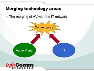
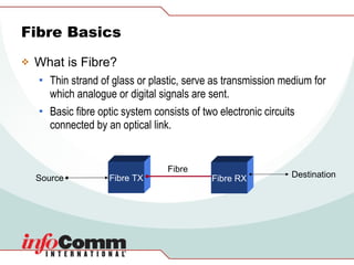
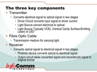
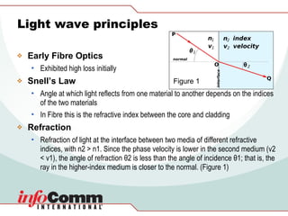
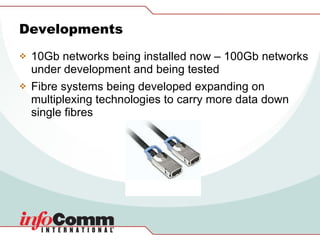
Fibre Optics and its Importance for AV Presented By:  Frank Sheehan 10951_ICIA_Template_STD_Final.ppt ICIA Confidentiality Message, Da
Introduction Technology Areas using Fibre AV/IT Convergence Fibre Basics Types of Extenders Switching Digital Impact Trends & future
Technology Areas Telecommunication ICT Network Computing (HPC – High Performance Computing) Fibre Channel – storage Other high bandwidth fibre technologies e.g Infiniband etc Voice over IP AV
Merging technology areas The merging of AV with the IT network Audio Visual IT Convergence
Fibre Basics What is Fibre? Thin strand of glass or plastic, serve as transmission medium for which analogue or digital signals are sent. Basic fibre optic system consists of two electronic circuits connected by an optical link.  Fibre TX Fibre RX Source Destination Fibre
The three key components Transmitter Converts electrical signal to optical signal in two stages Driver Circuit converts input signal to driver current Light Source convert electrical to optical Light Source Typically VCEL (Vertical Cavity Surface-Emitting Laser) or LED  Fibre Optic Cable Transmission medium for carrying light. Receiver Converts optical signal to electrical signal in two stages Photonic device converts optical to electrical signal Output circuit takes converted signal and reconstructs signal to original format
Light wave principles Early Fibre Optics  Exhibited high loss initially Snell’s Law Angle at which light reflects from one material to another depends on the indices of the two materials In Fibre this is the refractive index between the core and cladding Refraction   Refraction of light at the interface between two media of different refractive indices, with n2 > n1. Since the phase velocity is lower in the second medium (v2 < v1), the angle of refraction θ2 is less than the angle of incidence θ1; that is, the ray in the higher-index medium is closer to the normal. (Figure 1) Figure 1
Transmission Windows Wavelength a key factor within fibre As specified by the International Telecommunication Union (ITU)
Fibre construction Glass Glass Core & Glass Cladding Different Elements added to glass to increase or decrease refractive index such as germanium & phosphorus to increase & Boron or Fluorine to decrease Plastic–Clad Silica (PCS) Glass Core & Plastic Cladding Plastic (POF) Plastic Core & Plastic Cladding
Fibre construction (cont) Core Glass or Plastic or PCS  Typically 8-200 microns (µm) Ø Cladding Provides difference in refractive index allowing internal reflection through core Coating Typically layers of polymer Strengthening Fibres Typically Kevlar Cable Jacket PVC (Non-Plenum) Fluoride Co-Polymer (Plenum)
Light Propagation Total Internal Reflection (TIR) Intermodal Dispersion  (sometimes known as Differential Mode Delay, DMD) Graded index Fibres
Intermodal Dispersion Farther light goes from centre of fibre, the faster its speed Speed difference compensates for longer paths Equalizing of transit times reduces modal dispersion Modal Dispersion may reduced considerably, but never completely eliminated
Graded Index Fibre
Fibre Modes Multimode Typically 50µm or 62.5µm Single-mode Typically 8µm or 9µm Core & Cladding Diameters  of four commonly used fibres
Fibre Types (Premises Cables) Simplex Single Jacketed Cable Duplex or Zip Cord Dual individual jacketed Cables Distribution Small in size Requires termination within Patch Panel Breakout Less labour intensive for termination
Fibre Rating NEC – National Electrical Code – for all Premises cables Low Smoke Density OFN-LS Plenum rated for use in air handling plenums OFNP or OFCP Riser Rated for vertical runs OFNR or OFCR General Purpose OFNG or OFCG Optical Fibre Conductive OFC Optical Fibre Non-conductive OFN Description NEC Rating
Fibre Connectors LC SC ST
Optical Budget What is Optical Budget? The difference between power launched optics at source and received power at other end What is Optical Loss Budget? The minimum amount of optical power needed for the receiver to correctly recover signal
Optical Fibre Loss Table showing typical Optical Fibre Loss Other Sources of loss Patch Panels – 0.1dB to greater than 1dB
Patch Panels  SC Patch Panel Example
Fibre Bandwidth Intermodal Dispersion Limits distance capacity of multimode  fibre reducing bandwidth Chromatic Dispersion Due to light of different colours (wavelengths) travelling at different  speeds in the core of the fibre Polarized Mode Dispersion (PMD) A property also called birefringence within single-mode fibre.
CWDM Coarse Wave Division Multiplexing Up to 18 Wavelengths evenly spaced 1270nm-1610nm @ 20nm increments Provided in Multimode and Single-mode systems
DWDM Dense Wave-Division Multiplexing Only 0.8nm channel spacing Single mode only
Video Extenders
Example of DVI interconnect
HD-SDI Interconnect
Rack mounted Systems
Racked Cage Systems
Switching Optical-Optical-Optical (OOO) Utilizing MEM’s technology ( Micro Electro Mechanical)   Optical-Electrical-Optical (OEO)
Optical System Example
Digital Impact Transition from the analogue world to the digital world on the copper infrastructure Analogue Digital Last 10 years Signal Last 10 years Distance
Video  HD-SDI Dual Link – 10 bit colour  3G (2.97Gbit/s) DVI-D Single Link Dual Link – 10 bit colour HDMI Display Port 10.8Gbit/s data rate
Dual Link DVI-D Example Data Rate Example 70fps × 30bpp (RGB) × 2560 × 1600 = 7.4 Gbit/s 60fps × 36bpp (YCbCr 4:4:4) × 1920× 1080 = 4.5 Gbit/s
Audio TOSLINK (TOShiba-LINK) ADAT (Lightpipe)[ Alesis Digital Audio Tape] SPDIF [ Sony Philips Digital InterFace ] AES/EBU (AES3) [Audio Engineering Society & European Broadcasting Union] MADI [Multichannel Audio Digital Interface] Networked Audio EtherSound CobraNet
Data Interconnects USB 1.0 = 12Mbit/s 2.0 =  480Mbit/s 3.0 (Future Version) = 4.8GBit/s (Utilizing  parallel optical cable) Firewire (IEEE 1394) 1394 & 1394a = 400Mbits/s 1394b = 800Mbit/s S1600 = 1.6Gbit/s S3200 = 3.2Gbit/s Future iterations = 6.4Gbit/s or >
Trends  Increased loading upon infrastructure – Why? Future requirements? Bandwidth VoIP Audio Data IPTV VC Video
Developments 10Gb networks being installed now – 100Gb networks under development and being tested Fibre systems being developed expanding on multiplexing technologies to carry more data down single fibres
Future? 3D Immersive Telepresence requiring large bandwidth
David Thomson  of Avolution  www.avolution.co.uk   Ian Patrick  of Network Cabling Help  www.datacottage.com   Jesus Izquierdo  of Emcore  www.opticomm.com   Jim Jachetta  of MultiDyne  www.multidyne.com   Peter Henderson & Dan Karz  of Think Logical  www.thinklogical.com   Credits Thanks go out to the following for permissions of image use and information kindly donated by the following :
Thank you for your attention
Contact Details Frank Sheehan Director of Technology – Visual  Acuity  Limited [email_address] Cell: +44(0)7900 904928 Tel: +44(0)8700 775040 Skype: franksheehan

Fibre Optics Seminar Ise09

  • 1.
    Fibre Optics andits Importance for AV Presented By: Frank Sheehan 10951_ICIA_Template_STD_Final.ppt ICIA Confidentiality Message, Da
  • 2.
    Introduction Technology Areasusing Fibre AV/IT Convergence Fibre Basics Types of Extenders Switching Digital Impact Trends & future
  • 3.
    Technology Areas TelecommunicationICT Network Computing (HPC – High Performance Computing) Fibre Channel – storage Other high bandwidth fibre technologies e.g Infiniband etc Voice over IP AV
  • 4.
    Merging technology areasThe merging of AV with the IT network Audio Visual IT Convergence
  • 5.
    Fibre Basics Whatis Fibre? Thin strand of glass or plastic, serve as transmission medium for which analogue or digital signals are sent. Basic fibre optic system consists of two electronic circuits connected by an optical link. Fibre TX Fibre RX Source Destination Fibre
  • 6.
    The three keycomponents Transmitter Converts electrical signal to optical signal in two stages Driver Circuit converts input signal to driver current Light Source convert electrical to optical Light Source Typically VCEL (Vertical Cavity Surface-Emitting Laser) or LED Fibre Optic Cable Transmission medium for carrying light. Receiver Converts optical signal to electrical signal in two stages Photonic device converts optical to electrical signal Output circuit takes converted signal and reconstructs signal to original format
  • 7.
    Light wave principlesEarly Fibre Optics Exhibited high loss initially Snell’s Law Angle at which light reflects from one material to another depends on the indices of the two materials In Fibre this is the refractive index between the core and cladding Refraction Refraction of light at the interface between two media of different refractive indices, with n2 > n1. Since the phase velocity is lower in the second medium (v2 < v1), the angle of refraction θ2 is less than the angle of incidence θ1; that is, the ray in the higher-index medium is closer to the normal. (Figure 1) Figure 1
  • 8.
    Transmission Windows Wavelengtha key factor within fibre As specified by the International Telecommunication Union (ITU)
  • 9.
    Fibre construction GlassGlass Core & Glass Cladding Different Elements added to glass to increase or decrease refractive index such as germanium & phosphorus to increase & Boron or Fluorine to decrease Plastic–Clad Silica (PCS) Glass Core & Plastic Cladding Plastic (POF) Plastic Core & Plastic Cladding
  • 10.
    Fibre construction (cont)Core Glass or Plastic or PCS Typically 8-200 microns (µm) Ø Cladding Provides difference in refractive index allowing internal reflection through core Coating Typically layers of polymer Strengthening Fibres Typically Kevlar Cable Jacket PVC (Non-Plenum) Fluoride Co-Polymer (Plenum)
  • 11.
    Light Propagation TotalInternal Reflection (TIR) Intermodal Dispersion (sometimes known as Differential Mode Delay, DMD) Graded index Fibres
  • 12.
    Intermodal Dispersion Fartherlight goes from centre of fibre, the faster its speed Speed difference compensates for longer paths Equalizing of transit times reduces modal dispersion Modal Dispersion may reduced considerably, but never completely eliminated
  • 13.
  • 14.
    Fibre Modes MultimodeTypically 50µm or 62.5µm Single-mode Typically 8µm or 9µm Core & Cladding Diameters of four commonly used fibres
  • 15.
    Fibre Types (PremisesCables) Simplex Single Jacketed Cable Duplex or Zip Cord Dual individual jacketed Cables Distribution Small in size Requires termination within Patch Panel Breakout Less labour intensive for termination
  • 16.
    Fibre Rating NEC– National Electrical Code – for all Premises cables Low Smoke Density OFN-LS Plenum rated for use in air handling plenums OFNP or OFCP Riser Rated for vertical runs OFNR or OFCR General Purpose OFNG or OFCG Optical Fibre Conductive OFC Optical Fibre Non-conductive OFN Description NEC Rating
  • 17.
  • 18.
    Optical Budget Whatis Optical Budget? The difference between power launched optics at source and received power at other end What is Optical Loss Budget? The minimum amount of optical power needed for the receiver to correctly recover signal
  • 19.
    Optical Fibre LossTable showing typical Optical Fibre Loss Other Sources of loss Patch Panels – 0.1dB to greater than 1dB
  • 20.
    Patch Panels SC Patch Panel Example
  • 21.
    Fibre Bandwidth IntermodalDispersion Limits distance capacity of multimode fibre reducing bandwidth Chromatic Dispersion Due to light of different colours (wavelengths) travelling at different speeds in the core of the fibre Polarized Mode Dispersion (PMD) A property also called birefringence within single-mode fibre.
  • 22.
    CWDM Coarse WaveDivision Multiplexing Up to 18 Wavelengths evenly spaced 1270nm-1610nm @ 20nm increments Provided in Multimode and Single-mode systems
  • 23.
    DWDM Dense Wave-DivisionMultiplexing Only 0.8nm channel spacing Single mode only
  • 24.
  • 25.
    Example of DVIinterconnect
  • 26.
  • 27.
  • 28.
  • 29.
    Switching Optical-Optical-Optical (OOO)Utilizing MEM’s technology ( Micro Electro Mechanical) Optical-Electrical-Optical (OEO)
  • 30.
  • 31.
    Digital Impact Transitionfrom the analogue world to the digital world on the copper infrastructure Analogue Digital Last 10 years Signal Last 10 years Distance
  • 32.
    Video HD-SDIDual Link – 10 bit colour 3G (2.97Gbit/s) DVI-D Single Link Dual Link – 10 bit colour HDMI Display Port 10.8Gbit/s data rate
  • 33.
    Dual Link DVI-DExample Data Rate Example 70fps × 30bpp (RGB) × 2560 × 1600 = 7.4 Gbit/s 60fps × 36bpp (YCbCr 4:4:4) × 1920× 1080 = 4.5 Gbit/s
  • 34.
    Audio TOSLINK (TOShiba-LINK)ADAT (Lightpipe)[ Alesis Digital Audio Tape] SPDIF [ Sony Philips Digital InterFace ] AES/EBU (AES3) [Audio Engineering Society & European Broadcasting Union] MADI [Multichannel Audio Digital Interface] Networked Audio EtherSound CobraNet
  • 35.
    Data Interconnects USB1.0 = 12Mbit/s 2.0 = 480Mbit/s 3.0 (Future Version) = 4.8GBit/s (Utilizing parallel optical cable) Firewire (IEEE 1394) 1394 & 1394a = 400Mbits/s 1394b = 800Mbit/s S1600 = 1.6Gbit/s S3200 = 3.2Gbit/s Future iterations = 6.4Gbit/s or >
  • 36.
    Trends Increasedloading upon infrastructure – Why? Future requirements? Bandwidth VoIP Audio Data IPTV VC Video
  • 37.
    Developments 10Gb networksbeing installed now – 100Gb networks under development and being tested Fibre systems being developed expanding on multiplexing technologies to carry more data down single fibres
  • 38.
    Future? 3D ImmersiveTelepresence requiring large bandwidth
  • 39.
    David Thomson of Avolution www.avolution.co.uk Ian Patrick of Network Cabling Help www.datacottage.com Jesus Izquierdo of Emcore www.opticomm.com Jim Jachetta of MultiDyne www.multidyne.com Peter Henderson & Dan Karz of Think Logical www.thinklogical.com Credits Thanks go out to the following for permissions of image use and information kindly donated by the following :
  • 40.
    Thank you foryour attention
  • 41.
    Contact Details FrankSheehan Director of Technology – Visual Acuity Limited [email_address] Cell: +44(0)7900 904928 Tel: +44(0)8700 775040 Skype: franksheehan