Download as PDF, PPTX
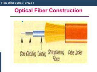
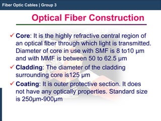
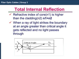
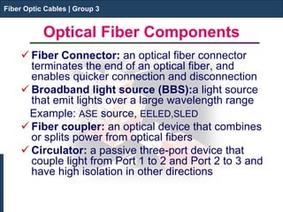
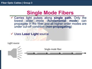
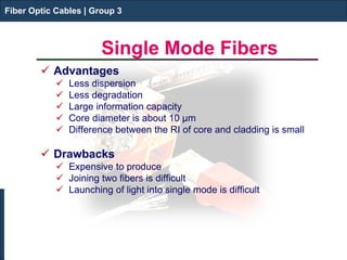
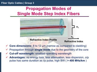
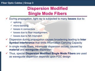
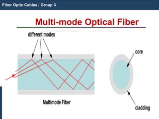
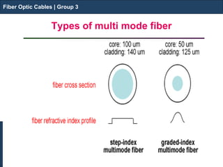


This document discusses fiber optic cables and their components. It begins by classifying optical fibers into single-mode fibers, which carry light along a single path, and multi-mode fibers, which carry multiple light paths. It then describes the core, cladding and coating layers that make up an optical fiber. Total internal reflection is discussed as the mechanism that keeps light confined in the fiber. Common fiber optic components like connectors, couplers and circulators are also outlined.


