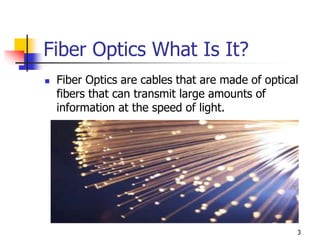
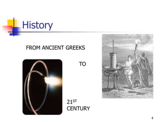
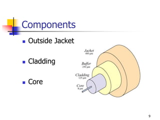
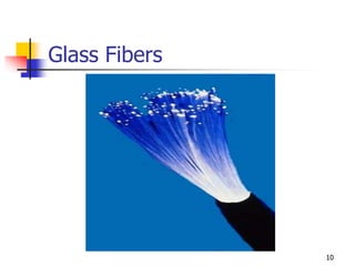
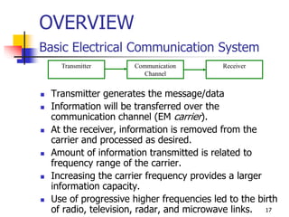
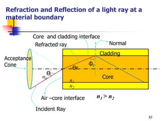
OPTICAL FIBER
COMMUNICATION -1
Dr. Pallavi Khare
Associate Professor
1
Outline
 Fiber Optics What is it?
 History
 Fiber Optic cables : Types
 Fiber Materials & Fabrication
 Optical Fiber structures & Waveguiding
2
Fiber Optics What Is It?
 Fiber Optics are cables that are made of optical
fibers that can transmit large amounts of
information at the speed of light.
3
4
FROM ANCIENT GREEKS
TO
21ST
CENTURY
History
History
 1961-“Industry researchers Elias Snitzer and
Will Hicks demonstrate a laser beam directed
through a thin glass fiber. The fiber’s core is
small enough that the light follows a single
path, but most scientists still consider fibers
unsuitable for communications because of the
high loss of light across long distances.”
 1970- Researchers find a way to super purify
glass fibers.
 1980- At&t installs first set of fiber optic
cables in major cities.
5
History
 1988- First transatlantic cable
 1996- First transpacific cable
 1997- First Fiber Optic Link Around the
Globe (FLAG)
6
Present
 Telecommunications
 Internet Access
 Cable and Satellite Television
 Decorative Light Source
7
The Cable
 Fiber Optic have three major
characteristics
 Composed of fibers either glass or plastic
and sometimes both
 Are very flexible
 Have different tips
8
Components
 Outside Jacket
 Cladding
 Core
9
Glass Fibers
10
Characteristics
 Glass Core
 Glass Cladding
 Ultra Pure Ultra Transparent Glass
 Made Of Silicon Dioxide
 Low Attenuation
 Popular among industries 11
Plastic Fibers
12
Characteristics
•Core Generally Consists Of Polymethyl
Methacrylate (Acrylic Glass) (PMMA)
Coated With A Fluoropolymer
•High Attenuation
•Used Mostly In Automotives
•Affordable
•Very Durable 13
Plastic Clad-Silica
(PCS)
 Glass Fiber Core sometimes silicone
 Cladding is Plastic or silicone
 Silicone covering and insulators
 Not common
 Has Defects
14
The Future
15
The Internet
16
OVERVIEW
Basic Electrical Communication System
 Transmitter generates the message/data
 Information will be transferred over the
communication channel (EM carrier).
 At the receiver, information is removed from the
carrier and processed as desired.
 Amount of information transmitted is related to
frequency range of the carrier.
 Increasing the carrier frequency provides a larger
information capacity.
 Use of progressive higher frequencies led to the birth
of radio, television, radar, and microwave links.
Communication
Channel
ReceiverTransmitter
17
18
Communication Systems in the EM Spectrum
Why Fiber Optics ?
Theoretical information capacity of Optical
Communications are:
 1014Hz / 1GHz(BW of each MW channel)
= 1014 /109 = 105 MW channels.
 1014Hz/100MHz (each TV channel) = 1014 /100x106
= 10x106 = 10 million TV channels.
 1014 Hz/1000Hz(each voice channel) = 1011
= 100x1000x106 = Hundred thousand
million voice channels
19
Advantages of Fiber Optic Links
 Enormous potential bandwidth
Fiber Cable has nearly 4.5 time as much
capacity as the wire cable and cross sectional
area is 30 times less
Fiber cable Metal Cable
No. of fibers/wires 144 fibers 900 twisted wires
Diameter(mm) 12.7 70
Each fiber/wire
carries
672 calls 24 calls
Total Capacity 96,768 calls 21,600 calls
20
 Small size, weight and low transmission loss
 Dielectric nature and electric isolation
 Signal security
 Potential low cost
 No permanent damage due to nuclear radiation
Fiber Cable RG – 19/U
Coaxial Cable
Diameter(mm) 2.5 28.4
Weight (Kg/km) 2 1110
Loss (dB/km) 3 22.6
21
Basic Network Information Rates
 Common Analog Systems
Message
Type
Bandwidth Comments
Voice 4 kHz Single telephone channel
Music 10 kHz AM radio Broadcasting
Music 200 kHz FM radio Broadcasting
Television 6 MHz Television Broadcasting
22
Examples of Information rates for voice,
video, and data services
Type of service Data rate
Voice (single channel) 64 kb/s
Video on demand / interactive TV 1.5-6 Mb/s
Video Games 1-2 Mb/s
Remote Education 1.5-3 Mb/s
Electronic Shopping 1.5-6 Mb/s
Data transfer 1-3 Mb/s
Video Conferencing 0.384-2 Mb/s
23
Digital Transmission Hierarchy
24
Digital Multiplexing levels used in North
America, Europe and Japan
Digital
Multiplexing
level
Number of
64 kb/s
channels
Bit rate (Mb/s)
North
America
Europe Japan
0 1 0.064 0.064 0.064
1 24 1.544 1.544
2 96 6.312 6.312
3 480 34.368 32.064
672 44.376
4 1920 139.264
4032 274.176
25
Commonly used SONET and SDH
Transmission Rates
SONET – Synchronous optical network in North America.
SDH - Synchronous digital hierarchy in other parts of the world
OC- 1 – Optical carrier level 1
STS-1 – Synchronous transport signal-level 1
STM-1 – Synchronous transport module – level 1
SONET Level Electrical Level Line Rate
(Mb/s)
SDH
equivalent
OC-1 STS-1 51.84 -
OC-3 STS-3 155.52 STM-1
OC-12 STS-12 622.08 STM-4
OC-24 STS-24 1244.16 STM-8
OC-48 STS-48 2488.32 STM-16
OC-96 STS-96 4976.64 STM-32
OC-192 STS-192 9953.28 STM-64
26
Evaluation of Fiber Optics Systems
Operating Ranges of Components 27
Increase of capacity of light wave systems
over the generations
28
Evaluation of Lightwave System
1st
Generation
(1970-79)
2nd
Generation
(1980-87)
3rd
Generation
(1985-90)
4th
Generation
(1992-2000)
5th
Generation
> 2000
Laser
Source
GaAs
800 nm
InGaAsP
1300 nm
InGaAsP ,SM
1550 nm
64 WDM s
C-band
27 WDM s
Soliton Pulses
& Amplifiers
Fiber MM MM & SM SM, dispersion
shifted
Submarine
cable
Capacity 45 Mb/s MM, 100Mb/s 2.5 Gb/s 2.5 Tb/s 20 Gb/s each
channel
Repeater
Spacing
10 km 50 km 60-70 km 60-80 km > 100 km
Total
Distance
2,50,000 km
29
Major Elements of an Optical Fiber Link
30
Optical Fiber Cable Installations
31
History of Attenuation
32
SONET/SDH Optical Network
33
Fiber Applications
Voice
Telephone Trunk
Interoffice
Intercity
Transoceanic
Subscriber service
Fiber-to-the-home
Broadband service
Near power plants
Along power lines
Along Electric Railways
Field Communications
Video
Broadcast TV
Live Events
TV mini-cameras
CATV
Source-to-headend trunk lines
Distribution
Subscriber taps
Surveillance
Remote monitoring
Fiber guided missile
Fiber-to-the-home
34
Data
Computers
CPU to peripherals
CPU to CPU
Interoffice data links
Local-area networks
Fiber-to-the-home
Aircraft wiring
Ship wiring
Satellite ground stations
Sensors
Gyroscope
Hydrophone
Position
Temperature
Electric and Magnetic
Fields
35
FIBER OPTIC CABLES
36
Types of Strengthening and
Protection Needed
 Tensile strength
 Crush Resistance
 Protection from excess bending
 Abrasion protection
 Vibration Isolation
 Moisture and Chemical protection
37
Structures of Fiber Cables
 Single and Multi fiber cables
 Tightly packed and loosely held fibers
 Centrally & Externally located
strengthening members
 Dielectric & metallic strengthening
members
 Circular geometries and ribbon
geometries
38
Cable Design Examples
Designs for Heavy Duty Fiber Cables
Designs for Light Duty Fiber Cables
39
Optical Fiber Cable for Duct Installation
40
Aerial Fiber Cables
41
Telecommunications Cable
42
Loose Tube Cable
43
Submarine Optical Cable
44
Ribbon Cable
45
FIBER MATERIALS
AND
FABRACTION
46
Material Considerations
 It must be possible to make long, thin, and
flexible fibers from the material.
 The material must be transparent at a
particular wavelength to guide the light
efficiently.
 Requires physically compatible materials with
slightly different refractive indices for the core
and cladding.
 Materials that satisfy these requirements are
glasses and plastics. 47
Why Silica-Based Glass ?
 Intrinsic low loss in NIR where Sources and
detectors are available.
 Minimum in material dispersion Coincides
with low loss wavelengths.
 Intrinsic high strength.
 Excellent chemical durability and stability.
 Low thermal expansion.
 High purity Chemicals available.
 Low cost and toxicity.
48
Other Systems Under Consideration
 Flouride glasses
(ZBLAN - ZrF4, BaF2, LaF3, AlF3 , NaF for core)
(ZHBLAN - partial replacement of ZrF4 by HaF4 for Clad)
 Active glass
(Rare earth dopents- Erbium and Neodymium in silica and halide
glasses for amplification and phas retardation)
 Plastic clad silica –PCS
(Silica core, and polymer- Silicon resign clad)
 Plastics
(Polymethylmehacrylate core and a copolymer clad)
 Chalgenide glass fibers
(As 40 S58 Se2 core and As2S3 clad fibers for Optical amplifiers, switches
and fiber lasers)
49
Glass Fibers
Variation in Refractive Index with Doping
 GeO2 – SiO2 core; SiO2 cladding
 P2 O5 - SiO2 core; SiO2 cladding
 SiO2 core; B2O3 - SiO2 cladding
 GeO2 – B2O3 -SiO2 core; B2O3- SiO2 cladding
50
Fiber Fabrication
Major Preform fabrication methods
 Outside Vapor-Phase oxidation (OVPO)
 Vapor Phase Axial Deposition (VAD)
 Modified Chemical Vapor Deposition
(MCVD)
 Plasma – activated Chemical Vapor
Deposition (PCVD)
51
Preform by Outside Vapor Phase
Oxidation (OVPO)
52
Preform by Vapor Phase Axial
Deposition (VAD)
53
Preform by Modified Chemical Vapor
Deposition (MCVD)
54
Preform by Plasma Activated
Chemical Vapor Deposition (PCVD)
55
Fiber Drawing from Preform
56
Double Crucible Method for Drawing
Fibers from Molten Glass
57
Principle Types of Coating Materials
& Characteristics
 Primary-Soft, low modulus, Good adhesion to glass surface
Thermal or UV curable silicones
UV– Curable Acrylates
Thermoplastic Rubber Compounds
 Secondary–Tough, High Modulus, Surface protection
Thermal or UV Curable Silicones
UV – Curable Acrylates
 Hermetic - Amorphous Carbon, Diamond Like carbon
Metallic – Aluminum
Polyimide
58
Qualification Tests for Fibers
 Optical Tests
 Temperature – Humidity test
 Microbend Attenuation
 Bend loss
 Mechanical Tests
 Dynamic Strength
 Dynamic & Static Fatigue
 Temperature Humidity Aging
 Fluid Immersion
 Coating Strip Force
 Glass-Coating Adhesion
59
Optical Fibers
60
OPTICAL FIBER STRUCTURES
AND
WAVEGUIDING
61
Refraction and Reflection of a light ray at a
material boundary
62
фc
Ѳi
Ѳr
n0
n1
n2
Cladding
Core
Core and cladding interface
Normal
Air –core interface
Incident Ray
Refracted ray
n1 > n2
Acceptance
Cone
Acceptance Angle and Acceptance
Cone
63
0
1
2
Angle of Incidence
Angle of Refraction
- Angle of incidance of refrated ray in the core
n Refractive Index of air
n Refractive Index of Core
n Ref
i
r
Let 







0 1
0 1
ractive Index of Cladding
sin sin
sin sin(90 )
i r
i
n n
n n
 
 

 
64
1
0
1
0
largest value of occurs when =
ABC we have
(90 )
i
r
i c
r
i
Sin n
Sin n
The
from
Sin Sin Cos
n
Sin Cos
n


  
  
 


  

65
max
1
max
0
0
1 2
2
1
when = ,
But (90 )
. . and
c i
c
c
c
But
n
Sin Cos
n
n Sin n Sin
n
i e Sin
n
   
 






66
0 1
2
0 1
2
2
1 2
1
sin
sin 1
= 1
i c
i c
n n Cos
n n Sin
n
n
n
 
 

 

67
2 2
0 1 2
2 2
1 2
0
0
1 2 2
1 2
sin
sin
if fiber surrounding medium is air then n =1
Half angle of acceptance
i
i
i
n n n
n n
n
But
Sin n n


 
 


  
Representation of the Critical angle and total
internal reflection at a glass-air interface
Sin  c = n 2 / n 1 (for  2 = 900 )
68
69
Phase shifts occurring from the reflection of
wave components normal (N) and parallel (P) to
the plane of incidence
 When light is totally internally
reflected, a phase change 
occurs in the reflected wave
(when  1 < /2 -  c ). It is
given by
tan N /2 = ( n2 cos2  1–1)/n sin 1
and
tan p /2 = n ( n2 cos2 1–1)/sin 1
70
Transmission by Cylindrical fibers
Meridional rays & Skew rays
71
 Development of clad optical fibers is most significant in the technology
of fiber optics
 Fiber perturbations gives mode coupling
72
Fiber Types
Step Index fibers
73
Graded Index Fiber
74
Launching Light into an Optical Fiber
NA = n0 sin  a =  ( n 1
2 - n 2
2 )
NA = Numerical aperture
 a = Acceptance angle of the fiber 75
Modes in Optical Fibers
 Mode is a stable propagation state in an optical fiber
 If light travels along certain paths, the EM fields reinforce each other to form a field
distribution that is stable as it travels down the fiber.
 If the light tries to travel other paths, a stable wave will not propagate – thus no mode
76
Electric Field Configurations in Cylindrical Fiber
 Model Equation
(J+K) (k1
2 J+ k2
2 K)
= (/a)2 (1/u2 + 1/w2)2
 Condition for Bound Mode
n2 k = k2    k1 = n1k
 TM mode for Hz = 0 and Ez  0
 TE mode for Ez = 0 and Hz  0
77
 Each mode has a characteristic number M.
A mode M is associated with all rays traveling at an angle M
M =  ((M+1)/2Dn1) radians
where  is the wavelength, D is core diameter, n1 is the
refractive index of the core and ‘a’ is the radius.
 The number of modes that can propagate through a step index
fiber is
Mm = V2 /2 , where V = (2 a/ ) ( n1
2 - n2
2 ) ½  2.405
V is the geometric parameter of the fiber.
For example, 100 m core SI MM fiber with NA = 0.29 would
transmit 5744 modes at 850nm.
78
Lowest Order Modes
Mode-field diameter in SM Fiber
79
Polarizations of
fundamental
mode – HE11
80
81

Optical fiber communication

  • 1.
    OPTICAL FIBER COMMUNICATION -1 Dr.Pallavi Khare Associate Professor 1
  • 2.
    Outline  Fiber OpticsWhat is it?  History  Fiber Optic cables : Types  Fiber Materials & Fabrication  Optical Fiber structures & Waveguiding 2
  • 3.
    Fiber Optics WhatIs It?  Fiber Optics are cables that are made of optical fibers that can transmit large amounts of information at the speed of light. 3
  • 4.
  • 5.
    History  1961-“Industry researchersElias Snitzer and Will Hicks demonstrate a laser beam directed through a thin glass fiber. The fiber’s core is small enough that the light follows a single path, but most scientists still consider fibers unsuitable for communications because of the high loss of light across long distances.”  1970- Researchers find a way to super purify glass fibers.  1980- At&t installs first set of fiber optic cables in major cities. 5
  • 6.
    History  1988- Firsttransatlantic cable  1996- First transpacific cable  1997- First Fiber Optic Link Around the Globe (FLAG) 6
  • 7.
    Present  Telecommunications  InternetAccess  Cable and Satellite Television  Decorative Light Source 7
  • 8.
    The Cable  FiberOptic have three major characteristics  Composed of fibers either glass or plastic and sometimes both  Are very flexible  Have different tips 8
  • 9.
  • 10.
  • 11.
    Characteristics  Glass Core Glass Cladding  Ultra Pure Ultra Transparent Glass  Made Of Silicon Dioxide  Low Attenuation  Popular among industries 11
  • 12.
  • 13.
    Characteristics •Core Generally ConsistsOf Polymethyl Methacrylate (Acrylic Glass) (PMMA) Coated With A Fluoropolymer •High Attenuation •Used Mostly In Automotives •Affordable •Very Durable 13
  • 14.
    Plastic Clad-Silica (PCS)  GlassFiber Core sometimes silicone  Cladding is Plastic or silicone  Silicone covering and insulators  Not common  Has Defects 14
  • 15.
  • 16.
  • 17.
    OVERVIEW Basic Electrical CommunicationSystem  Transmitter generates the message/data  Information will be transferred over the communication channel (EM carrier).  At the receiver, information is removed from the carrier and processed as desired.  Amount of information transmitted is related to frequency range of the carrier.  Increasing the carrier frequency provides a larger information capacity.  Use of progressive higher frequencies led to the birth of radio, television, radar, and microwave links. Communication Channel ReceiverTransmitter 17
  • 18.
  • 19.
    Why Fiber Optics? Theoretical information capacity of Optical Communications are:  1014Hz / 1GHz(BW of each MW channel) = 1014 /109 = 105 MW channels.  1014Hz/100MHz (each TV channel) = 1014 /100x106 = 10x106 = 10 million TV channels.  1014 Hz/1000Hz(each voice channel) = 1011 = 100x1000x106 = Hundred thousand million voice channels 19
  • 20.
    Advantages of FiberOptic Links  Enormous potential bandwidth Fiber Cable has nearly 4.5 time as much capacity as the wire cable and cross sectional area is 30 times less Fiber cable Metal Cable No. of fibers/wires 144 fibers 900 twisted wires Diameter(mm) 12.7 70 Each fiber/wire carries 672 calls 24 calls Total Capacity 96,768 calls 21,600 calls 20
  • 21.
     Small size,weight and low transmission loss  Dielectric nature and electric isolation  Signal security  Potential low cost  No permanent damage due to nuclear radiation Fiber Cable RG – 19/U Coaxial Cable Diameter(mm) 2.5 28.4 Weight (Kg/km) 2 1110 Loss (dB/km) 3 22.6 21
  • 22.
    Basic Network InformationRates  Common Analog Systems Message Type Bandwidth Comments Voice 4 kHz Single telephone channel Music 10 kHz AM radio Broadcasting Music 200 kHz FM radio Broadcasting Television 6 MHz Television Broadcasting 22
  • 23.
    Examples of Informationrates for voice, video, and data services Type of service Data rate Voice (single channel) 64 kb/s Video on demand / interactive TV 1.5-6 Mb/s Video Games 1-2 Mb/s Remote Education 1.5-3 Mb/s Electronic Shopping 1.5-6 Mb/s Data transfer 1-3 Mb/s Video Conferencing 0.384-2 Mb/s 23
  • 24.
  • 25.
    Digital Multiplexing levelsused in North America, Europe and Japan Digital Multiplexing level Number of 64 kb/s channels Bit rate (Mb/s) North America Europe Japan 0 1 0.064 0.064 0.064 1 24 1.544 1.544 2 96 6.312 6.312 3 480 34.368 32.064 672 44.376 4 1920 139.264 4032 274.176 25
  • 26.
    Commonly used SONETand SDH Transmission Rates SONET – Synchronous optical network in North America. SDH - Synchronous digital hierarchy in other parts of the world OC- 1 – Optical carrier level 1 STS-1 – Synchronous transport signal-level 1 STM-1 – Synchronous transport module – level 1 SONET Level Electrical Level Line Rate (Mb/s) SDH equivalent OC-1 STS-1 51.84 - OC-3 STS-3 155.52 STM-1 OC-12 STS-12 622.08 STM-4 OC-24 STS-24 1244.16 STM-8 OC-48 STS-48 2488.32 STM-16 OC-96 STS-96 4976.64 STM-32 OC-192 STS-192 9953.28 STM-64 26
  • 27.
    Evaluation of FiberOptics Systems Operating Ranges of Components 27
  • 28.
    Increase of capacityof light wave systems over the generations 28
  • 29.
    Evaluation of LightwaveSystem 1st Generation (1970-79) 2nd Generation (1980-87) 3rd Generation (1985-90) 4th Generation (1992-2000) 5th Generation > 2000 Laser Source GaAs 800 nm InGaAsP 1300 nm InGaAsP ,SM 1550 nm 64 WDM s C-band 27 WDM s Soliton Pulses & Amplifiers Fiber MM MM & SM SM, dispersion shifted Submarine cable Capacity 45 Mb/s MM, 100Mb/s 2.5 Gb/s 2.5 Tb/s 20 Gb/s each channel Repeater Spacing 10 km 50 km 60-70 km 60-80 km > 100 km Total Distance 2,50,000 km 29
  • 30.
    Major Elements ofan Optical Fiber Link 30
  • 31.
    Optical Fiber CableInstallations 31
  • 32.
  • 33.
  • 34.
    Fiber Applications Voice Telephone Trunk Interoffice Intercity Transoceanic Subscriberservice Fiber-to-the-home Broadband service Near power plants Along power lines Along Electric Railways Field Communications Video Broadcast TV Live Events TV mini-cameras CATV Source-to-headend trunk lines Distribution Subscriber taps Surveillance Remote monitoring Fiber guided missile Fiber-to-the-home 34
  • 35.
    Data Computers CPU to peripherals CPUto CPU Interoffice data links Local-area networks Fiber-to-the-home Aircraft wiring Ship wiring Satellite ground stations Sensors Gyroscope Hydrophone Position Temperature Electric and Magnetic Fields 35
  • 36.
  • 37.
    Types of Strengtheningand Protection Needed  Tensile strength  Crush Resistance  Protection from excess bending  Abrasion protection  Vibration Isolation  Moisture and Chemical protection 37
  • 38.
    Structures of FiberCables  Single and Multi fiber cables  Tightly packed and loosely held fibers  Centrally & Externally located strengthening members  Dielectric & metallic strengthening members  Circular geometries and ribbon geometries 38
  • 39.
    Cable Design Examples Designsfor Heavy Duty Fiber Cables Designs for Light Duty Fiber Cables 39
  • 40.
    Optical Fiber Cablefor Duct Installation 40
  • 41.
  • 42.
  • 43.
  • 44.
  • 45.
  • 46.
  • 47.
    Material Considerations  Itmust be possible to make long, thin, and flexible fibers from the material.  The material must be transparent at a particular wavelength to guide the light efficiently.  Requires physically compatible materials with slightly different refractive indices for the core and cladding.  Materials that satisfy these requirements are glasses and plastics. 47
  • 48.
    Why Silica-Based Glass?  Intrinsic low loss in NIR where Sources and detectors are available.  Minimum in material dispersion Coincides with low loss wavelengths.  Intrinsic high strength.  Excellent chemical durability and stability.  Low thermal expansion.  High purity Chemicals available.  Low cost and toxicity. 48
  • 49.
    Other Systems UnderConsideration  Flouride glasses (ZBLAN - ZrF4, BaF2, LaF3, AlF3 , NaF for core) (ZHBLAN - partial replacement of ZrF4 by HaF4 for Clad)  Active glass (Rare earth dopents- Erbium and Neodymium in silica and halide glasses for amplification and phas retardation)  Plastic clad silica –PCS (Silica core, and polymer- Silicon resign clad)  Plastics (Polymethylmehacrylate core and a copolymer clad)  Chalgenide glass fibers (As 40 S58 Se2 core and As2S3 clad fibers for Optical amplifiers, switches and fiber lasers) 49
  • 50.
    Glass Fibers Variation inRefractive Index with Doping  GeO2 – SiO2 core; SiO2 cladding  P2 O5 - SiO2 core; SiO2 cladding  SiO2 core; B2O3 - SiO2 cladding  GeO2 – B2O3 -SiO2 core; B2O3- SiO2 cladding 50
  • 51.
    Fiber Fabrication Major Preformfabrication methods  Outside Vapor-Phase oxidation (OVPO)  Vapor Phase Axial Deposition (VAD)  Modified Chemical Vapor Deposition (MCVD)  Plasma – activated Chemical Vapor Deposition (PCVD) 51
  • 52.
    Preform by OutsideVapor Phase Oxidation (OVPO) 52
  • 53.
    Preform by VaporPhase Axial Deposition (VAD) 53
  • 54.
    Preform by ModifiedChemical Vapor Deposition (MCVD) 54
  • 55.
    Preform by PlasmaActivated Chemical Vapor Deposition (PCVD) 55
  • 56.
  • 57.
    Double Crucible Methodfor Drawing Fibers from Molten Glass 57
  • 58.
    Principle Types ofCoating Materials & Characteristics  Primary-Soft, low modulus, Good adhesion to glass surface Thermal or UV curable silicones UV– Curable Acrylates Thermoplastic Rubber Compounds  Secondary–Tough, High Modulus, Surface protection Thermal or UV Curable Silicones UV – Curable Acrylates  Hermetic - Amorphous Carbon, Diamond Like carbon Metallic – Aluminum Polyimide 58
  • 59.
    Qualification Tests forFibers  Optical Tests  Temperature – Humidity test  Microbend Attenuation  Bend loss  Mechanical Tests  Dynamic Strength  Dynamic & Static Fatigue  Temperature Humidity Aging  Fluid Immersion  Coating Strip Force  Glass-Coating Adhesion 59
  • 60.
  • 61.
  • 62.
    Refraction and Reflectionof a light ray at a material boundary 62 фc Ѳi Ѳr n0 n1 n2 Cladding Core Core and cladding interface Normal Air –core interface Incident Ray Refracted ray n1 > n2 Acceptance Cone
  • 63.
    Acceptance Angle andAcceptance Cone 63 0 1 2 Angle of Incidence Angle of Refraction - Angle of incidance of refrated ray in the core n Refractive Index of air n Refractive Index of Core n Ref i r Let         0 1 0 1 ractive Index of Cladding sin sin sin sin(90 ) i r i n n n n       
  • 64.
    64 1 0 1 0 largest value ofoccurs when = ABC we have (90 ) i r i c r i Sin n Sin n The from Sin Sin Cos n Sin Cos n                
  • 65.
    65 max 1 max 0 0 1 2 2 1 when =, But (90 ) . . and c i c c c But n Sin Cos n n Sin n Sin n i e Sin n            
  • 66.
    66 0 1 2 0 1 2 2 12 1 sin sin 1 = 1 i c i c n n Cos n n Sin n n n        
  • 67.
    67 2 2 0 12 2 2 1 2 0 0 1 2 2 1 2 sin sin if fiber surrounding medium is air then n =1 Half angle of acceptance i i i n n n n n n But Sin n n           
  • 68.
    Representation of theCritical angle and total internal reflection at a glass-air interface Sin  c = n 2 / n 1 (for  2 = 900 ) 68
  • 69.
  • 70.
    Phase shifts occurringfrom the reflection of wave components normal (N) and parallel (P) to the plane of incidence  When light is totally internally reflected, a phase change  occurs in the reflected wave (when  1 < /2 -  c ). It is given by tan N /2 = ( n2 cos2  1–1)/n sin 1 and tan p /2 = n ( n2 cos2 1–1)/sin 1 70
  • 71.
    Transmission by Cylindricalfibers Meridional rays & Skew rays 71
  • 72.
     Development ofclad optical fibers is most significant in the technology of fiber optics  Fiber perturbations gives mode coupling 72
  • 73.
  • 74.
  • 75.
    Launching Light intoan Optical Fiber NA = n0 sin  a =  ( n 1 2 - n 2 2 ) NA = Numerical aperture  a = Acceptance angle of the fiber 75
  • 76.
    Modes in OpticalFibers  Mode is a stable propagation state in an optical fiber  If light travels along certain paths, the EM fields reinforce each other to form a field distribution that is stable as it travels down the fiber.  If the light tries to travel other paths, a stable wave will not propagate – thus no mode 76
  • 77.
    Electric Field Configurationsin Cylindrical Fiber  Model Equation (J+K) (k1 2 J+ k2 2 K) = (/a)2 (1/u2 + 1/w2)2  Condition for Bound Mode n2 k = k2    k1 = n1k  TM mode for Hz = 0 and Ez  0  TE mode for Ez = 0 and Hz  0 77
  • 78.
     Each modehas a characteristic number M. A mode M is associated with all rays traveling at an angle M M =  ((M+1)/2Dn1) radians where  is the wavelength, D is core diameter, n1 is the refractive index of the core and ‘a’ is the radius.  The number of modes that can propagate through a step index fiber is Mm = V2 /2 , where V = (2 a/ ) ( n1 2 - n2 2 ) ½  2.405 V is the geometric parameter of the fiber. For example, 100 m core SI MM fiber with NA = 0.29 would transmit 5744 modes at 850nm. 78
  • 79.
    Lowest Order Modes Mode-fielddiameter in SM Fiber 79
  • 80.
  • 81.