- The document describes the design, modeling, and simulation of a fuzzy logic controlled static VAR compensator (SVC) for a transmission line.
- An SVC uses thyristor-controlled reactors and fixed capacitors to continuously regulate the voltage of a transmission line by absorbing or producing reactive power.
- A fuzzy logic controller is designed to control the firing angle of the thyristors to maintain a constant voltage at the receiving end of the transmission line for different load conditions. Simulations are carried out to demonstrate the effectiveness of the fuzzy controlled SVC.
![International Journal of Engineering Science Invention
ISSN (Online): 2319 – 6734, ISSN (Print): 2319 – 6726
www.ijesi.org Volume 2 Issue 3 ǁ March. 2013 ǁ PP.09-18
www.ijesi.org 9 | P a g e
Design, Modeling and Simulation of Fuzzy Controlled SVC for
Transmission Line
M.Sreerama1
, .K.Prakasam2,
M.Suryakalavathi3,
Bhumanapally. Ravindhranath Reddy 4
1
Electrical and Electronics Engineering, Turbo machinery Institute of Science and Technology,
JNTU Hyderabad, INDIA
2
Eelectrical and Electronics Engineering, Siddhartha Institute of Engineering and Technology,
JNTU, Hyderabad,, INDIA
3
Eelectrical and Electronics Engineering, JNTU College of Engineering,, Hyderabad, INDIA
4
Eelectrical and Electronics Engineering, JNTU College of Engineering,, Hyderabad, INDIA
ABSTRACT: Flexible AC transmission system (FACTS) is a technology, which is based on power electronic
devices, used to enhance the existing transmission capabilities in order to make the transmission system flexible
and independent operation. The FACTS technology is a promising technology to achieve complete deregulation
of Power System i.e. Generation, Transmission and Distribution as complete individual units. The loading
capability of transmission system can also be enhanced nearer to the thermal limits without affecting the
stability. Complete close-loop smooth control of reactive power can be achieved using shunt connected FACTS
devices. Static VAR Compensator (SVC) is one of the shunt connected FACTS device, which can be utilized for
the purpose of reactive power compensation. Intelligent FACTS devices make them adaptable and hence it is
emerging in the present state of art. This paper attempts to design and simulate the Fuzzy logic control of firing
angle for SVC in order to achieve better, smooth and adaptive control of reactive power. The design, modeling
and simulations are carried out for λ /8 Transmission line and the compensation is placed at the receiving end
(load end).
Index Terms- Fuzzy Logic, FACTS and SVC.
I. INTRODUCTION
The reactive power generation and absorption in power system is essential since the reactive power is
very precious in keeping the voltage of power system stable. The main elements for generation and absorption
of reactive power are transmission line, transformers and alternators. The transmission line distributed
parameters through out the line, on light loads or at no loads become predominant and consequently the line
supplies charging VAR (generates reactive power). In order to maintain the terminal voltage at the load bus
adequate, reactive reserves are needed. FACTS devices like SVC can supply or absorb the reactive power at
receiving end bus or at load end bus in transmission system, which helps in achieving better economy in power
transfer.
In this paper Transmission line (λ /8) is simulated using 4π line segments by keeping the sending end
voltage constant. The receiving end voltage fluctuations were observed for different loads. In order to maintain
the receiving end voltage constant, shunt inductor and capacitor is added for different loading conditions. SVC
is simulated by means of fixed capacitor and thyristor controlled reactor (FC-TCR) which is placed at the
receiving end. The firing angle control circuit is designed and the firing angles are varied for various loading
conditions to make the receiving end voltage equal to sending end voltage. Fuzzy logic controller is designed to
achieve the firing angles for SVC such that it maintains a flat voltage profile. All the results thus obtained, were
verified and were utilized in framing of fuzzy rule base in order to achieve better reactive power compensation
for the Transmission line (λ/8). Based on observed results for load voltage variations for different values of load
resistance, inductance and capacitance a fuzzy controller is designed which controls the firing angle of SVC in
order to automatically maintain the receiving end voltage constant.
II. OPERATING PRINCIPLES AND MODELING OF SVC
An elementary single phase thyristor controlled reactor [1] (TCR) shown in Fig.1 consists of a fixed
(usually air core) reactor of inductance L and a two anti parallel SCRs. The device brought into conduction by](https://image.slidesharecdn.com/b230918-130704011010-phpapp02/85/B230918-1-320.jpg)
![International Journal of Engineering Science Invention
ISSN (Online): 2319 – 6734, ISSN (Print): 2319 – 6726
www.ijesi.org Volume 2 Issue 3 ǁ March. 2013 ǁ PP.09-18
www.ijesi.org 9 | P a g e
Design, Modeling and Simulation of Fuzzy Controlled SVC for
Transmission Line
M.Sreerama1
, .K.Prakasam2,
M.Suryakalavathi3,
Bhumanapally. Ravindhranath Reddy 4
1
Electrical and Electronics Engineering, Turbo machinery Institute of Science and Technology,
JNTU Hyderabad, INDIA
2
Eelectrical and Electronics Engineering, Siddhartha Institute of Engineering and Technology,
JNTU, Hyderabad,, INDIA
3
Eelectrical and Electronics Engineering, JNTU College of Engineering,, Hyderabad, INDIA
4
Eelectrical and Electronics Engineering, JNTU College of Engineering,, Hyderabad, INDIA
ABSTRACT: Flexible AC transmission system (FACTS) is a technology, which is based on power electronic
devices, used to enhance the existing transmission capabilities in order to make the transmission system flexible
and independent operation. The FACTS technology is a promising technology to achieve complete deregulation
of Power System i.e. Generation, Transmission and Distribution as complete individual units. The loading
capability of transmission system can also be enhanced nearer to the thermal limits without affecting the
stability. Complete close-loop smooth control of reactive power can be achieved using shunt connected FACTS
devices. Static VAR Compensator (SVC) is one of the shunt connected FACTS device, which can be utilized for
the purpose of reactive power compensation. Intelligent FACTS devices make them adaptable and hence it is
emerging in the present state of art. This paper attempts to design and simulate the Fuzzy logic control of firing
angle for SVC in order to achieve better, smooth and adaptive control of reactive power. The design, modeling
and simulations are carried out for λ /8 Transmission line and the compensation is placed at the receiving end
(load end).
Index Terms- Fuzzy Logic, FACTS and SVC.
I. INTRODUCTION
The reactive power generation and absorption in power system is essential since the reactive power is
very precious in keeping the voltage of power system stable. The main elements for generation and absorption
of reactive power are transmission line, transformers and alternators. The transmission line distributed
parameters through out the line, on light loads or at no loads become predominant and consequently the line
supplies charging VAR (generates reactive power). In order to maintain the terminal voltage at the load bus
adequate, reactive reserves are needed. FACTS devices like SVC can supply or absorb the reactive power at
receiving end bus or at load end bus in transmission system, which helps in achieving better economy in power
transfer.
In this paper Transmission line (λ /8) is simulated using 4π line segments by keeping the sending end
voltage constant. The receiving end voltage fluctuations were observed for different loads. In order to maintain
the receiving end voltage constant, shunt inductor and capacitor is added for different loading conditions. SVC
is simulated by means of fixed capacitor and thyristor controlled reactor (FC-TCR) which is placed at the
receiving end. The firing angle control circuit is designed and the firing angles are varied for various loading
conditions to make the receiving end voltage equal to sending end voltage. Fuzzy logic controller is designed to
achieve the firing angles for SVC such that it maintains a flat voltage profile. All the results thus obtained, were
verified and were utilized in framing of fuzzy rule base in order to achieve better reactive power compensation
for the Transmission line (λ/8). Based on observed results for load voltage variations for different values of load
resistance, inductance and capacitance a fuzzy controller is designed which controls the firing angle of SVC in
order to automatically maintain the receiving end voltage constant.
II. OPERATING PRINCIPLES AND MODELING OF SVC
An elementary single phase thyristor controlled reactor [1] (TCR) shown in Fig.1 consists of a fixed
(usually air core) reactor of inductance L and a two anti parallel SCRs. The device brought into conduction by](https://image.slidesharecdn.com/b230918-130704011010-phpapp02/75/B230918-1-2048.jpg)
![Design, Modeling and Simulation of Fuzzy Controlled SVC for Transmission Line
www.ijesi.org 10 | P a g e
simultaneous application of gate pulses to SCRs of the same polarity. In addition, it will automatically block
immediately after the ac current crosses zero, unless the gate signal is reapplied. The current in the reactor can
be controlled from maximum (SCR closed) to zero (SCR open) by the method of firing delay angle control. That
is, the SCR conduction delayed with respect to the peak of the applied voltage in each half-cycle, and thus the
duration of the current conduction interval is controlled. This method of current control is illustrated separately
for the positive and negative current cycles in Fig.2 where the applied voltage V and the reactor current iL(α) at
zero delay angle (switch fully closed) and at an arbitrary α delay angle are shown. When α =0, the SCR closes at
the crest of the applied voltage and evidently the resulting current in the reactor will be the same as that obtained
in steady state with a permanently closed switch. When the gating of the SCR is delayed by an angle α (0 ≤ α ≤
/2) with respect to the crest of the voltage, the current in the reactor can be expressed [1] as follows
V(t) = V cos ωt. (1)
iL = (1/L) α∫ωt
V(t)dt = (V/ωL)(sin ωt –sin α) (2)
Since the SCR, by definition, opens as the current reaches zero, is valid for the interval α ≤ ωt ≤ –α. For
subsequent negative half-cycle intervals, the sign of the terms in equation (1) becomes opposite.
In the above equation (1) the term (V/ωL) sin α = 0 is offset which is shifted down for positive and up
for negative current half-cycles obtained at α = 0, as illustrated in Fig.2. Since the SCRs automatically turns off
at the instant of current zero crossing of SCR this process actually controls the conduction intervals (or angle) of
the SCR. That is, the delay angle α defines the prevailing conduction angle σ (σ = -2α). Thus, as the delay
angle α increases, the corresponding increasing offset results in the reduction of the conduction angle σ of the
SCR, and the consequent reduction of the reactor current. At the maximum delay of α = /2, the offset also
reaches its maximum of V/ωL, at which both the conduction angle and the reactor current becomes zero. The
two parameters, delay angle α and conduction angle σ are equivalent and therefore TCR can be characterized by
either of them; their use is simply a matter of preference. For this reason, expression related to the TCR can be
found in the literature both in terms of α and σ [1].
Fig. 1. Basic Thyristor Controlled Reactor
Fig.2. firing delay angle
Fig. 3. Operating waveforms
It is evident that the magnitude of the current in the reactor varied continuously by delay angle control
from maximum (α=0) to zero (α=/2) shown in Fig.3, where the reactor current iL(α) together with its
fundamental component iLF(α) are shown at various delay angles α [1]. However the adjustment of the current](https://image.slidesharecdn.com/b230918-130704011010-phpapp02/85/B230918-2-320.jpg)
![Design, Modeling and Simulation of Fuzzy Controlled SVC for Transmission Line
www.ijesi.org 11 | P a g e
in reactor can take place only once in each-half cycle, in the zero to /2 interval [1]. This restriction result in a
delay of the attainable current control. The worst-case delay, when changing the current from maximum to zero
(or vice versa), is a half-cycle of the applied ac voltage. The amplitude ILF (α) of the fundamental reactor current
iLF(α) can be expressed as a function of angle α [1].
ILF (α) = V/ωL (1 – (2/) α – (1/) sin (2α)) (3)
Where V is the amplitude of the applied voltage, L is the inductance of the thyristor-controlled reactor and ω is
the angular frequency of the applied voltage. The variation of the amplitude ILF (α), normalized to the maximum
current ILFmax, (ILFmax= V/ωL), is shown plotted against delay angle α shown in Fig.4.
Fig.4. Amplitude variation of the fundamental TCR current with the delay angle (α)
It is clear from Fig.4 the TCR can control the fundamental current continuously from zero (SCR open)
to a maximum (SCR closed) as if it was a variable reactive admittance. Thus, an effective reactance admittance,
BL(α), for the TCR can be defined. This admittance, as a function of angle α is obtained as:
BL(α)=1/ωL(1–(2/)α–(1/)sin(2α)) (4)
Evidently, the admittance BL(α) varies with α in the same manner as the fundamental current ILF(α).The
meaning of equation (4) is that at each delay angle α an effective admittance BL(α) can be defined which
determines the magnitude of the fundamental current, ILF(α), in the TCR at a given applied voltage V. In
practice, the maximal magnitude of the applied voltage and that of the corresponding current limited by the
ratings of the power components (reactor and SCRs) used. Thus, a practical TCR can be operated anywhere in a
defined V-I area, the boundaries of which are determined by its maximum attainable admittance, voltage and
current ratings as illustrated in the Fig.5a. The TCR limits are established by design from actual operating
requirements. If the TCR switching is restricted to a fixed delay angle, usually α = 0, then it becomes a thyristor
switched reactor (TSR). The TSR provide a fixed inductive admittance and thus, when connected to the ac
system, the reactive current in it will be proportion to the applied voltage as the V - I plot in the Fig.5b.
Fig.5. Operating V-I area of (a) For TCR and ( b) For TSR
VLmax = voltage limit, ILmax = current limit
BLmax = max admittance of TCR,
BL = admittance of reactor
A basic VAR generator arrangement using a fixed capacitor with a thyristor-controlled reactor (FC-
TCR) shown in Fig.6 [1].The current in the reactor is varied by the previously discussed method of firing delay
angle control. A filter network that has the necessary capacitive impedance at the fundamental frequency to
generate the reactive power required usually substitutes the fixed capacitor in practice, fully or partially, but it
provides low impedance at selected frequencies to shunt the dominant harmonics produced by the TCR.
The fixed capacitor thyristor-controlled reactor type VAR generator may be considered essentially to
consist of a variable reactor (controlled by a delay angle α) and a fixed capacitor. With an overall VAR demand
versus VAR output characteristic as shown in Fig.7 in constant capacitive VAR generator (Qc) of the fixed
capacitor is opposed by the variable VAR absorption (QL) of the thyristor controlled reactor, to yield the total
VAR output (Q) required. At the maximum capacitive VAR output, the thyristor-controlled reactor is off (α=](https://image.slidesharecdn.com/b230918-130704011010-phpapp02/85/B230918-3-320.jpg)
![Design, Modeling and Simulation of Fuzzy Controlled SVC for Transmission Line
www.ijesi.org 12 | P a g e
900
). To decrease the capacitive output, decreasing delay angle α. At zero VAR output increases the current in
the reactor, the capacitive and inductive current becomes equal and thus the capacitive and inductive VARs
cancel out. With a further decrease of angle α, the inductive current becomes larger than the capacitive current,
resulting in a net inductive VAR output. At zero delay angle, the thyristor-controlled reactor conducts current
over the full 180o
interval, resulting in maximum inductive VAR output that is equal to the difference between
the VARs generated by the capacitor and those absorbed by the fully conducting reactor.
Fig.6. basic FC-TCR type static generator
Fig.7. VAR demand versus VAR output characteristic
Fig.8. V-I characteristics of the FC-TCR type VAR Generator
In Fig.8 the [1] voltage defines the V-I operating area of the FC-TCR VAR generator and current rating
of the major power components. In the dynamic V-I Characteristics of SVC along with the Load lines showed in
the Fig.9[1] the load characteristics assumed straight lines for Dynamic studies as easily seen that the voltage
improved with compensation when compared without compensation.
Fig.9. Dynamic V-I Characteristics of SVC with Load lines
VCmax = voltage limit of capacitor
BC = admittance of capacitor
VLmax = voltage limit of TCR
ICmax = capacitive current limit
ILmax = inductive current limit
BLmax = max inductive admittance
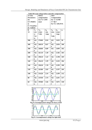
III. FUZZY LOGIC CONTROLLER
Fuzzy logic is a new control approach with great potential for real time applications [2] [3]. Fig.10
shows the structure of the fuzzy logic controller (FIS-Fuzzy inference system) in MATLAB Fuzzy logic
toolbox. [5][6].Load voltage and load current taken as input to fuzzy system. For a closed loop control, error](https://image.slidesharecdn.com/b230918-130704011010-phpapp02/85/B230918-4-320.jpg)
![Design, Modeling and Simulation of Fuzzy Controlled SVC for Transmission Line
www.ijesi.org 13 | P a g e
input can be selected as current, voltage or impedance, according to control type [7]. To get the linearity
triangular membership function is taken with 50% overlap. The output of fuzzy controller taken as the control
signal and the pulse generator provides synchronous firing pulses to thyristors as shown in fig.11. The Fuzzy
Logic is a rule based controller, where a set of rules represents a control decision mechanism to correct the
effect of certain causes coming from power system [8] [9]. In fuzzy logic, the five linguistic variables expressed
by fuzzy sets defined on their respective universes of discourse. Table-I shows the suggested membership
function rules of FC-TCR controller. The rule of this table can be chosen based on practical experience and
simulation results observed from the behavior of the system around its stable equilibrium points.
Fig.10. Structure of fuzzy logic controller
Fig.11. Single Phase equivalent circuit and fuzzy logic control structure of SVC
Table I. Membership function rules
Load voltage
Load
current
NL NM P PM PB
NL PB PB NM NM NL
NM PB PB NM P NL
P P PM NM NM P
PM NM P NM NM PM
PB NL NM NM NL NL
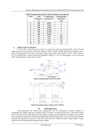
III HARDWARE IMPLEMENTATION
An available simple two-bus artificial transmission (λ/8) line model of 4π line segments with 750 km,
distributed parameters were used in this study. The line inductance 0.1mH /km, capacitance 0.01μf/km and the
line resistance 0.001Ω were used. Each π section is of 187km, 187km, 188km and 188 km. Supply voltage is
230V - 50 Hz having source internal resistance of 1 Ω connected to node A. Static load is connected at receiving
end B .The load resistance was varied to obtain the voltage variations at the receiving end. A shunt branch
consisting of inductor and capacitor is added to compensate the reactive power of transmission line. With the
change of load and due to Ferranti effect, the variations in voltages are observed at receiving end B of
transmission line [9] [10]. The practical values of shunt elements are varied for different loading conditions to
get both sending and receiving end voltages equal. As shown in Table II.](https://image.slidesharecdn.com/b230918-130704011010-phpapp02/85/B230918-5-320.jpg)
![Design, Modeling and Simulation of Fuzzy Controlled SVC for Transmission Line
www.ijesi.org 16 | P a g e
0 5000 10000 15000
-5
-4
-3
-2
-1
0
1
2
3
4
5
Fig.16. Inductor Current for firing angle 165 deg
V CONCLUSION
This paper presents an “online Fuzzy control scheme for SVC”and it can be concluded that the use of
fuzzy controlled SVC (FC-TCR) compensating device with the firing angle control is continuous, effective and
it is a simplest way of controlling the reactive power of transmission line. It is observed that SVC device was
able to compensate both over and under voltages. Compensating voltages are shown in Fig.17 and Fig.18. The
use of fuzzy logic has facilitated the closed loop control of system, by designing a set of rules, which decides the
firing angle given to SVC to attain the required voltage. With MATLAB simulations [4] [5] and actual testing it
is observed that SVC (FC-TCR) provides an effective reactive power control irrespective of load variations.
0 0.5 1 1.5 2 2.5 3 3.5 4 4.5
x 10
4
0
50
100
150
200
250
Fig.17. Compensated VR =VS (RMS voltage) for R=200Ω
0 5000 10000 15000
-400
-300
-200
-100
0
100
200
300
400
Fig.15. Uncompensated voltage for light load
0 5000 10000 15000
-5
-4
-3
-2
-1
0
1
2
3
4
5
Fig.16. Inductor Current for firing angle 165 deg
This paper presents an “online Fuzzy control scheme for SVC”and it can be concluded that the use of
fuzzy controlled SVC (FC-TCR) compensating device with the firing angle control is continuous, effective and
it is a simplest way of controlling the reactive power of transmission line. It is observed that SVC device was
able to compensate both over and under voltages. Compensating voltages are shown in Fig.17 and Fig.18. The
use of fuzzy logic has facilitated the closed loop control of system, by designing a set of rules, which decides the](https://image.slidesharecdn.com/b230918-130704011010-phpapp02/85/B230918-8-320.jpg)
![Design, Modeling and Simulation of Fuzzy Controlled SVC for Transmission Line
www.ijesi.org 17 | P a g e
firing angle given to SVC to attain the required voltage. With MATLAB simulations [4] [5] and actual testing it
is observed that SVC (FC-TCR) provides an effective reactive power control irrespective of load variations.
0 0.5 1 1.5 2 2.5 3 3.5 4 4.5
x 10
4
0
50
100
150
200
250
Fig.17. Compensated VR =VS (RMS voltage) for R=200Ω
0 5000 10000 15000
-300
-200
-100
0
100
200
300
400
Fig.18. Compensated VR=VS (instantaneous voltage) For R=200 Ω
REFERENCES
[1]. Narain. G. Hingorani, “Understanding FACTS, Concepts and Technology Of flexible AC Transmission Systems”, by IEEE Press
USA.
[2]. Bart Kosko, “Neural Networks and Fuzzy Systems A Dynamical Systems Approach to Machine Intelligence”, Prentice-Hall of
India New Delhi, June 1994.
[3]. Timothy J Ross, “Fuzzy Logic with Engineering Applications”, McGraw-Hill, Inc, New York, 1997.
[4]. Laboratory Manual for Transmission line and fuzzy Trainer Kit Of Electrical Engineering Department NIT Warangal
[5]. SIM Power System User Guide Version 4 MATLAB Manual
[6]. Periodicals and Conference Proceedings:
[7]. S.M.Sadeghzadeh M. Ehsan “ Improvement of Transient Stability Limit in Power System Transmission Lines Using Fuzzy
Control of FACTS Devices ,IEEE Transactions on Power System Vol.13 No.3 ,August 1998
[8]. Chuen Chien Lee “Fuzzy Logic in Control Systems: Fuzzy Logic Controller”. Part I and Part II. IEEE R. IEEE transactions on
system, man ,and cybernetics ,vol.20 March/April11990
[9]. A.M. Kulkarni, “Design of power system stabilizer for single-machine system using robust periodic output feedback controller”,
IEE Proceedings Part – C, Vol. 150, No. 2, pp. 211 – 216, March 2003. Technical Reports: Papers from Conference Proceedings
unpublished):
[10]. U.Yolac,T.Talcinoz Dept. of Electronic Eng.Nigde 51200,Turkey “Comparison Compariiison of Fuzzy Logic and PID Controls
For TCSC Using MATLAB”
[11]. Jaun Dixon ,Luis Moran, Jose Rodrfguz ,Ricardo Domke “Reactive power compensation technology state- of- art-
review”(invited paper)
[12]. Electrical Engineering Dept Pontifica Universidad Catolica De CHILE.
AUTHORS BIOGRAPHY
M.Sreerama, born in 1976 , he has got B.Tech degree in the year 1999 n and M.Tech degree in
the year of 2002, presently working as Assoc.Prof and HOD in the dept of EEE, Turbo
machinery institute of science and technology Hyderabad. His interested areas of research id
power systems, high voltage engineering and faults analysis in power systems and under ground
cables. He has 11 years of teaching experience in various engineering colleges at Hyderabad. He
has got Best Teacher Award.](https://image.slidesharecdn.com/b230918-130704011010-phpapp02/85/B230918-9-320.jpg)