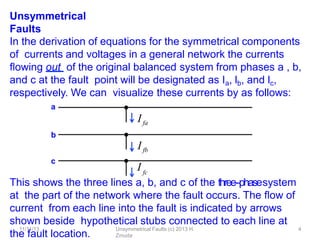
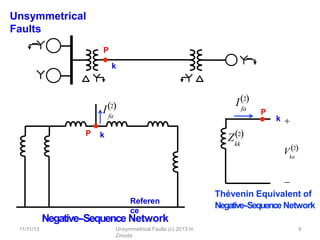
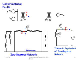
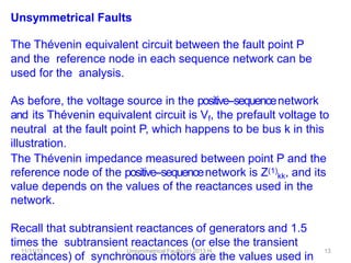
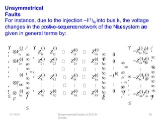
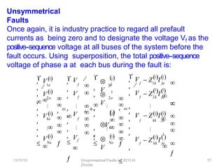
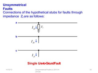
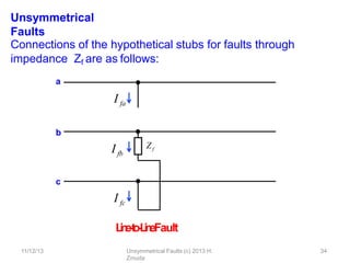
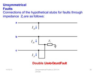
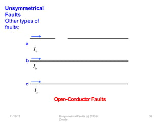
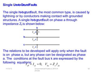
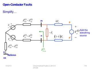
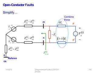
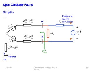
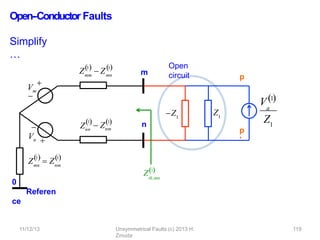
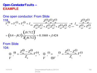
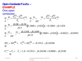
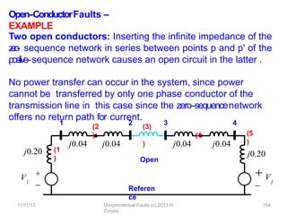
UNSYMMETRICAL
FAULTS
updated
11/11/13
11/11/13 Unsymmetrical Faults (c) 2013 H.
Zmuda
1
11/11/13 Unsymmetrical Faults (c) 2013 H.
Zmuda
2
Introductory Comments
Most of the faults that occur on power systems are
unsymmetrical faults, which may consist of unsymmetrical
short circuits, unsymmetrical faults through impedances, or
open conductors.
Unsymmetrical faults occur as single l
i
n
e
-‐
to
-‐g
rou
ndfaults, l
i
n
e
-
‐
t
o
-
‐
line
faults, or double l
i
n
e
-‐
to
-‐g
roun
dfaults. The path of the fault current
from line to line or line to ground may or may not contain
impedance. One or two open conductors result in
unsymmetrical faults, through either the breaking of one or
two conductors or the action of fuses and other devices that
may not open the three phases simultaneously.
11/11/13 Unsymmetrical Faults (c) 2013 H.
Zmuda
3
Introductory Comments
Since any unsymmetrical fault causes unbalanced currents to
flow in the system, the method of symmetrical components is
very used in the analysis to determine the currents and
voltages in all parts of the system aLer the occurrence of the
fault.
We will consider faults on a power system by applying
Thévenin's theorem, which allows us to find the current in
the fault by replacing the entire system by a single
generator and series impedance, and we will show how the
bus impedance matrix is applied to the analysis of
unsymmetrical faults.
Unsymmetrical
Faults
This shows the three lines a, b, and c of the three-‐phasesystem
at the part of the network where the fault occurs. The flow of
current from each line into the fault is indicated by arrows
shown beside hypothetical stubs connected to each line at
the fault location.
In the derivation of equations for the symmetrical components
of currents and voltages in a general network the currents
flowing out of the original balanced system from phases a , b,
and c at the fault point will be designated as Ia, lb, and lc,
respectively. We can visualize these currents by as follows:
a
Ifa
b
Ifb
I
11/11/13 Unsymmetrical Faults (c) 2013 H.
Zmuda
4
fc
c
11/11/13 Unsymmetrical Faults (c) 2013 H.
Zmuda
5
Unsymmetrical Faults
Appropriate connections of the stubs represent the various
types of fault. For instance, direct connection of stubs b and c
produces a l
i
n
e
-
‐
t
o
-
‐
l
i
n
efault through zero impedance.
The current in stub a is then zero, and lb equals -
‐lc.
The l
i
n
e
-‐
to
-‐g
roun
dvoltages at any bus j of the system during the
fault will be designated Vja, Vjb and Vjc and we shall continue
to use superscripts 1, 2, and 0, respectively, to denote positive-‐,
negative-‐,and zero-‐sequencequantities.
Thus, for example, V(1)
ja, V(2)
jb and V(0)
jc will denote,
respectively, the positive-‐,negative-‐,and zero-‐sequencecomponents
of the l
i
n
e
-
‐
t
o
-
‐
ground voltage Vja at bus j during the fault.
11/11/13 Unsymmetrical Faults (c) 2013 H.
Zmuda
6
Unsymmetrical Faults
The line-‐to-‐neutralvoltage of phase a at the fault point before the
fault occurs will be designated simply by Vf, which is a positive-‐
sequence voltage since the system is balanced.
We considered the prefault voltage Vf previously when
calculating the currents in a power system with a
symmetrical three-‐phase fault applied.
Unsymmetrical
Faults
Consider a single-‐linediagram of a power system containing two
synchronous machines. This simple system is sufficiently
general that the equations derived are applicable to any
balanced system regardless of the complexity. The point
where a fault is assumed to occur is marked P, and in this
example it is called bus k on the single-‐linediagram and in the
sequence networks.
Single line diagram of a balanced three-‐phase
system
P
k
11/11/13 Unsymmetrical Faults (c) 2013 H.
Zmuda
7
Unsymmetrical
Faults
P
k
Referen
ce
fa
I1
P  k
Vf

Positive-‐Sequence
Network

 Vf
P
fa
11/11/13 Unsymmetrical Faults (c) 2013 H.
Zmuda
8
I1
k
kk
Z1

Thévenin Equivalent of
Positive-‐Sequence Network

ka
V1
Unsymmetrical
Faults
Negative-‐Sequence Network
P
k
Referen
ce
P k
fa
I2
P
fa
11/11/13 Unsymmetrical Faults (c) 2013 H.
Zmuda
9
I2
k
kk
Z2

Thévenin Equivalent of
Negative-‐Sequence Network

ka
V2
Unsymmetrical
Faults
Reference
Zero-‐SequenceNetwork
P
k
P k
fa
I0
P
fa
I0
k
kk
Z0

Thévenin Equivalent
of Zero-‐Sequence
Network

ka
V0
11/11/13 Unsymmetrical Faults (c) 2013 H.
Zmuda
10
11/11/13 Unsymmetrical Faults (c) 2013 H.
Zmuda
11
Unsymmetrical Faults
Machines are represented by their subtransient internal
voltages in series with their subtransient reactances when
subtransient fault conditions are being studied.
Previously we used the bus impedance matrix composed of
positive-‐sequenceimpedances to determine currents and
voltages upon the occurrence of a symmetrical three-‐phase
fault. The method can be easily extended to apply to
unsymmetrical faults by
realizing that the negative-‐and zero-‐sequencenetworks also can b
e
represented by bus impedance matrices. The bus impedance
matrix will now be written symbolically for the positive-‐,negative-‐,
and zero-‐sequencenetworks in the following form…
11/11/13 Unsymmetrical Faults (c) 2013 H.
Zmuda
12
Unsymmetrical
Faults
bus
0,1,2
 

11 12
Z0,1,2
1k
Z0,1,2
1N
21
Z0,1,2 Z0,1,2
Zk1
0,1,2
  Z0,1,2 Z0,1,2
Z
0,1,2
 
 Z0,1,2
N1 N 2
Z0,1,2
Nk
Z0,1,2
22 2k 2N
k 2 kk kN
NN
Z0,1,2



 Z0,1,2






 Z0,1,2


Z0,1,2







Z0,1,2

11/11/13 Unsymmetrical Faults (c) 2013 H.
Zmuda
13
Unsymmetrical Faults
The Thévenin equivalent circuit between the fault point P
and the reference node in each sequence network can be
used for the analysis.
As before, the voltage source in the positive-‐sequencenetwork
and its Thévenin equivalent circuit is Vf, the prefault voltage to
neutral at the fault point P, which happens to be bus k in this
illustration.
The Thévenin impedance measured between point P and the
reference node of the positive-‐sequencenetwork is Z(1)
kk, and its
value depends on the values of the reactances used in the
network.
Recall that subtransient reactances of generators and 1.5
times the subtransient reactances (or else the transient
reactances) of synchronous motors are the values used in
11/11/13 Unsymmetrical Faults (c) 2013 H.
Zmuda
14
Unsymmetrical Faults
There are no negative-‐or zero-‐sequencecurrents flowing before
the fault occurs, and the prefault voltages are zero at all
buses of the negative-‐and zero-‐sequencenetworks. Therefore, the
prefault voltage between point P and the reference node is
zero in the negative-‐and zero-‐sequencenetworks and no
electromotive forces (emfs) appear in their Thévenin
equivalents.
The negative-‐and zero-‐sequenceimpedances between point P a
t
bus k and the reference node in the respective networks are
represented by the the impedances Z(2)
kk and Z(0)
kk, the
Diagonal elements of Z(2)
bus and Z(0)
bus, respectively.
11/11/13 Unsymmetrical Faults (c) 2013 H.
Zmuda
15
Unsymmetrical
Faults
Since Ifa is the current flowing from the system into the
fault, its symmetrical components flow out of the
respective sequence networks and their equivalent
circuits at point P, as shown.
Thus, the currents –I(1)
fa, –I(2)
g and –I(0)
fc represent injected
currents into the faulted bus k of the positive-‐, negative-‐, and zero--
‐sequencenetworks due to the fault.
These current injections cause voltage changes at the buses
of the positive-‐,negative-‐,and zero-‐sequencenetworks, which can be
calculated from the bus impedance matrices in the manner
similare to what we have done before.
11/11/13 Unsymmetrical Faults (c) 2013 H.
Zmuda
16
Unsymmetrical
Faults
For instance, due to the injection –I(1)
fa into bus k, the voltage
changes in the positive-‐sequencenetwork of the N
-
‐
b
u
ssystem are
given in general terms by:
1a
1
2a
1


V
Na
1




Vk
a



1



11 12 1k
Z1
1N
Z1
21 22
1 1
Z1 Z1
Zkk
N1 N 2
Z1
    1 1
 V Z Z

 V





  Z1





Nk
Z1
2k 2N
1 Z1
kN
NN
Z1
Z1


 Zk1 Zk 2




 Z1



















0
0
1

I
0
Z I
1k fa
1 1
Z I
2k fa
1 1
 
Zkk I fa
Z I
Nk fa







fa 

 



   


   
 

 



1 1
 


1 1 


11/11/13 Unsymmetrical Faults (c) 2013 H.
Zmuda
17
Unsymmetrical
Faults
Once again, it is industry practice to regard all prefault
currents as being zero and to designate the voltage Vf as the
positive-‐sequence voltage at all buses of the system before the
fault occurs. Using superposition, the total positive-‐sequence
voltage of phase a at each bus during the fault is:
1a
2a
Na




 Vka


 V 1




 V 1
 
1




 V 1

f
f
f





 V 
 
 V 


 V 
 
 
 
 Vf


V
1a
1

V
2a
1

V
Na
1




 

Vk
a



 



 


1





 Z I
f 1k fa
1 1
f
 Z I
2k fa
 
f
1
 Z I
Nk fa
 

 V



 
 V  Z I
f kk fa


 V



 V  
 
1 1



1 1
 


1
 

11/11/13 Unsymmetrical Faults (c) 2013 H.
Zmuda
18
Unsymmetrical
Faults
This is the same equation as found for symmetrical faults,
the only difference being the added superscripts and
subscripts denoting the positive-‐sequencecomponents of
the phase a quantities.
11/11/13 Unsymmetrical Faults (c) 2013 H.
Zmuda
19
Unsymmetrical
Faults
The negative-‐and zero-‐sequencevoltage changes due to the
fault at bus k of the N
-
‐
b
u
ssystem are similarly written with
the
superscripts changed accordingly. Because the prefault
voltages are zero in the negative-‐and zero-‐sequencenetworks, the
voltage changes express the total negative-‐and zero-‐sequence
voltages during the fault, namely,
1a
2a
Na




 Vka


 V 2



 V 2
 
2




 V 2

Z I
1k fa
2 2
Z I
2k fa
2 2
  
Zkk Ifa
Z I
Nk fa
  



 






    






2 2
 


2 2 



,
1a
2a
Na




 Vka


 V 0



 V 0
 
0




 V 0

Z I
1k fa
0 0
Z I
2k fa
0 0
  
Zkk Ifa
Z I
Nk fa
  
0 0
 


0 0 





 






    







11/11/13 Unsymmetrical Faults (c) 2013 H.
Zmuda
20
Unsymmetrical
Faults
When the fault is at bus k, note that only the entries in
columns k of Z(2)
bus and Z(0)
bus are involved in the calculations
of negative-‐and zero-‐sequencevoltages.
Thus, knowing the symmetrical components I(0)
fa, I(1)
fa and I(2)
fa
of the fault currents at bus k, we can determine the sequence
voltages at any bus j of the system from the jth rows of
1a
2a
Na




 Vka


 V 1 


 V 1 

1 



 V 1 
 Z I
f 1k fa
1 1
 Z I
f 2k fa

f
 Z I
Nk fa
 



 
 V  Z I
f kk fa


 V



 V    


 V 1 1 

1 1 



1 1
 


,
1a
2a
Na




 Vka


 V2 


 V2 

2 



 V2 
Z I
1k fa
2 2
Z I
2k fa

Zkk Ifa
Z I
Nk fa




 







  




 2 2
 
2 2 



2 2
 


,
1a
2a
Na




 Vka


 V 0 


 V 0 

0 



 V 0 
Z I
1k fa
0 0
Z I
2k fa

Zkk Ifa
Z I
Nk fa

0 0 



 







   




 0 0
 




0 0
 

11/11/13 Unsymmetrical Faults (c) 2013 H.
Zmuda
21
Unsymmetrical
Faults
That is, during the fault at bus k the voltages at any bus
j are:
If the prefault voltage at bus CD is not Vf, then simply replace
Vf in by the actual value of the prefault (positive-‐sequence)
voltage at that bus. Since Vf is by definition the actual
prefault voltage at the faulted bus k, we always have at that
bus:
and these are the terminal voltage equations for the
Thévenin equivalents of the sequence networks
previously shown.
V
0
ja jk fa
0 0
    
 Z I , V
1
ja f jk fa
1 1
  
 V  Z I , V
2
ja
 Z I
jk fa
2 2
    
Vka
0 0
  
kk fa
0

 Z I , Vka
1

f kk fa
1 1
 V  Z I , ka
2
  
V  Z I
kk fa
2 2
  
11/11/13 Unsymmetrical Faults (c) 2013 H.
Zmuda
22
Unsymmetrical Faults
It is important to remember that the currents I(0)
fa, I(1)
fa and I(2)
fa
are symmetrical-‐componentcurrents in the stubs hypothetically
attached to the system at the fault point.
These currents take on values determined by the particular
type of fault being studied, and once they have been
calculated, they
can be regarded as negative injections into the
corresponding sequence networks.
11/11/13 Unsymmetrical Faults (c) 2013 H.
Zmuda
23
Unsymmetrical
Faults
If the system has Δ
-
‐
Ytransformers, some of the sequence
voltages may have to be shiLed in phase angle before being
combined with other components to form the new bus
voltages of the faulted system. There are no phase shiLs
involved in
when the voltage Vf at the fault point is chosen as reference,
which is customary.
Vka
0 0
  
kk fa
0

 Z I , Vka
1

f kk fa
1 1
 V  Z I , ka
2
  
V  Z I
kk fa
2 2
  
Unsymmetrical
Faults
Δ
-
‐
Ytransformer with Positive-‐sequence Zero--
‐sequence
leakage impedance Z circuit circuit
The negative-‐sequencecircuit is the same as the positive-‐sequence
cir1
c1
/
u1
1
i/
t1
.3 Unsymmetrical Faults (c) 2013 H. Zmuda
2
n
m
In a system with Δ
-
‐
Ytransformers the open circuits encountered
in the zero-‐sequence network requires some care in the Zbus
building algorithm.
Consider, for instance, the solidly grounded Δ
-
‐
Y
transformer connected between buses m and n as
shown along with their positive and zero-‐sequencecircuits:
Z
m n
Reference
m
n
Reference
Z
11/12/13 Unsymmetrical Faults (c) 2013 H.
Zmuda
25
Unsymmetrical Faults
It is straightforward using the circuit representations shown
to generate the bus impedance matrices Zbus
(0,1,2). This will
be done subsequently.
Suppose, however, that we wish to represent removal of the
transformer connections from bus n in a computer algorithm
which cannot make use of circuit (schematic)
representations.
We can easily undo the connections to bus n in the positive-‐and
negative-‐sequencenetworks by applying the building algorithm
the Zbus
(1,2) matrices in the usual manner, i.e., by adding the
negative of the leakage impedance Z between buses m and
m in the positive-‐and negative-‐sequencenetworks. (Next slide)
Unsymmetrical
Faults
m n
Reference
Positive-‐sequence
circuit:
-
‐Z
Z
m n
Reference
11/12/13 Unsymmetrical Faults (c) 2013 H.
Zmuda
26


Unsymmetrical
Faults
This strategy does not apply to the zero-‐sequencematrix Zbus
(0) if
it has been formed directly from the schematic representation
shown. Adding -
‐Z between buses m and m does not remove
the z
e
r
o
-
‐sequence connection from bus n.
-
‐Z
m
n
Reference
Z
11/12/13 Unsymmetrical Faults (c) 2013 H.
Zmuda
27
Unsymmetrical
Faults
To permit uniform procedures for all sequence networks, one
strategy is to include an internal node p, as shown below.
Note that the leakage impedance is now subdivided into two
parts between node p and the other nodes as shown.
Connecting –Z/2 between buses n and p in each of the
sequence circuits will open the transformer connections to
bus n.
Z
m n m
n
Reference
Reference
Z
m n
Reference
Z/2
m
n
Reference
Z/2
Z/2
11/12/13 Unsymmetrical Faults (c) 2013 H.
Zmuda
28
p p Z/2




Unsymmetrical
Faults
Connecting –Z/2 between buses n and p in each of the
sequence circuits will open the transformer connections to
bus n.
-
‐Z/2 -
‐Z/2
m
n
Reference
Z/2
m
n
Reference
Z/2
Z/2
p
Z/2
p
m
n
Reference
Z/2
m
n
Reference
Z/2
p
11/12/13 Unsymmetrical Faults (c) 2013 H.
Zmuda
29
p




11/12/13 Unsymmetrical Faults (c) 2013 H.
Zmuda
30
Unsymmetrical Faults
The faults to be discussed in succeeding sections may
involve impedance Zf between lines and from one or two
lines to ground.
When Zf = 0, we have a direct short circuit, which is called a
bolted fault .
Although such direct short circuits result in the highest value of
fault current and are therefore the most conservative values to
use when determining the effects of anticipated faults, the
fault impedance is seldom zero.
11/12/13 Unsymmetrical Faults (c) 2013 H.
Zmuda
31
Unsymmetrical Faults
Most faults are the result of insulator flashovers, where the
impedance between the line and ground depends on the
resistance of the arc, of the tower itself, and of the tower
footing if ground wires are not used.
T
ower-‐footingresistances form the major part of the resistance
between line and ground and depend on the soil conditions.
The resistance of dry earth is 10 to 100 times the resistance
of swampy ground.
Unsymmetrical
Faults
Three-‐PhaseFault
Ifa
Ifb
Ifc
Connections of the hypothetical stubs for faults through
impedance Zf are as follows:
a
b
c
Zf
11/12/13 Unsymmetrical Faults (c) 2013 H.
Zmuda
32
Zf
Zf
Unsymmetrical
Faults
b
I fb
c
I fc
Single L
in
e
-‐
to
-‐
Gro
u
n
dFault
Ifa
Connections of the hypothetical stubs for faults through
impedance Zf are as follows:
a
Zf
11/12/13 Unsymmetrical Faults (c) 2013 H.
Zmuda
33
Unsymmetrical
Faults
Ifb
I fc
L
i
n
e
-
‐
t
o
-
‐
L
i
n
eFault
Connections of the hypothetical stubs for faults through
impedance Zf are as follows:
a
I fa
b
c
Zf
11/12/13 Unsymmetrical Faults (c) 2013 H.
Zmuda
34
Unsymmetrical
Faults
Ifb
I fc
Double L
in
e
-‐
to
-‐
Gro
u
n
dFault
Connections of the hypothetical stubs for faults through
impedance Zf are as follows:
a
I fa
b
c
Zf
11/12/13 Unsymmetrical Faults (c) 2013 H.
Zmuda
35
Unsymmetrical
Faults
Other types of
faults:
a
Ia
c
Ic
Open-‐Conductor Faults
b
Ib
11/12/13 Unsymmetrical Faults (c) 2013 H.
Zmuda
36
Unsymmetrical
Faults
Other types of
faults:
a
Ia
c
Ic
Open-‐Conductor Faults
b
Ib
11/12/13 Unsymmetrical Faults (c) 2013 H.
Zmuda
37
Unsymmetrical
Faults
A balanced system remains symmetrical aLer the occurrence
of a three-‐phasefault having the same impedance between
each line and a common point. Only positive-‐sequencecurrents
flow. With the fault impedance Zf equal in all phases, as in a
three-‐phasefault, we simply add impedance Zf to the usual
(positive-‐sequence) Thévenin equivalent circuit of the system at
the fault bus k and calculate the fault current from the
equation:
For each of the other types of faults, formal derivations of the
equations for the symmetrical-‐componentcurrents follow. In
each case the fault point P is designated as bus k.
fa
1

I 
Vf
1

Z  Z
kk f
11/12/13 Unsymmetrical Faults (c) 2013 H.
Zmuda
38
Exampl
e
Two synchronous machines are connected through three--
‐phasetransformers to the transmission line as shown.
The ratings and reactances of the machines and
transformers are:
Machine 1 &
2:
100MVA, 20 kV, Xd” = X1 = X2 =
20%
X0 = 4%, Xn =
5%
Transformers T1 & T2: 100 MVA, 20Δ/345Y kV, X
= 8%
On a chosen base of 100 MVA, 345 kV in the
transmission line circuit the line reactances are X1 = X2
= 15% and X0 = 50%.
1 T1 2 3 T2 4
Machine 1 Machine 2
11/12/13 Unsymmetrical Faults (c) 2013 H.
Zmuda
39
Exampl
e
Positive-‐and negative-‐sequence circuit:
The ratings and reactances of the machines and
transformers are: Machine 1 & 2: 100MVA, 20 kV, Xd” =
X1 = X2 = 20%
X0 = 4%, Xn =5%
Transformers T1, T2: 100 MVA, 20Δ/345Y kV, X = 8% (split as
4% + 4%) Transmission line reactances are X1 = X2 = 15% and
X0 = 50%.
1 2
11/12/13 Unsymmetrical Faults (c) 2013 H.
Zmuda
40
3 4
 V

f
Vf


j0.20 j0.20
j0.04 j0.04 j0.15 j0.04 j0.04
Referen
ce
(1
)
(2)
(3
)
(4
) (5
)
Exampl
e
Add branch (1):
Z
1
11/12/13 Unsymmetrical Faults (c) 2013 H.
Zmuda
41
2 (3) 3 4
 V

f
Vf


j0.20
j0.04 j0.15
j0.04 j0.04 j0.04
Referen
ce
(1
)
(5)
j0.20
(2
)
(4
)
1
1,2
 
 
j0.20
 
1,2 j0.20
j0.20
Add branch
(2):

Z2 



j0.20
j0.20  j0.08








j0.20

j0.20

j0.20 j0.28


Exampl
e
1
11/12/13 Unsymmetrical Faults (c) 2013 H.
Zmuda
42
2 (3) 3 4
 V

f
Vf


j0.20
j0.04 j0.15
j0.04 j0.04 j0.04
Referen
ce
(1
)
(5)
j0.20
(2
)
(4
)
3 



Add branch
(3):
 j0.20
Z1,2 

j0.20
 j0.20
j0.20
j0.28
j0.28
j0.20
j0.28
j0.28  j0.15
 



 
 
j0.20
j0.20
j0.20
j0.20
j0.28
j0.28
j0.20
j0.28
j0.43





Exampl
e
1
11/12/13 Unsymmetrical Faults (c) 2013 H.
Zmuda
43
2 (3) 3 4
 V

f
Vf


j0.20
j0.04 j0.15
j0.04 j0.04 j0.04
Referen
ce
(1
)
(5)
j0.20
(2
)
(4
)
Z4
1,2
 

j0.20
j0.20
j0.20
j0.20
j0.20
j0.28
j0.28
j0.28
Add branch
(4):

j0.20
j0.28
j0.43
j0.43
j0.20
j0.28
j0.43
j0.43 j0.08



















j0.20
j0.20
j0.20
j0.20
j0.20
j0.28
j0.28
j0.28
j0.20

j0.20

j0.28 j0.28

j0.43
j0.43
j0.43


j0.51




Exampl
e
Add branch
(5):

1
11/12/13 Unsymmetrical Faults (c) 2013 H.
Zmuda
44
2 (3) 3 4
 V

f
Vf


j0.20
j0.04 j0.15
j0.04 j0.04 j0.04
Referen
ce
(1
)
(5)
j0.20
(2
)
(4
)
Z4
1,2
 

j0.20 j0.28 j0.28 j0.28
j0.20 j0.28 j0.43 j0.43
j0.20 j0.28 j0.43 j0.51






j0.20 j0.20 j0.20 j0.20 






Znew
ij  Zij
Z Z
 ik kj
Z  Z
kk b
Exampl
e
11/12/13 Unsymmetrical Faults (c) 2013 H.
Zmuda
45
Exampl
e
Z1,2:
bus
11/12/13 Unsymmetrical Faults (c) 2013 H.
Zmuda
46
Example Zero-‐sequence circuit:
j0.04 1 3 j0.08 4
j0.04
Reference
The ratings and reactances of the machines and
transformers are: Machine 1 & 2: 100MVA, 20 kV, Xd” =
X1 = X2 = 20%
X0 = 4%, Xn = 5%
Transformers T1 & T2: 100 MVA, 20Δ/345Y kV, X
= 8% Transmission line reactances are X1 = X2 = 15%
and X0 = 50%.
j0.5 j0.04
3Xn  j0.15
(1
) (2
)
(3
)
(4
)
(5
)
(6
)
3Xn  j0.15
See Slide
199 of
Symmetrical
Components
Transform
er Node
Bus
Transform
er Node
Bus
See Slide
196 of
Symmetrical
11/12/13 Unsymmetrical Faults (c) 2013 H.
Zmuda
47
Components
j0.04 2
Exampl
e
1
11/12/13 Unsymmetrical Faults (c) 2013 H.
Zmuda
48
2 3 j0.08 4
j0.08
Referen
ce
j0.5
j0.19
j0.19
(1
)
(2
)
(3
)
(4
)
(5
)
Exampl
e
Add branch (1):
Z
Add branch
(2):
1
11/12/13 Unsymmetrical Faults (c) 2013 H.
Zmuda
49
2 3 j0.08 4
j0.08
Referen
ce
j0.5
j0.19
j0.19
(1
)
(2
)
(3
)
(4
)
(5
)
0

1

 
j0.19

2
0


Z 
 



j0.19 0
0 j0.08


3
0

Z 
j0.19 0
0 j0.08
0 j0.08
Add branch
(3):

0
j0.08







j0.08 j0.5


Exampl
e
Add branch
(5):
1
11/12/13 Unsymmetrical Faults (c) 2013 H.
Zmuda
50
2 3 j0.08 4
j0.08
Referen
ce
j0.5
j0.19
j0.19
(1
)
(2
)
(3
)
(4
)
(5
)
Z
0


j0.19 0 0 0
0 j0.08 j0.08 0
0 j0.08 j0.58 0
0 0 0 j0.19



bus










11/12/13 Unsymmetrical Faults (c) 2013 H.
Zmuda
51
Exampl
e
We’ll use these in subsequent
examples.
Z
0





bus 


j0.19 0 0 0
0 j0.08 j0.08 0
0 j0.08 j0.58 0
0 0 0 j0.19







Z
1,2
 




bus 


j0.1437 j0.1211 j0.0789 j0.0563
j0.1211 j0.1696 j0.1104 j0.0789
j0.0789 j0.1104 j0.1696 j0.1211
j0.0563 j0.0789 j0.1211 j0.1437







Single L
in
e
-‐
to
-‐
Gro
u
n
dFaults
The single l
i
n
e
-‐
to
-‐g
roundfault, the most common type, is caused b
y
lightning or by conductors making contact with grounded
structures. A single l
i
n
e
-‐
to
-‐g
roundfault on phase a through
impedance Zf is shown below:
The relations to be developed will apply only when the fault
is on phase a, but any phase can be designated as phase
a. The conditions at the fault bus k are expressed by the
following equations:
I fa
b
I fb
c
I fc
a
Z f
k
11/12/13 Unsymmetrical Faults (c) 2013 H.
Zmuda
52
fb fc ka
I  I  0, V  Z I
f fa
11/12/13 Unsymmetrical Faults (c) 2013 H.
Zmuda
53
Single L
in
e
-‐
to
-‐
Gro
u
n
dFaults
The symmetrical components of the current are, with I fb  I fc
 0:
But recall from Slide
21:
Thus
:
Vka
0 0
  
kk fa
0

 Z I , Vka
1

f kk fa
1 1
 
 V  Z I , Vka
2

 Z I
kk fa
2 2
  
Vka
0

kk fa
0 0
  
 Z I , Vka
1

f kk fa
1 0
 V  Z I , ka
2
   
V  Z I
kk fa
2 0
  
fa
fa
I1
I
 I0
 

2





 fa




1 1
a a2
a2
a

1
3
 1
 1

1  0
0
I fa







 




 I fa
0
fa
1
 I  I
2
fa
   

I fa
3
Single L
in
e
-‐
to
-‐
Gro
u
n
dFaults
Summing, and noting that
V
This has the circuit representation shown on the next
slide.
V V
ka ka ka
0 1
V Vka
2
   
f
 V  Z
0
kk

 Z
1
kk
 Z
2
kk
 
 I fa
0

 3Z I
f fa
0

ka
 3Z I
f fa
0

fa
Solve for I
0
I fa
0
fa
1
 I  I
2
fa
   

Vf
Z
0
kk kk
1
kk
2
   
 Z  Z 3Z f
11/12/13 Unsymmetrical Faults (c) 2013 H.
Zmuda
54
Single L
in
e
-‐
to
-‐
Gro
u
n
dFaults
Vf


kk
Z1
kk
Z2
kk
Z0
3Z f
fa
I1
fa
I2
fa
I0
I
11/12/13 Unsymmetrical Faults (c) 2013 H.
Zmuda
55
fa
0
fa
1
 I  I
2
fa
   
k
k
k

ka
 V1

ka
 V0

ka
 V2
11/12/13 Unsymmetrical Faults (c) 2013 H.
Zmuda
56
Single L
in
e
-‐
to
-‐
Gro
u
n
dFaults
The last result are the fault current equations particular to the
single l
i
n
e
-‐
to
-‐g
roundfault through impedance Zf and they are used
with the symmetrical-‐componentrelations to determine all the
voltages and currents at the fault point P.
If the Thévenin equivalent circuits of the three sequence
networks of the system are connected in series, as shown
on the previous slide, we see that the resulting currents and
voltages satisfy the above equations – for the Thévenin
impedances looking into the three sequence networks at
fault bus k are then in series with
the fault impedance 3Zf and the prefault voltage source Vf.
11/12/13 Unsymmetrical Faults (c) 2013 H.
Zmuda
57
Single L
in
e
-‐
to
-‐
Gro
u
n
dFaults
With the equivalent circuits so connected, the voltage across
each sequence network is the corresponding symmetrical
component of the voltage Vka at the fault bus k, and the
current injected into each sequence network at bus k is the
negative of the corresponding sequence current in the fault.
The series connection of the Thévenin equivalents of the
sequence networks, as shown on Slide 55 is a convenient
means of remembering the equations for the solution of the
single l
i
n
e
-
‐
t
o
-
‐
ground fault, for all the necessary equations for the
fault point can be determined from the sequence-‐network
connection.
11/12/13 Unsymmetrical Faults (c) 2013 H.
Zmuda
58
Single L
in
e
-‐
to
-‐
Gro
u
n
dFaults
Once the sequence components of the fault currents are
known, the components of voltages at all other buses of the
system can be determined from the bus impedance matrices
of the sequence networks according to Slide 21, namely:
V
V
V
0
ja
 Z I
jk fa
0 0
    
1
ja

f
 V  Z I
jk fa
1 1
 
2
ja

 Z I
jk fa
2 2
  
EXAMPLE – Single L
in
e
-‐
to
-‐
Gro
u
n
dFaults
The ratings and reactances of the machines and
transformers are:
Machine 1 &
2:
100MVA, 20 kV, Xd” = X1 = X2 =
20%
X0 = 4%, Xn =
5%
Transformers T1 & T2: 100 MVA, 20Y/345Y kV, X
= 8%
Two synchronous machines are connected through three--
‐phasetransformers to the transmission line as shown.
1 T1 2 3 T2 4
Machine
1
Machine
2
11/12/13 Unsymmetrical Faults (c) 2013 H.
Zmuda
59
11/12/13 Unsymmetrical Faults (c) 2013 H.
Zmuda
60
EXAMPLE – Single L
in
e
-‐
to
-‐
Gro
u
n
dFaults
Both transformers are solidly grounded on on two sides. On a
chosen base of 100 MVA, 345 kV in the transmission line
circuit the line reactances are X1 = X2 = 15 % and X0 = 50 %.
The system is operating at nominal voltage without prefault
currents when a bolted (Zf = 0) single l
i
n
e
-‐
to-‐
g
ro
u
n
dfault occurs o
n
phase A at bus 3.
Using the bus impedance matrix for each of the three
sequence networks, determine the subtransient current to
ground at the fault, the l
i
n
e
-‐
to
-‐groundvoltages at the terminals of
machine 2, andthe subtransient current out of phase c of
machine 2.
EXAMPLE – Single L
in
e
-‐
to
-‐
Gro
u
n
dFaults
The system is the same as on Slide 39, except that the
transformers are now Y
-
‐
Yconnected. Therefore, we can
continue to use Zbus
(1,2) from Slide 51, however, because the
transformers are solidly grounded on both sides, the zero--
‐sequencenetwork is fully connected, as shown below, and has
the bus impedance matrix
1 2 3 4
j0.04 j0.08 j0.15 j0.08 j0.04
j0.15 j0.15
11/12/13 Unsymmetrical Faults (c) 2013 H.
Zmuda
61
Referen
ce
EXAMPLE – Single L
in
e
-‐
to
-‐
Gro
u
n
dFaults
2
11/12/13 Unsymmetrical Faults (c) 2013 H.
Zmuda
62
3 4
j0.15
j0.15
j0.15
The bus impedance matrix
is:
1
j0.04 j0.08
j0.08 j0.04
Referen
ce
Zbus
0


j0.1553 j0.1407 j0.0493 j0.0347
j0.1407 j0.1999 j0.0701 j0.0493
j0.0493 j0.0701 j0.1999 j0.1407
j0.0347 j0.0493 j0.1407 j0.1553














EXAMPLE – Single L
in
e
-‐
to
-‐
Gro
u
n
dFaults
Since the l
i
n
e
-‐
to-‐
groundfault is at bus 3
:
The total current in the fault
is:
f
V 1.0 33
Z1
Z2
33
33
Z0
f
3Z  0
fA
1
I 
fA
I2
fA
I0
IfA
3
k
k
k


V3a
1

3a
 V0

3a
 V2

0

Z 



bus

Z

j0.1553 j0.1407 j0.0493 j0.0347
j0.1407 j0.1999 j0.0701 j0.0493
j0.0493 j0.0701 j0.1999 j0.1407
j0.0347 j0.0493 j0.1407 j0.1553
j0.1437 j0.1211 j0.0789 j0.0563
j0.1211 j0.1696 j0.1104 j0.0789
j0.0789 j0.1104 j0.1696 j0.1211
j0.0563 j0.0789 j0.1211 j0.1437




1,2 
bus 

















I fA
0

 I fA
1
fA
2
 
 I 
Vf
kk
0
kk
1
kk
2
   
Z  Z  Z 3Z f

1
j0.1999  j1.696  j1.696  0
  j1.8549
11/12/13 Unsymmetrical Faults (c) 2013 H.
Zmuda
63
fA fA
0

 I  3I   j5.5648
EXAMPLE – Single L
in
e
-‐
to
-‐
Gro
u
n
dFaults
Since the base current in the high-‐voltagetransmission line
is:
amp
s
Then:
amp
s
The p
h
a
se
-‐asequence voltages at bus 4, the terminals of
machine 2, are (from Slide 21 with k = 3 and j = 4):
per
unit
base
3 345
I 
100,000
 167.35
11/12/13 Unsymmetrical Faults (c) 2013 H.
Zmuda
64
I fA   j5.5648167.35 931270
V4a 43 fA
0 0 0
    
 Z I    
j0.1407  j1.8549  0.261
V4a
1

f 43 fA
1 1
 
  
 V  Z I  1 j0.1211  j1.8549  0.7754
V4a
2

 Z I
43 fA
2 2
  
  
  j0.1211  j1.8549  0.2246
11/12/13 Unsymmetrical Faults (c) 2013 H.
Zmuda
65
EXAMPLE – Single L
in
e
-‐
to
-‐
Gro
u
n
dFaults
Note that the subscripts A and a denote voltages in the high--
‐voltageand low-‐voltagecircuits, respectively, of the Y
-
‐
Yconnected
transformer. No phase shiL is involved.
From the symmetrical components we can calculate the a
-
‐
b
-
‐
c
l
i
n
e
-
‐
to-
‐groundvoltages at bus 4 as:
per
unit
4a
4b
4c


V
 V 

 V 



1 
1 1 1
1 a2
a
a a2
3
1


V4a
0
4a
4a






  
 


 V 2
 

 V 1 

1 
1 1 1
1 a2
a
a a2
3
1









0.261
0.7754



0.2246


0.2898








0.5346  j0.8660


0.5346  j0.8660

EXAMPLE – Single L
in
e
-‐
to
-‐
Gro
u
n
dFaults
To express the l
i
n
e
-‐
to-‐g
roundvoltages of machine 2 (in kV) multiply
by 20/31/2:
k
V
4b
4c


 V 
4a


 
V 


 V 
20
0.2898
11/12/13 Unsymmetrical Faults (c) 2013 H.
Zmuda
66
0.5346  j0.8660



3






3.346
1.0187121.8






0.5346  j0.8660  1.0187 121.8


EXAMPLE – Single L
in
e
-‐
to
-‐
Gro
u
n
dFaults
To determine p
h
a
s
e-‐ccurrent out of machine 2 we must first
calculate the symmetrical components of the p
h
a
se
-‐acurrent in
the branches representing the machine in the sequence
networks.
From the zero-‐sequencecircuit, the zero-‐sequencecurrent out of
the machine
is:
per
unit
1 2 3 4
j0.15
j0.04
j0.15
j0.08 j0.15 j0.08 j0.04
Referen
ce

4a
V0

a
I0
a
0

I   4a
V0
0

jX j0.04
0.261
  j6.525
11/12/13 Unsymmetrical Faults (c) 2013 H.
Zmuda
67
EXAMPLE – Single L
in
e
-‐
to
-‐
Gro
u
n
dFaults
per
unit
a
1
I 
V V1
 f 4a
jX


1 0.7754
j0.2
  j1.123
 V

f
Vf


j0.20 j0.20
j0.04 j0.04 j0.15 j0.04 j0.04
Referen
ce

4a
V1,2

a
Similarly for the positive-‐and negative-‐sequence currents:
1 2 3 4
I1,2
a
2

I   4a
V1
jX2

0.2246
j0.2
  j1.123
11/12/13 Unsymmetrical Faults (c) 2013 H.
Zmuda
68
EXAMPLE – Single L
in
e
-‐
to
-‐
Gro
u
n
dFaults
The p
h
a
se
-‐
ccurrent in machine 2 is
per
unit
Since the base current in the machine
circuit is:
amp
s
c a
0 1
   2
I  I  aI  a I
a a
2

  j6.525 a j1.123 a2
j1.123
  j5.402
Ibase
3 20

100,000
 2886.751
amps
Ic 15,994
11/12/13 Unsymmetrical Faults (c) 2013 H.
Zmuda
69
L
i
n
e
-
‐
t
o
-
‐
L
i
n
eFaults
To represent a l
i
n
e
-
‐
t
o
-
‐
l
i
n
efault through impedance Zf the
hypothetical stubs on the three lines at the fault are
connected as shown. Bus k is again the fault point P, and
without any loss of generality, the l
i
n
e
-
‐
t
o
-
‐
l
i
n
efault is regarded as
being on phases b and c. Clearly:
Ifb
11/12/13 Unsymmetrical Faults (c) 2013 H.
Zmuda
70
Ifc
a
b
c
Zf
k
I fa I  0
fa
k
k
I fb  I fc
Vkb Vkc
 Z I
f fb
11/12/13 Unsymmetrical Faults (c) 2013 H.
Zmuda
71
L
i
n
e
-
‐
t
o
-
‐
L
i
n
eFaults
Substitutin
g:
The voltages throughout the zero-‐sequencenetwork must be
zero
current is not being injected into that network due to the
fault. Hence, l
i
n
e
-
‐
t
o
-
‐
l
i
n
efault calculations do not involve the z
e
r
o
-
‐
sequence network, which remains the same as before the
fault -
‐adead network.
since there are no zero-‐sequencesources, and
because I
fa
fa
I1




 I0
 

2


I fa




 1
1
1 1
a a2
a2
a


1
3
  1  I fc








 0 
I

fb 



 I
 I
fa
0

 0
 I
fa
1
 2
fa

fa
0

 0,
L
i
n
e
-
‐
t
o
-
‐
L
i
n
eFaults
equivalents of the positive-‐and negative-‐sequencenetworks i
n
parallel, as shown:
To satisfy the requirement
that I
1

 I we connect the
Thévenin
fa fa
2

Vf


kk
Z1
kk
Z2
Z f
fa
I1
fa
I2
k

ka
V1

k
11/12/13 Unsymmetrical Faults (c) 2013 H.
Zmuda
72

ka
V2

Referen
ce
11/12/13 Unsymmetrical Faults (c) 2013 H.
Zmuda
73
L
i
n
e
-
‐
t
o
-
‐
L
i
n
eFaults
To show that this connection of the networks also
satisfies the voltage equation:
we now expand each side of that equation separately as
follows:
and
:
V V  Z I
kb kc f fb
kb kc
V V  Vkb
1
kb
2
 
 
V  Vkc
1
Vkc
2
 
 
 Vkb
1

Vkc
1

 Vkb
2
Vkc
2
  
   
2
ka
1

 a V  a  2
   
a Vka
2

 a
 a2
  ka
 a V Vka
1 2
 
 
f fb
Z I  Z f fb
1
I  I
2
fb
 
f
2
fa
1
 Z a I  aI fa
2
 
   
11/12/13 Unsymmetrical Faults (c) 2013 H.
Zmuda
74
L
i
n
e
-
‐
t
o
-
‐
L
i
n
eFaults
Equate both terms and
set:
But this is precisely the voltage drop across Zf in the figure on
Slide 66.
kb kc
2
 
V V  a  a Vka
1
ka
2
 
  f fb f
2
V  Z I  Z a I fa
1
 aI
2
fa
 
 
2
 
 a  a Vka
1
ka
2
 
  f
2
 
V  Z a  a I fa
1

ka
1
V Vka
2
 
 Z I
f fa
1

I fa
1

 I
2
fa

11/12/13 Unsymmetrical Faults (c) 2013 H.
Zmuda
75
L
i
n
e
-
‐
t
o
-
‐
L
i
n
eFaults
Thus, all the fault conditions are satisfied by connecting
the positive-‐and negative-‐sequencenetworks in parallel
through impedance Zf as was shown.
The zero-‐sequencenetwork is inactive and does not enter into
the l
i
n
e
-
‐
t
o
-
‐
l
i
n
ecalculations. The equation for the positive-‐sequence
current in the fault can be determined directly from the circuit
as:
11/12/13 Unsymmetrical Faults (c) 2013 H.
Zmuda
76
Example – L
i
n
e
-
‐
t
o
-
‐
L
i
n
eFaults
The same system as before is operating at nominal system
voltage without prefault currents when a bolted l
i
n
e
-
‐
t
o
-
‐
l
i
n
efault
occurs at bus 3. Determine the currents in the fault, the l
i
n
e
-
‐
t
o
-
‐
l
i
n
e
voltage a
tthe fault bus, and the l
i
n
e
-
‐
t
o
-
‐
l
i
n
evoltages at the terminals
of machine 2.
Example – L
i
n
e
-
‐
t
o
-
‐
L
i
n
eFaults
Note that we will not need the zero-‐sequencebus
impedance matrix since the fault is l
i
n
e
-
‐
t
o
-
‐
l
i
n
e(see Slide 71).
From the
circuit:
f
33
The Thévenin equivalent circuit for the positive-‐and n
e
g
a
t
i
v
e
-
‐
sequence is: Z1
33
Z2
f
Z  0
IfA
1
fA
3

V3A
1

3
 I2
V3A
2

Referen
ce
 V
1,2
Z 
j0.1437 j0.1211 j0.0789 j0.0563
j0.1211 j0.1696 j0.1104 j0.0789
j0.0789 j0.1104 j0.1696 j0.1211
j0.0563 j0.0789 j0.1211 j0.1437



bus











I fA fA
1 2
 
 I 
Vf
33
1
Z  Z33
2
  2  j0.1696
11/12/13 Unsymmetrical Faults (c) 2013 H.
Zmuda
77

1.0
  j2.9481 per unit
11/12/13 Unsymmetrical Faults (c) 2013 H.
Zmuda
78
Example – L
i
n
e
-
‐
t
o
-
‐
L
i
n
eFaults
Sinc
e
(Uppercase since the fault is in the high--
‐voltage
transmission
line)
Then I
and
since
Then I fA 0
Also I per
unit
an
d
per
unit
Multiply these by Ibase = 167.35 A to get the actual
currents.
fA
 I fA
1
 I fA
2
 
I fA
0

 0
I fA
1

 I fA
2

1
fB fA fA
2
2  
 a I  aI  5.1061
I fC  I fB  5.1061
11/12/13 Unsymmetrical Faults (c) 2013 H.
Zmuda
79
Example – L
i
n
e
-
‐
t
o
-
‐
L
i
n
eFaults
The symmetrical components of p
h
a
s
e
-‐Avoltage to ground at
bus 3are:
per
unit
V3A
0

 0
V3A
1
3A
2
 
 V  1 Z I
kk fA
1 1
 
 1 j0.1696  j2.9481
  
 0.5  j0
11/12/13 Unsymmetrical Faults (c) 2013 H.
Zmuda
80
Example – L
i
n
e
-
‐
t
o
-
‐
L
i
n
eFaults
The l
i
n
e
-‐
to
-‐g
roun
dvoltages at fault bus 3 are:
V3C  V3B 0.5
all per unit
V V
3A 3A 3A
0 1
V V3A
2
   
 0  0.5 0.5  1.0
V V
3B 3B
0

 a V3B
1
2   2V3B
2
 2
 0 a 0.5 a  0.5  0.5
11/12/13 Unsymmetrical Faults (c) 2013 H.
Zmuda
81
Example – L
i
n
e
-
‐
t
o
-
‐
L
i
n
eFaults
The l
i
n
e
-
‐
t
o
-
‐
l
i
n
evoltages at fault bus 3 are:
V3,AB  V3A V3B  1 j0 0.5 j0 1.5
V3,BC  V3B V3C  0.5 j0 0.5 j0 0
all per unit. Multiply these by 345/31/2 to obtain the actual
voltage.
V3,CA V3C
 V3 A  0.5  j0 1 j0 1.5
11/12/13 Unsymmetrical Faults (c) 2013 H.
Zmuda
82
Example – L
i
n
e
-
‐
t
o
-
‐
L
i
n
eFaults
For the moment, let us avoid phase shiLs due to the Δ
-
‐
Y
transformer connected to machine 2 and calculate the
sequence voltages of phase A at bus 4 using the the results
from Slide 21
with k = 3 and j = 4:
per
unit
Vja jk fa ja f jk fa

0  Z0I0, V 1V  Z1I1, V 2  Z2I2
ja jk fa
0 Z 0I0
V4a 43 fa
0
V4a
1

f jk fa
1 1
 
 V  Z I 1 j0.1211 j2.9481 0.643
V4a
2

 Z I
43 fa
2 2
  
  
  j0.1211  j2.9481  0.357
11/12/13 Unsymmetrical Faults (c) 2013 H.
Zmuda
83
Example – L
i
n
e
-
‐
t
o
-
‐
L
i
n
eFaults
To account for phase shiLs in stepping down from the high--
‐voltagetransmission line to the low-‐voltageterminals of machine
2, we must retard the positive-‐sequencevoltage and advance
the negative-‐sequencevoltage by 30°. At machine 2 terminals,
indicated by lowercase a, the voltages are:
V4a 43 fa
0 0 0
    
 Z I  0
V4a
1
4a
1
 
 V   30  0.643  30  0.5569  j0.3215
V4a
2

4a
2

 V 30  0.35730  0.3092 j0.1785
V V
4a 4a
0

4a
1
V V4a
2
 
 0.8861 j0.1430  0.8778 9.4
11/12/13 Unsymmetrical Faults (c) 2013 H.
Zmuda
84
Example – L
i
n
e
-
‐
t
o
-
‐
L
i
n
eFaults
P
h
a
se-‐bvoltages at the terminals of machine 2
are:
V4b
0
4a
0
  
 V  0
V4b
1
 2
 a V4a
1

1240 0.643  30  0.5569  j0.3215
V4b
2

 aV4a
2

 1120 0.35730  0.3092  j0.1785
V V
4b 4b
0

4b
1
V V4b
2
 
 0.8861 j0.1430  0.8778170.6
11/12/13 Unsymmetrical Faults (c) 2013 H.
Zmuda
85
Example – L
i
n
e
-
‐
t
o
-
‐
L
i
n
eFaults
P
h
a
se-‐
cvoltages at the terminals of machine 2
are:
V4c
0
4a
0
  
 V  0
V4c
1

 aV4a
1

 1120 0.643  30  0.64390
V4c
2
 2
 a V4a
2

 1240 0.35730  0.357  90
V V
4c 4c
0

4c
1
V V4c
2
 
 j0.286
Example – L
i
n
e
-
‐
t
o
-
‐
L
i
n
eFaults
L
i
n
e
-
‐
t
o
-
‐
l
i
n
evoltages at the terminals of machine 2 are:
per
unit
For the voltage, multiply by 20
kV/31/2
k
V
V4,ab 4a
0 0
4b
0
    
V4,bc
0

V4b
0
V4c
0
  
0.8661 j0.429
j0.429
V
0

 V V
4,ca 4c 4a
0 0
  
 V V 1.7322
 
 0.8661
V4,ab
0
 20
3
 1.7322   20
11/12/13 Unsymmetrical Faults (c) 2013 H.
Zmuda
86
V4,bc
0

11.2 153.65
 11.2153.65
V4,ca
0

Ifa
Ifb
b
c
Zf
I fa 0
11/12/13 Unsymmetrical Faults (c) 2013 H.
Zmuda
87
Double L
in
e
-‐
to
-‐
Gro
u
n
dFaults
Again it is clear, with fault taken on phases b and c,
that the relations at fault bus k are:
k
a
Vkb  Vkc  Z f Ifb  I fc 
k
Ifc
k
11/12/13 Unsymmetrical Faults (c) 2013 H.
Zmuda
88
Double L
in
e
-‐
to
-‐
Gro
u
n
dFaults
Thus Vkb  Vkc  Z
Substituting into:
fa
Since I  0 I fa
0


1
3 fa fb
I  I  I fc
 
1
3 fb
I  I fc
 
f fb fc
 
I  I  3Z I
f fa
0

ka
ka
ka


 V0





 V2
 

 V1 


1 
1 1 1
1 a a2
a2
a
3
 1
ka
kb
kc




V
 V 
 
 V 




1 
1 1 1
1 a a2
a2
a
3
 1
ka
kb
kb
 V




V
 V 
 




Double L
in
e
-‐
to
-‐
Gro
u
n
dFaults
Expanding the second and third
equations:
ka
ka
ka


 V0





 V2

 V1 


1 
1 1 1
1 a a2
a2
a
3
 1


1
3
ka
kb
kb
 V




V
 V 
 




Vka
1

 2
 
a  a Vkb
Vka
2 1
3
 a2
 aV
11/12/13 Unsymmetrical Faults (c) 2013 H.
Zmuda
89
kb
Vka
1

Vka
2

11/12/13 Unsymmetrical Faults (c) 2013 H.
Zmuda
90
Double L
in
e
-‐
to
-‐
Gro
u
n
dFaults
From the first
equation:
recall: Vkb  Vkc  Z f Ifb  Ifc 
ka
ka
ka

 V0


 
 V2

 V1 


1 
1 1 1
1 a a2
a2
a
3
 1

3V
ka
kb
kb




V
 V 
 
 V 



ka
0

ka kb


 V  2V  Vka
0
ka
1
  
V Vka
2

  2 3Z I
f fa
0

  
3I fa
0

fb
 I  I fc
11/12/13 Unsymmetrical Faults (c) 2013 H.
Zmuda
91
Double L
in
e
-‐
to
-‐
Gro
u
n
dFaults
Collect zero-‐sequenceterms and recall that
Now
solve:
Thus
:
and since Ifa =
0
These last two results characterize the double l
i
n
e
-‐
to
-‐g
roundfault.
Vka
1
Vka
2
 
3Vka ka
0 0
  
 V  6Z I
f fa
0

 2Vka
1

Vka ka
1 0
 
 V  3Z I
f fa
0

Vka
1

Vka
2
ka
0
  
 V  3Z I
f fa
0

I
0
fa fa
1
 I  I
2
fa
   
 0
Double L
in
e
-‐
to
-‐
Gro
u
n
dFaults
These can be realized by putting all three sequence
networks in parallel as follows:
Clearl
y:
kk
Z2
kk
Z0
3Zf
fa
I2
fa
I0
k
k

ka
 V0

ka
 V2
Vf


kk
Z1
fa
I1
k

ka
 V1
I fa
1


Vf
kk
1

Z  Z
0
kk

f
 
 3Z Z
2
kk


Vf
kk
1

Z 
Z
0
kk

f
 
 3Z Z
2
kk

Z
0
kk
 Z
2
kk
  
 3Z f
11/12/13 Unsymmetrical Faults (c) 2013 H.
Zmuda
92
Double L
in
e
-‐
to
-‐
Gro
u
n
dFaults
By current
divider:
kk
Z2
3Zf
fa
I2
fa
I0
k
k

kk ka
Z0  V0

ka
 V2
Vf


kk
Z1
fa
I1
k

ka
 V1
I  I fa
2 1
fa
   Z
0
kk

 3Z f
kk
Z 0

 Z
2
kk

 3Z f
, I fa
0

 I fa
1
 kk
Z2
kk
Z 0

 Z
2
kk

 3Z f
11/12/13 Unsymmetrical Faults (c) 2013 H.
Zmuda
93
11/12/13 Unsymmetrical Faults (c) 2013 H.
Zmuda
94
Double L
in
e
-‐
to-‐
Gro
u
n
dFaults
For a bolted fault Zf is set equal to 0. When Zf = ∞, the z
e
r
o
-
‐
sequence circuit becomes an open circuit, no zero-‐sequence
current an flow, and the equations revert back to those for the
l
i
n
e
-
‐
t
o
-
‐
l
i
n
efault.
Again we observe that the sequence currents, once
calculated, can be treated as negative injections into the
sequence networks at
the fault bus k and the sequence voltage changes at all buses
of the system can then be calculated from the bus impedance
matrices, as we have done in all along.
Example Double L
in
e
-‐
to
-‐
Gro
u
n
dFaults
Find the subtransient currents and the l
i
n
e
-
‐
t
o
-
‐
l
i
n
e voltages at the
fault under subtransient conditions when a double l
ine
-‐
to
-‐g
roun
d
fault with Zf = 0 occurs at the terminals of machine 2 in the
system below. Assume that the system in unloaded and
operating at rated voltage when the fault occurs.
1 T1 2
11/12/13 Unsymmetrical Faults (c) 2013 H.
Zmuda
95
3 T2 4
Machine
1
Machine
2
Example Double L
in
e
-‐
to
-‐
Gro
u
n
dFaults
Model (the fault is a bus k = 4):
kk
Z2
kk
Z0
3Zf
fa
I2
fa
I0
k
k

ka
 V0

ka
 V2
Vf


kk
Z1
fa
I1
k

11/12/13 Unsymmetrical Faults (c) 2013 H.
Zmuda
96
ka
 V1
0

Z 
j0.19 0 0 0
0 j0.08 j0.08 0
0 j0.08 j0.58 0
0 0 0 j0.19



bus







, 1,2
 
Z 
j0.1437 j0.1211 j0.0789 j0.0563
j0.1211 j0.1696 j0.1104 j0.0789
j0.0789 j0.1104 j0.1696 j0.1211
j0.0563 j0.0789 j0.1211 j0.1437



 bus 
 











Example Double L
in
e
-‐
to
-‐
Gro
u
n
dFaults
Model (the fault is a bus k = 4):
per
unit
j0.1437 j0.19
fa
I2
fa
I0
4
4

4a
 V0

4a
 V2
1.0 

fa
I1
4

4a
j0.1437  V1
fa
1

I 
Vf
Zkk
1

0

kk f
 
Z  3Z Z
2
kk

Zkk
0 2
 Zkk  3Zf
44
1
Z  44 44
Z0Z2
44
0
Z  Z44
2
  
j0.1437 
j0.19j0.1437
j0.19  j0.1437

1.0

1.0
  j4.4342
11/12/13 Unsymmetrical Faults (c) 2013 H.
Zmuda
97
Example Double L
in
e
-‐
to
-‐
Gro
u
n
d Faults
The sequence voltages at the fault
are:
j0.1437 j0.19
fa
I2
fa
I0
4
4

4a
 V0

4a
 V2
1.0 

fa
I1
4

11/12/13 Unsymmetrical Faults (c) 2013 H.
Zmuda
98
4a
j0.1437  V1
V4a
1

V
2
 0

 V  V  Z I
4a 4a f 44 fa
1 1
 
 1.0  jj0.1437 j4.4342 0.3628 per unit
Example Double L
in
e
-‐
to
-‐
Gro
u
n
dFaults
per
unit
j0.1437 j0.19
fa
I2
fa
I0
4
4

4a
 V0

4a
 V2
1.0 

fa
I1
4

4a
j0.1437  V1
fa
2

I  I fa
1
 Z
0
kk

 3Z f
kk
Z 0
kk
2
  
 Z 3Z f
 I fa
1
 kk
Z0
kk
Z 0

 Z
2
kk
  I fa
1
 44
Z0
Z 0
 Z
44 44
2
  
 j4.4342
j0.19
j0.19  j0.1437
 j2.5247
11/12/13 Unsymmetrical Faults (c) 2013 H.
Zmuda
99
fa
Now that we have I
1
Example Double L
in
e
-‐
to
-‐
Gro
u
n
dFaults
per
unit
j0.1437 j0.19
fa
I2
fa
I0
4
4

4a
 V0

4a
 V2
1.0 

fa
I1
4

4a
j0.1437  V1
fa
0

I  I fa
1
 kk
Z2
kk
Z 0
kk
2
  
 Z 3Z f
 I fa
1
 44
Z2
44
Z 0
 Z44
2
  
 j4.4342
j0.1437
j0.19  j0.1437
 j1.9095
11/12/13 Unsymmetrical Faults (c) 2013 H.
Zmuda
100
fa
Now that we have I
1
11/12/13 Unsymmetrical Faults (c) 2013 H.
Zmuda
101
Example Double L
in
e
-‐
to
-‐
Gro
u
n
dFaults
The currents out of the system at the fault point
are:
The current If into ground
is:
all in per
unit
fa fa fa fa
0 1 2
   
I  I  I  I  j1.9095  j4.4342  j2.5247  0
fb fa
0

fa
I  I  a I  aI fa
1 2
2     6.0266  j2.8642
 6.0266  j2.8642
0
fc fa fa
1
I  I  aI  a I
2
fa
   2 
f fa fb fc fa
0

I  I  I  I  2I  j5.7285
11/12/13 Unsymmetrical Faults (c) 2013 H.
Zmuda
102
Example Double L
in
e
-‐
to
-‐
Gro
u
n
dFaults
Calculating the a
-
‐
b
-
‐
cvoltages at the fault bus:
V V
4a 4a 4a
0 1
V V4a
2
   
1.0884
V4b  V4c 0
V4,ab  V4a
 V4b 1.0884
V4,bc  V4b  V4c 0
V4,ca  V4c V4 a  1.0884
Example Double L
in
e
-‐
to
-‐
Gro
u
n
dFaults
Recall the base current in the circuit of machine
2 is:
amp
s
and the base line-‐to-‐neutralvoltage in machine 2 is:
k
V
Ibase 
100103
3 20
 2887
Vbase

20
3
11/12/13 Unsymmetrical Faults (c) 2013 H.
Zmuda
103
11/12/13 Unsymmetrical Faults (c) 2013 H.
Zmuda
104
Phase Shias
The previous two examples show that phase shiLs due to
Δ
-
‐
Y
transformers do not enter into the calculations of
sequence currents and voltages in that part of the system
where the fault occurs provided Vf at the fault point is
chosen as the reference voltage for the calculations.
However, for those parts of the system which are separated
by Δ
-
‐
Y
transformers from the fault point, the sequence currents,
and voltages calculated by bus impedance matrix must be
shiLed in phase before being combined to form the actual
voltages.
This is because the bus impedance matrices of the
sequence networks are formed without consideration of
phase shiLs, and so they consist of per-‐unitimpedances
referred to the part of the network which includes the fault
Example Phase
Shias
Solve for the subtransient voltages to ground at bus 2, the
end of the transmission line remote from the double l
i
n
e
-‐
to
--
‐
g
ro
u
ndfault for the same system.
1 T1 2 3 T2 4
Machine 1 Machine
2
11/12/13 Unsymmetrical Faults (c) 2013 H.
Zmuda
105
0

Z 
j0.19 0 0 0
0 j0.08 j0.08 0
0 j0.08 j0.58 0
0 0 0 j0.19



bus







, 1,2
 
Z 
j0.1437 j0.1211 j0.0789 j0.0563
j0.1211 j0.1696 j0.1104 j0.0789
j0.0789 j0.1104 j0.1696 j0.1211
j0.0563 j0.0789 j0.1211 j0.1437



 bus 













11/12/13 Unsymmetrical Faults (c) 2013 H.
Zmuda
106
Example Phase Shias
We just solved for the values of the fault-‐current components.
Neglecting the phase shiL of the Δ
-
‐
Ytransformer for the
moment we have, from Slide 21:
At bus
2:
V
0
ja jk fa
0 0
    
 Z I , V
1
ja f jk fa
1 1
  
 V  Z I , V
2
ja
 Z I
jk fa
2 2
    
V2a
0

 Z I
24 fa
0 0
  
  0
  
j1.9095  0
V2a
1

f 24 fa
1 1
 
 V  Z I 1.0  j0.0789 
  
j4.4342  0.6501
V2a
2

 Z I
24 fa
2 2
  
  
  j0.0789 j2.5247  0.1992
11/12/13 Unsymmetrical Faults (c) 2013 H.
Zmuda
107
Example Phase Shias
Accounting for phase shiL in stepping up to the transmission-
‐line circuit from the fault at bus 4 we have:
Now the required voltages can be
calculated:
all per
unit
V2A
0

 0
V2A
1
2A
1
 
 V 30  0.650130
V
2

2 A 2A
2

 V   30  0.1992  30
V V
4 A 4A 4A
0 1
V V4A
2
   
 0.7355  j0.2255
4B
V V4B
0
 2
4B
1

 aV4B
2

 0.1275j0.5535
 0.5656  j0.1274
4C
V V4C
0

 a V
 aV4C
1
 2
 a V4C
2

Example Phase
Shias
The per-‐unitvalues can be converted to volts by multiplying by
the line-‐to-‐neutralbase voltage of:
k
V
of the transmission
line.
Vbase

345
3
11/12/13 Unsymmetrical Faults (c) 2013 H.
Zmuda
108
11/12/13 Unsymmetrical Faults (c) 2013 H.
Zmuda
109
Open-‐Conductor Faults
When one phase of a balanced three-‐phasesystem opens, an
unbalance is created and asymmetrical currents flow. A similar
type of unbalance occurs when any two of the three phases
are opened while the third phase remains closed.
These unbalanced conditions are caused, for example, when
o
n
e
-
‐or two-‐phaseconductors of a transmission line are physical
broken by accident or storm.
In other circuits, due to current overload, fuses or other
switching devices may operate in one or two conductors and
fail to operate in other conductors. Such open-‐conductorfaults
can be analyzed by means of the bus impedance matrices of
the sequence networks, as we now show.
Open-‐Conductor Faults
Consider a section of a three-‐phase circuit in which the line
currents in the respective phases are la, Ib, and Ic, with positive
direction from bus m to bus n, with phase a open between
points p and p’:
a
Ia
b
Ib
c
Ic
m
m
m
n
n
n
p
11/12/13 Unsymmetrical Faults (c) 2013 H.
Zmuda
110
p
’
Open-‐Conductor Faults
Also consider the case where phases b and c are open
between points p and p’:
a
Ia
b
Ib
c
Ic
m
m
m
n
n
n
p
p
’
11/12/13 Unsymmetrical Faults (c) 2013 H.
Zmuda
111
11/12/13 Unsymmetrical Faults (c) 2013 H.
Zmuda
112
Open-‐Conductor Faults
The same open-‐conductorfault conditions will result is all three
phases are first opened between points p and p’ and short
circuits are then applied in those phases which are shown to be
closed in the preceding figures.
The ensuing development follows this reasoning.
Opening the three phases is the same a removing the line m
-
‐
n
altogether then adding appropriate impedances from buses m
and n to the points p and p’.
11/12/13 Unsymmetrical Faults (c) 2013 H.
Zmuda
113
Open-‐Conductor Faults
If line m
-
‐
nhas the sequence impedances Z0, Z1, and Z2,simulate
the opening of the three phases by adding the negative
impedances – Z0, – Z1, and – Z2
between buses m and n in the corresponding Thévenin
equivalents of the three sequence networks of the intact
system.
Open-‐Conductor Faults
For example, consider the connection of – Z1 to the
positive-‐sequence Thévenin equivalent between buses m
and n:
V
mm
Z  Zmn
1 1
 


m
m
n
0 Reference
Voltages Vm and Vn are the normal (positive-‐sequence)voltages
of phase a at buses m and n before the open-‐conductorfaults
occur.


mn
1
Z  Znm
1
 
Vn
nn
11/12/13 Unsymmetrical Faults (c) 2013 H.
Zmuda
114
1
Z  Znm
1
 
Z1
th,mn
Z1
mm
1
nn
1
 
 Z  Z  2Zmn
1

Vm
mm
Z  Zmn
1 1
 


m
n
0
Referen
ce


1
Z  Z
mn nm
1
 
Vn
Znn
 Znm
1 1
Z1
th,mn
Z1
mm
1
nn
1
 
 Z  Z  2Zmn
1

kZ1
1 kZ1
p
p
’

a
V1

pp
11/12/13 Unsymmetrical Faults (c) 2013 H.
Zmuda
115
Open-‐Conductor Faults
The positive-‐sequenceimpedances kZ1 and (1 – k)Z1, 0<k<1,
is added to represent the fractional lengths of the broken
line m
-
‐
n
from bus m to point p and bus n to point p’.
Z1
Open-‐Conductor Faults
Simplify…
Vm
mm
1
Z  Zmn
1
 


m
n
0
Referen
ce


1
Z  Z
mn nm
1
 
Vn
nn
1
Z  Znm
1
 
Z1
th,mn
Z1
kZ1
1 kZ1
p
p’ 

Va
1
 Add the
do-
‐
nothing
source
11/12/13 Unsymmetrical Faults (c) 2013 H.
Zmuda
116
Open-‐Conductor Faults
Simplify…
Vm
mm
1
Z  Zmn
1
 


m
n
0
Referen
ce


1
Z  Z
mn nm
1
 
Vn
nn
1
Z  Znm
1
 
Z1
th,mn
Z1
kZ1
1 kZ1
p
p’ 

a
V1
Combine
these
11/12/13 Unsymmetrical Faults (c) 2013 H.
Zmuda
117
Open-‐Conductor Faults
Simplify
…
Vm
mm
1
Z  Zmn
1
 


m
n
0
Referen
ce


1
Z  Z
mn nm
1
 
Vn
nn
1
Z  Znm
1
 
Z1
th,mn
Z1
Z
11/12/13 Unsymmetrical Faults (c) 2013 H.
Zmuda
118
1 p
p’ 

a
V1
Perform a
source
conversion
Open-‐Conductor Faults
Simplify
…
Vm
mm
1
Z  Zmn
1
 


m
n
0
Referen
ce


1
Z  Z
mn nm
1
 
Vn
Znn
 Znm
1 1
Z1
th,mn
Z1
p
p
’
a
V1
Z1
Open
circuit
Z1
11/12/13 Unsymmetrical Faults (c) 2013 H.
Zmuda
119
Open-‐Conductor Faults
Final result (positive-‐sequenceequivalent circuit):
V
mm
Z  Zmn
1 1
 


m
m
n
0
Referen
ce


1
Z  Z
mn nm
1
 
Vn
nn
1
Z  Znm
1
 
th,mn
Z1
V1
a
Z1
11/12/13 Unsymmetrical Faults (c) 2013 H.
Zmuda
120
11/12/13 Unsymmetrical Faults (c) 2013 H.
Zmuda
121
Open-‐Conductor Faults
The above considerations for the positive-‐sequencenetwork also
apply directly to the negative-‐and zero-‐sequencenetworks, but we
must remember that the latter networks do not contain any
internal sources of their own.
Open-‐Conductor Faults
Negative-‐sequenceequivalent circuit:
mm
2
Z  Zmn
2
  
m
n
0
Referen
ce
2
Z  Z
mn nm
2
  
Znn
 Znm
2 2
Z2
th,mn
Z2
mm
2
nn
2
  
 Z  Z  2Zmn
2

kZ2
1 kZ2
p
p
’

a
V2

pp
11/12/13 Unsymmetrical Faults (c) 2013 H.
Zmuda
122
Z2
Open-‐Conductor Faults
Negative-‐sequenceequivalent circuit simplified:
mm
Z  Zmn
2 2
  
m
n
0
Referen
ce
2
Z  Z
mn nm
2
  
nn
2
Z  Znm
2
  
th,mn
Z2
V2
a
Z2
11/12/13 Unsymmetrical Faults (c) 2013 H.
Zmuda
123
Open-‐Conductor Faults
Zero-‐sequenceequivalent circuit:
mm
0
Z  Zmn
0
  
m
n
0
Referen
ce
0
Z  Z
mn nm
0
  
Znn
 Znm
0 0
Z0
th,mn
Z0
mm
0
nn
0
  
 Z  Z  2Zmn
0

kZ0
1 kZ0
p
p
’

a
V0

pp
11/12/13 Unsymmetrical Faults (c) 2013 H.
Zmuda
124
Z0
Open-‐Conductor Faults
Zero-‐sequenceequivalent circuit simplified:
mm
Z  Zmn
0 0
  
m
n
0
Referen
ce
0
Z  Z
mn nm
0
  
nn
0
Z  Znm
0
  
th,mn
Z0
V0
a
Z0
11/12/13 Unsymmetrical Faults (c) 2013 H.
Zmuda
125
11/12/13 Unsymmetrical Faults (c) 2013 H.
Zmuda
126
Open-‐Conductor Faults
component of the voltage drops Vpp’a, Vpp’b, and Vpp’c from p to
p' in the phase conductors.
, take on different
values
depending on which one of the open-‐conductorfauIts is
being considered.
a
Let the voltage V 1denote the p
h
a
s
e
-‐apositive-‐sequence
a
We will soon see that V 1and the corresponding negative-‐
and
zero-‐sequence components Va
and
Va
2 0
11/12/13 Unsymmetrical Faults (c) 2013 H.
Zmuda
127
Open-‐Conductor Faults
In drawing the sequence equivalent circuits it is understood
that the currents sources owe their origin to the open-‐conductor
fault between points p and p' in the system.
If there is no open conductor, the voltages:
V0, V1, V2
a a a
are all zero and the current sources disappear.
11/12/13 Unsymmetrical Faults (c) 2013 H.
Zmuda
128
Open-‐Conductor Faults
Note that each of the sequence currents
sources:
can be regarded in turn as a pair of injections into buses m
and n of the corresponding sequence network of the intact
system.
Hence, we can use the bus impedance sequence matrices
of the normal configuration of the system to determine the
voltage changes due to the open-‐conductor faults.
Z0 Z1
V0 V1 V2
a
, a
, a
Z2
Open-‐Conductor Faults
First we must find expressions for the symmetrical components
of Va (i.e., of the voltage drops across the fault points p and p’
for each type of fault, (one or two open lines).
These voltage drops can be regarded as giving rise to the
following sets of injection currents into the sequence
networks of the normal system configuration:
POSITIVE NEGATIVE ZERO
SEQUENCE SEQUENCE SEQUEN
CE
At bus
m:
At bus
n:
V1 Z
a 1 a
V2 Z2 a
V0 Z0
Va
1

Z1
Va
2

Z2
Va
0

Z0
11/12/13 Unsymmetrical Faults (c) 2013 H.
Zmuda
129
11/12/13 Unsymmetrical Faults (c) 2013 H.
Zmuda
130
Open-‐Conductor Faults
Recall Slide 87 from Network
Calculations:
1


V
j
k


V
N


V










V







Z1jI j  Z1k
Ik
jj j
Z I  Z
I
jk k
kj j
Z I  Z
I
kk k
I  Z
I





 



Z










  Nj j Nk k


Open-‐Conductor Faults
The changes in the symmetrical components of the p
h
a
se
-‐
a
voltage of each bus i is::
Zero
-
‐
s
e
quence:
Positiv
e
-
-
‐
sequence:
Negative-
‐
s
e
q
u
e
n
c
e
:

V
i
0


Zim
0
 Z
0
in
  
Z0
a
V0

V
i
1


Zim
1
 Z
1
in
 
Z1
a
V1

V
i
2


Zim
2
 Z
2
in
  
Z2
a
11/12/13 Unsymmetrical Faults (c) 2013 H.
Zmuda
131
V2
11/12/13 Unsymmetrical Faults (c) 2013 H.
Zmuda
132
Open-‐Conductor Faults
Before developing the equations for the sequence components
of the voltage for each type of o
p
e
n
-
‐conductor fault, let us derive
expressions for the Thévenin equivalent impedances of the
sequence networks as seen from fault points p and p’.
Open-‐Conductor Faults
Looking into the positive-‐sequencenetwork between p and p’, we
see the impedance:
mm
1
Z  Zmn
1
 
m
n
0
Referen
ce
1
Z  Z
mn nm
1
 
Znn
 Znm
1 1
Z1
th,mn
Z1
mm
1
nn
1
 
 Z  Z  2Zmn
1

kZ1
1 kZ1
p
p
’

a
V1

pp
11/12/13 Unsymmetrical Faults (c) 2013 H.
Zmuda
133
Z1
Z 1 kZ  Z
p
p
 1 th,mn
1

Z1  1 kZ1  Z1
Z Z1
th,mn
Z1
1 th,mn
1
 Z1
Z 2
th,mn
Z1
 Z1
Open-‐Conductor Faults
The open-‐circuitvoltage from p to p’ is:
Thus
:
Vm
mm
1
Z  Zmn
1
 


m
n


mn
1
Z  Znm
1
 
Vn
Znn
 Znm
1 1
Z1
th,mn
Z1
mm
1
nn
1
 
 Z  Z  2Zmn
1

kZ1
1 kZ1
p
p
’

a
V1

pp
Z1
pp
1

V  Z
Vm Vn
th,mn
1
Z 1
 Z1
pp
But: Z 1
Z1
2
th,mn
Z1
 Z1
V
0
11/11/13
Referen
ce Unsymmetrical Faults (c) 2013 H.
Zmuda
134
pp
1

 p
p

Z1
Z1
m n
V  V 
Open-‐Conductor Faults
Before any conductor opens, the current Imn in phase a of the
line m
-
‐
n
is positive sequence and is given by:
Thus
:
Where
:
Similarl
y:
and
:
pp
1 1
 
V  Z I
p
p

mn
Imn

Vm  Vn
Z1
Z
11/11/13 Unsymmetrical Faults (c) 2013 H.
Zmuda
13
5
1
p
p

1
Z 2
th,mn
Z1
 Z1
Z2
p
p

Z
2
2
Z2
 Z
th,mn 2
Z0
p
p

0
Z 2
Z0
 Z
th,mn 0
a
Now we can find:V0, a
V1, a
V2
Open-‐Conductor Faults
Thévenin
equivalents:
Positiv
e
-
-
‐
Sequence
Negative-
‐
S
e
q
u
e
n
c
e
Zero
-
‐
S
e
quence:

Imn pp
Z1

p
p
’

Va
1

pp
Z1
p
p
’

Va
2

pp
Z2
p
p
’

a
V0

pp
Z0
a
11/11/13 Unsymmetrical Faults (c) 2013 H.
Zmuda
136
I0
I2
a
I1
a
Open-‐ConductorFaults – One Open
Conductor
Ia
Ib
Ic
a
b
c
m
m
m
n
n
p
11/11/13 Unsymmetrical Faults (c) 2013 H.
Zmuda
137
p
’
a
I  0 I
0
a

 I
1
a
 I
2
a
 
 0
n
pp
,b
V  0
Vpp,c 0
Open-‐ConductorFaults – One Open
Conductor
The open conductor in phase a causes equal voltage drops to
appear from p to p' in each of the sequence networks. We can
satisfy this requirement by connecting the Thévenin
equivalents of the sequence networks in parallel at the points p
and p’.
a
a
a


 V0



 V2

 V1 
 3

 
1 
1 1 1
 1 a a2
1 a2
a


V
pp
,a
0
0







 
 V 




pp
,a
pp
,a

1

3
 
 V 

 V 
pp,a

 V

Va
0

a
1
a
2
 
 V 
V 
pp ,a
3
11/11/13 Unsymmetrical Faults (c) 2013 H.
Zmuda
138
Open-‐ConductorFaults – One Open
Conductor
From this circuit the expression for the positive-‐sequencecurrent
is found as:
Zpp
2
Zpp
0
a
I2
a
I0 p
p


Va
0


Va
2

Imn pp
Z1

pp
Z1
a
I1
p

Va
 1
p
’
p
’
p
’
a
1
I 
I
 mn p
p

Z
1 0
 Z Z
2
    
Imn p
p

Z1 Z1
pp
p
p
 p
p
 p
p

Z1 p
p
 p
p

Z0Z2
pp pp
Z0  Z2
 I
Zpp
1

Z
0
 Z
pp pp
2
  
 
pp pp pp pp pp pp
mn
Z0Z1 Z1Z2  Z0Z2
11/11/13 Unsymmetrical Faults (c) 2013 H.
Zmuda
139
Open-‐ConductorFaults – One Open
Conductor
The sequence voltage drops
are:
Zpp
2
Zpp
0
a
I2
a
I0 p
p

Va
 0


Va
2

Imn pp
Z1

pp
Z1
a
11/11/13 Unsymmetrical Faults (c) 2013 H.
Zmuda
140
I1
p


Va
1
p
’
p
’
p
’
Va
0
a
1
a
2
 V  V  I
1
a
     p
p
 p
p

Z0Z2
pp pp
Z0  Z2  I p
p
 p
p
 p
p

Z0Z1Z2
mn
Z0Z1 Z1Z2  Z0Z2
p
p
 p
p
 p
p
 p
p
 p
p
 p
p

These terms are known from the
impedance parameters of the sequence
networks and the prefault current in
phase a of the line m
-
‐
n
.
Open-‐ConductorFaults – One Open
Conductor
The
currents:
a
, a
, a
V0 V1 V2
Z0 Z1 Z2
for injection into the sequence networks can now be
determined.
Zmm
0,1,2
 Zmn
0,1,2
   
m
n
0
Referen
ce
Zmn
0,1,2
 Znm
0,1,2
   
Znn
0,1,2
 Znm
0,1,2
   
th,mn
Z0,1,2
V0,1,2
a
Z0,1,2
11/11/13 Unsymmetrical Faults (c) 2013 H.
Zmuda
141
Open-‐ConductorFaults – Two Open
Conductors
Clearly:
Ia
Ib
Ic
a
b
c
m
m
m
n
n
p
11/11/13 Unsymmetrical Faults (c) 2013 H.
Zmuda
142
p
’
b
I  0
Ic  0
pp
,a
V Va
0
a
1
a
2
   
V V  0
n
Open-‐ConductorFaults – Two Open Conductors
Resolving the current into its symmetrical
components:
These can be satisfied by connecting the Thévenin
equivalents of the sequence networks in series between
the points p and p’.
a
a
I1




Ia
 I0


2


 3


1 
1 1 1
 1 a a2
1 a2
a
0
0

Ia







 


a
a
3
  I


 I 

1  
 Ia 

 

0
a


 I 
Along with:
a
1
a
2
   
I  I 
Ia
3
V V
11/11/13 Unsymmetrical Faults (c) 2013 H.
Zmuda
143
0
pp
,a a a a
1 2
   
V V  0
Open-‐ConductorFaults – Two Open
Conductors
pp
Z1
pp
Z2
pp
Z0
a
11/11/13 Unsymmetrical Faults (c) 2013 H.
Zmuda
144
I1
a
I2
a
I0
I
0
a
 I
1
a
 I
2
a
   
p
p
p
 1
a
 V0
 2
Va
p’ 
Va
p’ 
p’ 

ImnZpp
1

Open-‐ConductorFaults – Two Open
Conductors
pp
Z1
pp
Z2
pp
Z0
a
11/11/13 Unsymmetrical Faults (c) 2013 H.
Zmuda
145
I1
a
I2
a
I0
I
0
a
 I
1
a
 I
2
a
   
p
p
p
 1
a
 V0


Va
2
Va
p’ 
p
’
p’ 

Imn
Zpp
1

I
0
a

 I
1
a
 I
2
a
 
I
mn p
p

Z1
pp pp pp
Z0  Z1  Z2
Open-‐ConductorFaults – Two Open
Conductors
Zpp
1
Z2
p
p

pp
Z0
a
I1
Ia
2
a
I0
p
p
p
a
 V1
a
 V0
 2
p’
Va
p’ 
p’ 

11/11/13 Unsymmetrical Faults (c) 2013 H.
Zmuda
146
Imn pp
Z1

Va
1 1
 
 I Z  Z I
1 1
mn p
p
 p
p
 a
 
 Imn pp
I
Z 1  Z1mn p
p

Z1
pp pp pp
p
p

Z0  Z1  Z2
 Imn
Z1p
p
 p
p

Z0  Z2
pp pp pp
p
p

Z0  Z1  Z2
Va
2

 Z I
pp a
2 2
  
 
Imn p
p
 p
p

Z1Z2
pp pp pp
Z0  Z1  Z2
Va
0

 Z I
pp a
0 0
  
 
Imn pp p
p

Z0Z1
pp pp pp
Z0  Z1  Z2
11/11/13 Unsymmetrical Faults (c) 2013 H.
Zmuda
147
Open-‐ConductorFaults – Two Open Conductors
In each of these equations the right-‐hand side quantities are
all known before the fault occurs.
The net effect of the open conductors on the positive--
‐sequence network is to increase the transfer impedance
across the line in which the open-‐conductorfault occurs.
For one open conductor this increase in impedance equals
the parallel combination of the negative-‐and zero-‐sequence
networks between points p and p’.
For two open conductors the increase in impedance equals
the series combination of the negative-‐andzero-‐sequence
networks between points p and p'.
Open-‐ConductorFaults –
EXAMPLE
Determine the change in voltage at bus 3 when the
transmission line undergoes
a. a one-‐open-‐conductorfault and
b. a two-‐open-‐conductorfault along its span between buses 2 and 3
.
Choose a base of 100 MVA, 345 kV in the transmission line.
For the system of Slide 39, consider that Machine 2 is a motor
drawing a load equivalent to 50 MVA at 0.8 power-‐factorlagging
and nominal system voltage of 345 kV at bus 3.
1 T1 2 3 T2 4
Machine 1 Machine
2
11/11/13 Unsymmetrical Faults (c) 2013 H.
Zmuda
148
Open-‐ConductorFaults –
EXAMPLE
Prefault current (per unit) in line 2
-
‐
3
:
Sbase
100
S 
50

50
 0.5
*
3 23 23
S  V I  I 
P  jQ
3
V*
 S
P  jQ S
1.0
1.0
11/11/13 Unsymmetrical Faults (c) 2013 H.
Zmuda
149
 0.5
0.8  j0.6
 0.4 j0.3
Open-‐ConductorFaults –
EXAMPLE
Recal
l:
Also
recall:
From Slide
108:
0

Z 



bus
 






j0.19 0 0 0
0 j0.08 j0.08 0
0 j0.08 j0.58 0
0 0 0 j0.19 


, 1,2

Z 
j0.1437
j0.1211
j0.0789
j0.0563
j0.1211
j0.1696
j0.1104
j0.0789
j0.0789
j0.1104
j0.1696
j0.1211
j0.0563 

j0.0789
j0.1211 

j0.1437 




bus
 



Z1  Z2  j0.15, Z0  j0.5
Z1
p
p

1
Z 2
th,mn
Z1
 Z1
Z0
p
p

0
Z 2
Z0
 Z
th,mn 0
th,mn
Z1
mm
1
nn
1
 
 Z  Z  2Zmn
1

Z 1 Z2
p
p
 p
p

Z1
2
22
1
33
1
  1

Z  Z  2Z  Z
23 1

j0.152
j0.1696  j0.1696  2 j0.1104 j0.15
 j0.712
pp
Z 0
Z0
2
22
0
Z  33
0
  
23
0

Z  2Z  Z0

j0.52
j0.08  j0.58  2j0.08 j0.5
 
11/11/13 Unsymmetrical Faults (c) 2013 H.
Zmuda
150
Open-‐ConductorFaults –
EXAMPLE
Thus, if the line from bus 2 to bus 3 is opened, then an infinite
impedance is seen looking into the zero-‐sequencenetwork between
points p and p' of the opening. The zero-‐sequencecircuit confirms
this fact since bus 3 would be isolated from the reference by
opening the connection between bus 2 and bus 3.
Slide 47:
j0.04 1 j0.04 2 4
j0.04
Referen
ce
j0.5 3 j0.08 j0.04
3Xn  j0.15
(1
) (2
)
(3
)
(4
)
(5
)
(6
)
3Xn  j0.15
Transform
er Node
Bus
11/11/13 Unsymmetrical Faults (c) 2013 H.
Zmuda
151
Transform
er Node
Bus
Open-‐ConductorFaults –
EXAMPLE
One open conductor: From Slide
118,
From Slide
104:
Va
0

Va
1 2
 
 V  I
a mn
p
p
 p
p
 p
p

Z0Z1Z2
Z Z
pp pp pp pp
0 1 1 2
 Z Z  Z Z
pp pp
0 2
        
pp
0

Z 
 I p
p
 p
p

Z1Z2
pp pp
mn
Z1 Z2
 0.4  j0.3
j0.7122
2j0.712
 0.1068  j1424

V
i
0


Zim
0

 Z
0
in

Z0
a
V0, 
V
i
1


V
i
2

 im
1
Z  Z
1
in
 
Z1
a
11/11/13 Unsymmetrical Faults (c) 2013 H.
Zmuda
152
V1
Open-‐ConductorFaults –
EXAMPLE
One open
conductor:

V
3
0

 32
Z  Z33
0 0
  
Z0
a
V0, 
V
3
1


V
3
2

 32
1
Z  Z
1
 
Z1
a
11/11/13 Unsymmetrical Faults (c) 2013 H.
Zmuda
153
33
V1

V
3
0


j0.08  j0.58
j0.5
 
0.1068 j1424  0.1068  j0.1424

V
3
1


V
3
2


j0.1104  j0.1696
j0.15
 
0.1068 j1424  0.0422 j0.0562
3 3
0

V  V 

V3 3
1 2
 
 V  0.1912  j0.24548
V3
new
3
 V 

3
V  1.0  0.1912  j0.24548  0.8088 j0.2548
Open-‐ConductorFaults –
EXAMPLE
Two open conductors: Inserting the infinite impedance of the
z
e
r
o
-
‐ sequence network in series between points p and p' of the
positive-‐sequence network causes an open circuit in the latter .
No power transfer can occur in the system, since power
cannot be transferred by only one phase conductor of the
transmission line in this case since the zero-‐sequencenetwork
offers no return path for current.
1 2 3 4
 V

f
Vf


j0.20
j0.04
j0.20
j0.04 j0.04 j0.04
Referen
ce
(1
)
11/11/13 Unsymmetrical Faults (c) 2013 H.
Zmuda
154
(2
)
(3)
(4
)
Open
(5
)

7-Unsymmetrical_Faults.pptxiiiiiiiiiiiiii

  • 1.
  • 2.
    11/11/13 Unsymmetrical Faults(c) 2013 H. Zmuda 2 Introductory Comments Most of the faults that occur on power systems are unsymmetrical faults, which may consist of unsymmetrical short circuits, unsymmetrical faults through impedances, or open conductors. Unsymmetrical faults occur as single l i n e -‐ to -‐g rou ndfaults, l i n e - ‐ t o - ‐ line faults, or double l i n e -‐ to -‐g roun dfaults. The path of the fault current from line to line or line to ground may or may not contain impedance. One or two open conductors result in unsymmetrical faults, through either the breaking of one or two conductors or the action of fuses and other devices that may not open the three phases simultaneously.
  • 3.
    11/11/13 Unsymmetrical Faults(c) 2013 H. Zmuda 3 Introductory Comments Since any unsymmetrical fault causes unbalanced currents to flow in the system, the method of symmetrical components is very used in the analysis to determine the currents and voltages in all parts of the system aLer the occurrence of the fault. We will consider faults on a power system by applying Thévenin's theorem, which allows us to find the current in the fault by replacing the entire system by a single generator and series impedance, and we will show how the bus impedance matrix is applied to the analysis of unsymmetrical faults.
  • 4.
    Unsymmetrical Faults This shows thethree lines a, b, and c of the three-‐phasesystem at the part of the network where the fault occurs. The flow of current from each line into the fault is indicated by arrows shown beside hypothetical stubs connected to each line at the fault location. In the derivation of equations for the symmetrical components of currents and voltages in a general network the currents flowing out of the original balanced system from phases a , b, and c at the fault point will be designated as Ia, lb, and lc, respectively. We can visualize these currents by as follows: a Ifa b Ifb I 11/11/13 Unsymmetrical Faults (c) 2013 H. Zmuda 4 fc c
  • 5.
    11/11/13 Unsymmetrical Faults(c) 2013 H. Zmuda 5 Unsymmetrical Faults Appropriate connections of the stubs represent the various types of fault. For instance, direct connection of stubs b and c produces a l i n e - ‐ t o - ‐ l i n efault through zero impedance. The current in stub a is then zero, and lb equals - ‐lc. The l i n e -‐ to -‐g roun dvoltages at any bus j of the system during the fault will be designated Vja, Vjb and Vjc and we shall continue to use superscripts 1, 2, and 0, respectively, to denote positive-‐, negative-‐,and zero-‐sequencequantities. Thus, for example, V(1) ja, V(2) jb and V(0) jc will denote, respectively, the positive-‐,negative-‐,and zero-‐sequencecomponents of the l i n e - ‐ t o - ‐ ground voltage Vja at bus j during the fault.
  • 6.
    11/11/13 Unsymmetrical Faults(c) 2013 H. Zmuda 6 Unsymmetrical Faults The line-‐to-‐neutralvoltage of phase a at the fault point before the fault occurs will be designated simply by Vf, which is a positive-‐ sequence voltage since the system is balanced. We considered the prefault voltage Vf previously when calculating the currents in a power system with a symmetrical three-‐phase fault applied.
  • 7.
    Unsymmetrical Faults Consider a single-‐linediagramof a power system containing two synchronous machines. This simple system is sufficiently general that the equations derived are applicable to any balanced system regardless of the complexity. The point where a fault is assumed to occur is marked P, and in this example it is called bus k on the single-‐linediagram and in the sequence networks. Single line diagram of a balanced three-‐phase system P k 11/11/13 Unsymmetrical Faults (c) 2013 H. Zmuda 7
  • 8.
    Unsymmetrical Faults P k Referen ce fa I1 P  k Vf  Positive-‐Sequence Network  Vf P fa 11/11/13 Unsymmetrical Faults (c) 2013 H. Zmuda 8 I1 k kk Z1  Thévenin Equivalent of Positive-‐Sequence Network  ka V1
  • 9.
    Unsymmetrical Faults Negative-‐Sequence Network P k Referen ce P k fa I2 P fa 11/11/13Unsymmetrical Faults (c) 2013 H. Zmuda 9 I2 k kk Z2  Thévenin Equivalent of Negative-‐Sequence Network  ka V2
  • 10.
    Unsymmetrical Faults Reference Zero-‐SequenceNetwork P k P k fa I0 P fa I0 k kk Z0  Thévenin Equivalent ofZero-‐Sequence Network  ka V0 11/11/13 Unsymmetrical Faults (c) 2013 H. Zmuda 10
  • 11.
    11/11/13 Unsymmetrical Faults(c) 2013 H. Zmuda 11 Unsymmetrical Faults Machines are represented by their subtransient internal voltages in series with their subtransient reactances when subtransient fault conditions are being studied. Previously we used the bus impedance matrix composed of positive-‐sequenceimpedances to determine currents and voltages upon the occurrence of a symmetrical three-‐phase fault. The method can be easily extended to apply to unsymmetrical faults by realizing that the negative-‐and zero-‐sequencenetworks also can b e represented by bus impedance matrices. The bus impedance matrix will now be written symbolically for the positive-‐,negative-‐, and zero-‐sequencenetworks in the following form…
  • 12.
    11/11/13 Unsymmetrical Faults(c) 2013 H. Zmuda 12 Unsymmetrical Faults bus 0,1,2    11 12 Z0,1,2 1k Z0,1,2 1N 21 Z0,1,2 Z0,1,2 Zk1 0,1,2   Z0,1,2 Z0,1,2 Z 0,1,2    Z0,1,2 N1 N 2 Z0,1,2 Nk Z0,1,2 22 2k 2N k 2 kk kN NN Z0,1,2     Z0,1,2        Z0,1,2   Z0,1,2        Z0,1,2 
  • 13.
    11/11/13 Unsymmetrical Faults(c) 2013 H. Zmuda 13 Unsymmetrical Faults The Thévenin equivalent circuit between the fault point P and the reference node in each sequence network can be used for the analysis. As before, the voltage source in the positive-‐sequencenetwork and its Thévenin equivalent circuit is Vf, the prefault voltage to neutral at the fault point P, which happens to be bus k in this illustration. The Thévenin impedance measured between point P and the reference node of the positive-‐sequencenetwork is Z(1) kk, and its value depends on the values of the reactances used in the network. Recall that subtransient reactances of generators and 1.5 times the subtransient reactances (or else the transient reactances) of synchronous motors are the values used in
  • 14.
    11/11/13 Unsymmetrical Faults(c) 2013 H. Zmuda 14 Unsymmetrical Faults There are no negative-‐or zero-‐sequencecurrents flowing before the fault occurs, and the prefault voltages are zero at all buses of the negative-‐and zero-‐sequencenetworks. Therefore, the prefault voltage between point P and the reference node is zero in the negative-‐and zero-‐sequencenetworks and no electromotive forces (emfs) appear in their Thévenin equivalents. The negative-‐and zero-‐sequenceimpedances between point P a t bus k and the reference node in the respective networks are represented by the the impedances Z(2) kk and Z(0) kk, the Diagonal elements of Z(2) bus and Z(0) bus, respectively.
  • 15.
    11/11/13 Unsymmetrical Faults(c) 2013 H. Zmuda 15 Unsymmetrical Faults Since Ifa is the current flowing from the system into the fault, its symmetrical components flow out of the respective sequence networks and their equivalent circuits at point P, as shown. Thus, the currents –I(1) fa, –I(2) g and –I(0) fc represent injected currents into the faulted bus k of the positive-‐, negative-‐, and zero-- ‐sequencenetworks due to the fault. These current injections cause voltage changes at the buses of the positive-‐,negative-‐,and zero-‐sequencenetworks, which can be calculated from the bus impedance matrices in the manner similare to what we have done before.
  • 16.
    11/11/13 Unsymmetrical Faults(c) 2013 H. Zmuda 16 Unsymmetrical Faults For instance, due to the injection –I(1) fa into bus k, the voltage changes in the positive-‐sequencenetwork of the N - ‐ b u ssystem are given in general terms by: 1a 1 2a 1   V Na 1     Vk a    1    11 12 1k Z1 1N Z1 21 22 1 1 Z1 Z1 Zkk N1 N 2 Z1     1 1  V Z Z   V        Z1      Nk Z1 2k 2N 1 Z1 kN NN Z1 Z1    Zk1 Zk 2      Z1                    0 0 1  I 0 Z I 1k fa 1 1 Z I 2k fa 1 1   Zkk I fa Z I Nk fa        fa                          1 1     1 1   
  • 17.
    11/11/13 Unsymmetrical Faults(c) 2013 H. Zmuda 17 Unsymmetrical Faults Once again, it is industry practice to regard all prefault currents as being zero and to designate the voltage Vf as the positive-‐sequence voltage at all buses of the system before the fault occurs. Using superposition, the total positive-‐sequence voltage of phase a at each bus during the fault is: 1a 2a Na      Vka    V 1      V 1   1      V 1  f f f       V     V     V         Vf   V 1a 1  V 2a 1  V Na 1        Vk a             1       Z I f 1k fa 1 1 f  Z I 2k fa   f 1  Z I Nk fa     V       V  Z I f kk fa    V     V     1 1    1 1     1   
  • 18.
    11/11/13 Unsymmetrical Faults(c) 2013 H. Zmuda 18 Unsymmetrical Faults This is the same equation as found for symmetrical faults, the only difference being the added superscripts and subscripts denoting the positive-‐sequencecomponents of the phase a quantities.
  • 19.
    11/11/13 Unsymmetrical Faults(c) 2013 H. Zmuda 19 Unsymmetrical Faults The negative-‐and zero-‐sequencevoltage changes due to the fault at bus k of the N - ‐ b u ssystem are similarly written with the superscripts changed accordingly. Because the prefault voltages are zero in the negative-‐and zero-‐sequencenetworks, the voltage changes express the total negative-‐and zero-‐sequence voltages during the fault, namely, 1a 2a Na      Vka    V 2     V 2   2      V 2  Z I 1k fa 2 2 Z I 2k fa 2 2    Zkk Ifa Z I Nk fa                          2 2     2 2     , 1a 2a Na      Vka    V 0     V 0   0      V 0  Z I 1k fa 0 0 Z I 2k fa 0 0    Zkk Ifa Z I Nk fa    0 0     0 0                          
  • 20.
    11/11/13 Unsymmetrical Faults(c) 2013 H. Zmuda 20 Unsymmetrical Faults When the fault is at bus k, note that only the entries in columns k of Z(2) bus and Z(0) bus are involved in the calculations of negative-‐and zero-‐sequencevoltages. Thus, knowing the symmetrical components I(0) fa, I(1) fa and I(2) fa of the fault currents at bus k, we can determine the sequence voltages at any bus j of the system from the jth rows of 1a 2a Na      Vka    V 1     V 1   1      V 1   Z I f 1k fa 1 1  Z I f 2k fa  f  Z I Nk fa         V  Z I f kk fa    V     V        V 1 1   1 1     1 1     , 1a 2a Na      Vka    V2     V2   2      V2  Z I 1k fa 2 2 Z I 2k fa  Zkk Ifa Z I Nk fa                      2 2   2 2     2 2     , 1a 2a Na      Vka    V 0     V 0   0      V 0  Z I 1k fa 0 0 Z I 2k fa  Zkk Ifa Z I Nk fa  0 0                       0 0       0 0   
  • 21.
    11/11/13 Unsymmetrical Faults(c) 2013 H. Zmuda 21 Unsymmetrical Faults That is, during the fault at bus k the voltages at any bus j are: If the prefault voltage at bus CD is not Vf, then simply replace Vf in by the actual value of the prefault (positive-‐sequence) voltage at that bus. Since Vf is by definition the actual prefault voltage at the faulted bus k, we always have at that bus: and these are the terminal voltage equations for the Thévenin equivalents of the sequence networks previously shown. V 0 ja jk fa 0 0       Z I , V 1 ja f jk fa 1 1     V  Z I , V 2 ja  Z I jk fa 2 2      Vka 0 0    kk fa 0   Z I , Vka 1  f kk fa 1 1  V  Z I , ka 2    V  Z I kk fa 2 2   
  • 22.
    11/11/13 Unsymmetrical Faults(c) 2013 H. Zmuda 22 Unsymmetrical Faults It is important to remember that the currents I(0) fa, I(1) fa and I(2) fa are symmetrical-‐componentcurrents in the stubs hypothetically attached to the system at the fault point. These currents take on values determined by the particular type of fault being studied, and once they have been calculated, they can be regarded as negative injections into the corresponding sequence networks.
  • 23.
    11/11/13 Unsymmetrical Faults(c) 2013 H. Zmuda 23 Unsymmetrical Faults If the system has Δ - ‐ Ytransformers, some of the sequence voltages may have to be shiLed in phase angle before being combined with other components to form the new bus voltages of the faulted system. There are no phase shiLs involved in when the voltage Vf at the fault point is chosen as reference, which is customary. Vka 0 0    kk fa 0   Z I , Vka 1  f kk fa 1 1  V  Z I , ka 2    V  Z I kk fa 2 2   
  • 24.
    Unsymmetrical Faults Δ - ‐ Ytransformer with Positive-‐sequenceZero-- ‐sequence leakage impedance Z circuit circuit The negative-‐sequencecircuit is the same as the positive-‐sequence cir1 c1 / u1 1 i/ t1 .3 Unsymmetrical Faults (c) 2013 H. Zmuda 2 n m In a system with Δ - ‐ Ytransformers the open circuits encountered in the zero-‐sequence network requires some care in the Zbus building algorithm. Consider, for instance, the solidly grounded Δ - ‐ Y transformer connected between buses m and n as shown along with their positive and zero-‐sequencecircuits: Z m n Reference m n Reference Z
  • 25.
    11/12/13 Unsymmetrical Faults(c) 2013 H. Zmuda 25 Unsymmetrical Faults It is straightforward using the circuit representations shown to generate the bus impedance matrices Zbus (0,1,2). This will be done subsequently. Suppose, however, that we wish to represent removal of the transformer connections from bus n in a computer algorithm which cannot make use of circuit (schematic) representations. We can easily undo the connections to bus n in the positive-‐and negative-‐sequencenetworks by applying the building algorithm the Zbus (1,2) matrices in the usual manner, i.e., by adding the negative of the leakage impedance Z between buses m and m in the positive-‐and negative-‐sequencenetworks. (Next slide)
  • 26.
  • 27.
    Unsymmetrical Faults This strategy doesnot apply to the zero-‐sequencematrix Zbus (0) if it has been formed directly from the schematic representation shown. Adding - ‐Z between buses m and m does not remove the z e r o - ‐sequence connection from bus n. - ‐Z m n Reference Z 11/12/13 Unsymmetrical Faults (c) 2013 H. Zmuda 27
  • 28.
    Unsymmetrical Faults To permit uniformprocedures for all sequence networks, one strategy is to include an internal node p, as shown below. Note that the leakage impedance is now subdivided into two parts between node p and the other nodes as shown. Connecting –Z/2 between buses n and p in each of the sequence circuits will open the transformer connections to bus n. Z m n m n Reference Reference Z m n Reference Z/2 m n Reference Z/2 Z/2 11/12/13 Unsymmetrical Faults (c) 2013 H. Zmuda 28 p p Z/2    
  • 29.
    Unsymmetrical Faults Connecting –Z/2 betweenbuses n and p in each of the sequence circuits will open the transformer connections to bus n. - ‐Z/2 - ‐Z/2 m n Reference Z/2 m n Reference Z/2 Z/2 p Z/2 p m n Reference Z/2 m n Reference Z/2 p 11/12/13 Unsymmetrical Faults (c) 2013 H. Zmuda 29 p    
  • 30.
    11/12/13 Unsymmetrical Faults(c) 2013 H. Zmuda 30 Unsymmetrical Faults The faults to be discussed in succeeding sections may involve impedance Zf between lines and from one or two lines to ground. When Zf = 0, we have a direct short circuit, which is called a bolted fault . Although such direct short circuits result in the highest value of fault current and are therefore the most conservative values to use when determining the effects of anticipated faults, the fault impedance is seldom zero.
  • 31.
    11/12/13 Unsymmetrical Faults(c) 2013 H. Zmuda 31 Unsymmetrical Faults Most faults are the result of insulator flashovers, where the impedance between the line and ground depends on the resistance of the arc, of the tower itself, and of the tower footing if ground wires are not used. T ower-‐footingresistances form the major part of the resistance between line and ground and depend on the soil conditions. The resistance of dry earth is 10 to 100 times the resistance of swampy ground.
  • 32.
    Unsymmetrical Faults Three-‐PhaseFault Ifa Ifb Ifc Connections of thehypothetical stubs for faults through impedance Zf are as follows: a b c Zf 11/12/13 Unsymmetrical Faults (c) 2013 H. Zmuda 32 Zf Zf
  • 33.
    Unsymmetrical Faults b I fb c I fc SingleL in e -‐ to -‐ Gro u n dFault Ifa Connections of the hypothetical stubs for faults through impedance Zf are as follows: a Zf 11/12/13 Unsymmetrical Faults (c) 2013 H. Zmuda 33
  • 34.
    Unsymmetrical Faults Ifb I fc L i n e - ‐ t o - ‐ L i n eFault Connections ofthe hypothetical stubs for faults through impedance Zf are as follows: a I fa b c Zf 11/12/13 Unsymmetrical Faults (c) 2013 H. Zmuda 34
  • 35.
    Unsymmetrical Faults Ifb I fc Double L in e -‐ to -‐ Gro u n dFault Connectionsof the hypothetical stubs for faults through impedance Zf are as follows: a I fa b c Zf 11/12/13 Unsymmetrical Faults (c) 2013 H. Zmuda 35
  • 36.
    Unsymmetrical Faults Other types of faults: a Ia c Ic Open-‐ConductorFaults b Ib 11/12/13 Unsymmetrical Faults (c) 2013 H. Zmuda 36
  • 37.
    Unsymmetrical Faults Other types of faults: a Ia c Ic Open-‐ConductorFaults b Ib 11/12/13 Unsymmetrical Faults (c) 2013 H. Zmuda 37
  • 38.
    Unsymmetrical Faults A balanced systemremains symmetrical aLer the occurrence of a three-‐phasefault having the same impedance between each line and a common point. Only positive-‐sequencecurrents flow. With the fault impedance Zf equal in all phases, as in a three-‐phasefault, we simply add impedance Zf to the usual (positive-‐sequence) Thévenin equivalent circuit of the system at the fault bus k and calculate the fault current from the equation: For each of the other types of faults, formal derivations of the equations for the symmetrical-‐componentcurrents follow. In each case the fault point P is designated as bus k. fa 1  I  Vf 1  Z  Z kk f 11/12/13 Unsymmetrical Faults (c) 2013 H. Zmuda 38
  • 39.
    Exampl e Two synchronous machinesare connected through three-- ‐phasetransformers to the transmission line as shown. The ratings and reactances of the machines and transformers are: Machine 1 & 2: 100MVA, 20 kV, Xd” = X1 = X2 = 20% X0 = 4%, Xn = 5% Transformers T1 & T2: 100 MVA, 20Δ/345Y kV, X = 8% On a chosen base of 100 MVA, 345 kV in the transmission line circuit the line reactances are X1 = X2 = 15% and X0 = 50%. 1 T1 2 3 T2 4 Machine 1 Machine 2 11/12/13 Unsymmetrical Faults (c) 2013 H. Zmuda 39
  • 40.
    Exampl e Positive-‐and negative-‐sequence circuit: Theratings and reactances of the machines and transformers are: Machine 1 & 2: 100MVA, 20 kV, Xd” = X1 = X2 = 20% X0 = 4%, Xn =5% Transformers T1, T2: 100 MVA, 20Δ/345Y kV, X = 8% (split as 4% + 4%) Transmission line reactances are X1 = X2 = 15% and X0 = 50%. 1 2 11/12/13 Unsymmetrical Faults (c) 2013 H. Zmuda 40 3 4  V  f Vf   j0.20 j0.20 j0.04 j0.04 j0.15 j0.04 j0.04 Referen ce (1 ) (2) (3 ) (4 ) (5 )
  • 41.
    Exampl e Add branch (1): Z 1 11/12/13Unsymmetrical Faults (c) 2013 H. Zmuda 41 2 (3) 3 4  V  f Vf   j0.20 j0.04 j0.15 j0.04 j0.04 j0.04 Referen ce (1 ) (5) j0.20 (2 ) (4 ) 1 1,2     j0.20   1,2 j0.20 j0.20 Add branch (2):  Z2     j0.20 j0.20  j0.08         j0.20  j0.20  j0.20 j0.28  
  • 42.
    Exampl e 1 11/12/13 Unsymmetrical Faults(c) 2013 H. Zmuda 42 2 (3) 3 4  V  f Vf   j0.20 j0.04 j0.15 j0.04 j0.04 j0.04 Referen ce (1 ) (5) j0.20 (2 ) (4 ) 3     Add branch (3):  j0.20 Z1,2   j0.20  j0.20 j0.20 j0.28 j0.28 j0.20 j0.28 j0.28  j0.15          j0.20 j0.20 j0.20 j0.20 j0.28 j0.28 j0.20 j0.28 j0.43     
  • 43.
    Exampl e 1 11/12/13 Unsymmetrical Faults(c) 2013 H. Zmuda 43 2 (3) 3 4  V  f Vf   j0.20 j0.04 j0.15 j0.04 j0.04 j0.04 Referen ce (1 ) (5) j0.20 (2 ) (4 ) Z4 1,2    j0.20 j0.20 j0.20 j0.20 j0.20 j0.28 j0.28 j0.28 Add branch (4):  j0.20 j0.28 j0.43 j0.43 j0.20 j0.28 j0.43 j0.43 j0.08                    j0.20 j0.20 j0.20 j0.20 j0.20 j0.28 j0.28 j0.28 j0.20  j0.20  j0.28 j0.28  j0.43 j0.43 j0.43   j0.51    
  • 44.
    Exampl e Add branch (5):  1 11/12/13 UnsymmetricalFaults (c) 2013 H. Zmuda 44 2 (3) 3 4  V  f Vf   j0.20 j0.04 j0.15 j0.04 j0.04 j0.04 Referen ce (1 ) (5) j0.20 (2 ) (4 ) Z4 1,2    j0.20 j0.28 j0.28 j0.28 j0.20 j0.28 j0.43 j0.43 j0.20 j0.28 j0.43 j0.51       j0.20 j0.20 j0.20 j0.20        Znew ij  Zij Z Z  ik kj Z  Z kk b
  • 45.
  • 46.
  • 47.
    Example Zero-‐sequence circuit: j0.041 3 j0.08 4 j0.04 Reference The ratings and reactances of the machines and transformers are: Machine 1 & 2: 100MVA, 20 kV, Xd” = X1 = X2 = 20% X0 = 4%, Xn = 5% Transformers T1 & T2: 100 MVA, 20Δ/345Y kV, X = 8% Transmission line reactances are X1 = X2 = 15% and X0 = 50%. j0.5 j0.04 3Xn  j0.15 (1 ) (2 ) (3 ) (4 ) (5 ) (6 ) 3Xn  j0.15 See Slide 199 of Symmetrical Components Transform er Node Bus Transform er Node Bus See Slide 196 of Symmetrical 11/12/13 Unsymmetrical Faults (c) 2013 H. Zmuda 47 Components j0.04 2
  • 48.
    Exampl e 1 11/12/13 Unsymmetrical Faults(c) 2013 H. Zmuda 48 2 3 j0.08 4 j0.08 Referen ce j0.5 j0.19 j0.19 (1 ) (2 ) (3 ) (4 ) (5 )
  • 49.
    Exampl e Add branch (1): Z Addbranch (2): 1 11/12/13 Unsymmetrical Faults (c) 2013 H. Zmuda 49 2 3 j0.08 4 j0.08 Referen ce j0.5 j0.19 j0.19 (1 ) (2 ) (3 ) (4 ) (5 ) 0  1    j0.19  2 0   Z       j0.19 0 0 j0.08   3 0  Z  j0.19 0 0 j0.08 0 j0.08 Add branch (3):  0 j0.08        j0.08 j0.5  
  • 50.
    Exampl e Add branch (5): 1 11/12/13 UnsymmetricalFaults (c) 2013 H. Zmuda 50 2 3 j0.08 4 j0.08 Referen ce j0.5 j0.19 j0.19 (1 ) (2 ) (3 ) (4 ) (5 ) Z 0   j0.19 0 0 0 0 j0.08 j0.08 0 0 j0.08 j0.58 0 0 0 0 j0.19    bus          
  • 51.
    11/12/13 Unsymmetrical Faults(c) 2013 H. Zmuda 51 Exampl e We’ll use these in subsequent examples. Z 0      bus    j0.19 0 0 0 0 j0.08 j0.08 0 0 j0.08 j0.58 0 0 0 0 j0.19        Z 1,2       bus    j0.1437 j0.1211 j0.0789 j0.0563 j0.1211 j0.1696 j0.1104 j0.0789 j0.0789 j0.1104 j0.1696 j0.1211 j0.0563 j0.0789 j0.1211 j0.1437       
  • 52.
    Single L in e -‐ to -‐ Gro u n dFaults The singlel i n e -‐ to -‐g roundfault, the most common type, is caused b y lightning or by conductors making contact with grounded structures. A single l i n e -‐ to -‐g roundfault on phase a through impedance Zf is shown below: The relations to be developed will apply only when the fault is on phase a, but any phase can be designated as phase a. The conditions at the fault bus k are expressed by the following equations: I fa b I fb c I fc a Z f k 11/12/13 Unsymmetrical Faults (c) 2013 H. Zmuda 52 fb fc ka I  I  0, V  Z I f fa
  • 53.
    11/12/13 Unsymmetrical Faults(c) 2013 H. Zmuda 53 Single L in e -‐ to -‐ Gro u n dFaults The symmetrical components of the current are, with I fb  I fc  0: But recall from Slide 21: Thus : Vka 0 0    kk fa 0   Z I , Vka 1  f kk fa 1 1    V  Z I , Vka 2   Z I kk fa 2 2    Vka 0  kk fa 0 0     Z I , Vka 1  f kk fa 1 0  V  Z I , ka 2     V  Z I kk fa 2 0    fa fa I1 I  I0    2       fa     1 1 a a2 a2 a  1 3  1  1  1  0 0 I fa               I fa 0 fa 1  I  I 2 fa      I fa 3
  • 54.
    Single L in e -‐ to -‐ Gro u n dFaults Summing, andnoting that V This has the circuit representation shown on the next slide. V V ka ka ka 0 1 V Vka 2     f  V  Z 0 kk   Z 1 kk  Z 2 kk    I fa 0   3Z I f fa 0  ka  3Z I f fa 0  fa Solve for I 0 I fa 0 fa 1  I  I 2 fa      Vf Z 0 kk kk 1 kk 2      Z  Z 3Z f 11/12/13 Unsymmetrical Faults (c) 2013 H. Zmuda 54
  • 55.
    Single L in e -‐ to -‐ Gro u n dFaults Vf   kk Z1 kk Z2 kk Z0 3Z f fa I1 fa I2 fa I0 I 11/12/13Unsymmetrical Faults (c) 2013 H. Zmuda 55 fa 0 fa 1  I  I 2 fa     k k k  ka  V1  ka  V0  ka  V2
  • 56.
    11/12/13 Unsymmetrical Faults(c) 2013 H. Zmuda 56 Single L in e -‐ to -‐ Gro u n dFaults The last result are the fault current equations particular to the single l i n e -‐ to -‐g roundfault through impedance Zf and they are used with the symmetrical-‐componentrelations to determine all the voltages and currents at the fault point P. If the Thévenin equivalent circuits of the three sequence networks of the system are connected in series, as shown on the previous slide, we see that the resulting currents and voltages satisfy the above equations – for the Thévenin impedances looking into the three sequence networks at fault bus k are then in series with the fault impedance 3Zf and the prefault voltage source Vf.
  • 57.
    11/12/13 Unsymmetrical Faults(c) 2013 H. Zmuda 57 Single L in e -‐ to -‐ Gro u n dFaults With the equivalent circuits so connected, the voltage across each sequence network is the corresponding symmetrical component of the voltage Vka at the fault bus k, and the current injected into each sequence network at bus k is the negative of the corresponding sequence current in the fault. The series connection of the Thévenin equivalents of the sequence networks, as shown on Slide 55 is a convenient means of remembering the equations for the solution of the single l i n e - ‐ t o - ‐ ground fault, for all the necessary equations for the fault point can be determined from the sequence-‐network connection.
  • 58.
    11/12/13 Unsymmetrical Faults(c) 2013 H. Zmuda 58 Single L in e -‐ to -‐ Gro u n dFaults Once the sequence components of the fault currents are known, the components of voltages at all other buses of the system can be determined from the bus impedance matrices of the sequence networks according to Slide 21, namely: V V V 0 ja  Z I jk fa 0 0      1 ja  f  V  Z I jk fa 1 1   2 ja   Z I jk fa 2 2   
  • 59.
    EXAMPLE – SingleL in e -‐ to -‐ Gro u n dFaults The ratings and reactances of the machines and transformers are: Machine 1 & 2: 100MVA, 20 kV, Xd” = X1 = X2 = 20% X0 = 4%, Xn = 5% Transformers T1 & T2: 100 MVA, 20Y/345Y kV, X = 8% Two synchronous machines are connected through three-- ‐phasetransformers to the transmission line as shown. 1 T1 2 3 T2 4 Machine 1 Machine 2 11/12/13 Unsymmetrical Faults (c) 2013 H. Zmuda 59
  • 60.
    11/12/13 Unsymmetrical Faults(c) 2013 H. Zmuda 60 EXAMPLE – Single L in e -‐ to -‐ Gro u n dFaults Both transformers are solidly grounded on on two sides. On a chosen base of 100 MVA, 345 kV in the transmission line circuit the line reactances are X1 = X2 = 15 % and X0 = 50 %. The system is operating at nominal voltage without prefault currents when a bolted (Zf = 0) single l i n e -‐ to-‐ g ro u n dfault occurs o n phase A at bus 3. Using the bus impedance matrix for each of the three sequence networks, determine the subtransient current to ground at the fault, the l i n e -‐ to -‐groundvoltages at the terminals of machine 2, andthe subtransient current out of phase c of machine 2.
  • 61.
    EXAMPLE – SingleL in e -‐ to -‐ Gro u n dFaults The system is the same as on Slide 39, except that the transformers are now Y - ‐ Yconnected. Therefore, we can continue to use Zbus (1,2) from Slide 51, however, because the transformers are solidly grounded on both sides, the zero-- ‐sequencenetwork is fully connected, as shown below, and has the bus impedance matrix 1 2 3 4 j0.04 j0.08 j0.15 j0.08 j0.04 j0.15 j0.15 11/12/13 Unsymmetrical Faults (c) 2013 H. Zmuda 61 Referen ce
  • 62.
    EXAMPLE – SingleL in e -‐ to -‐ Gro u n dFaults 2 11/12/13 Unsymmetrical Faults (c) 2013 H. Zmuda 62 3 4 j0.15 j0.15 j0.15 The bus impedance matrix is: 1 j0.04 j0.08 j0.08 j0.04 Referen ce Zbus 0   j0.1553 j0.1407 j0.0493 j0.0347 j0.1407 j0.1999 j0.0701 j0.0493 j0.0493 j0.0701 j0.1999 j0.1407 j0.0347 j0.0493 j0.1407 j0.1553              
  • 63.
    EXAMPLE – SingleL in e -‐ to -‐ Gro u n dFaults Since the l i n e -‐ to-‐ groundfault is at bus 3 : The total current in the fault is: f V 1.0 33 Z1 Z2 33 33 Z0 f 3Z  0 fA 1 I  fA I2 fA I0 IfA 3 k k k   V3a 1  3a  V0  3a  V2  0  Z     bus  Z  j0.1553 j0.1407 j0.0493 j0.0347 j0.1407 j0.1999 j0.0701 j0.0493 j0.0493 j0.0701 j0.1999 j0.1407 j0.0347 j0.0493 j0.1407 j0.1553 j0.1437 j0.1211 j0.0789 j0.0563 j0.1211 j0.1696 j0.1104 j0.0789 j0.0789 j0.1104 j0.1696 j0.1211 j0.0563 j0.0789 j0.1211 j0.1437     1,2  bus                   I fA 0   I fA 1 fA 2    I  Vf kk 0 kk 1 kk 2     Z  Z  Z 3Z f  1 j0.1999  j1.696  j1.696  0   j1.8549 11/12/13 Unsymmetrical Faults (c) 2013 H. Zmuda 63 fA fA 0   I  3I   j5.5648
  • 64.
    EXAMPLE – SingleL in e -‐ to -‐ Gro u n dFaults Since the base current in the high-‐voltagetransmission line is: amp s Then: amp s The p h a se -‐asequence voltages at bus 4, the terminals of machine 2, are (from Slide 21 with k = 3 and j = 4): per unit base 3 345 I  100,000  167.35 11/12/13 Unsymmetrical Faults (c) 2013 H. Zmuda 64 I fA   j5.5648167.35 931270 V4a 43 fA 0 0 0       Z I     j0.1407  j1.8549  0.261 V4a 1  f 43 fA 1 1       V  Z I  1 j0.1211  j1.8549  0.7754 V4a 2   Z I 43 fA 2 2         j0.1211  j1.8549  0.2246
  • 65.
    11/12/13 Unsymmetrical Faults(c) 2013 H. Zmuda 65 EXAMPLE – Single L in e -‐ to -‐ Gro u n dFaults Note that the subscripts A and a denote voltages in the high-- ‐voltageand low-‐voltagecircuits, respectively, of the Y - ‐ Yconnected transformer. No phase shiL is involved. From the symmetrical components we can calculate the a - ‐ b - ‐ c l i n e - ‐ to- ‐groundvoltages at bus 4 as: per unit 4a 4b 4c   V  V    V     1  1 1 1 1 a2 a a a2 3 1   V4a 0 4a 4a               V 2     V 1   1  1 1 1 1 a2 a a a2 3 1          0.261 0.7754    0.2246   0.2898         0.5346  j0.8660   0.5346  j0.8660 
  • 66.
    EXAMPLE – SingleL in e -‐ to -‐ Gro u n dFaults To express the l i n e -‐ to-‐g roundvoltages of machine 2 (in kV) multiply by 20/31/2: k V 4b 4c    V  4a     V     V  20 0.2898 11/12/13 Unsymmetrical Faults (c) 2013 H. Zmuda 66 0.5346  j0.8660    3       3.346 1.0187121.8       0.5346  j0.8660  1.0187 121.8  
  • 67.
    EXAMPLE – SingleL in e -‐ to -‐ Gro u n dFaults To determine p h a s e-‐ccurrent out of machine 2 we must first calculate the symmetrical components of the p h a se -‐acurrent in the branches representing the machine in the sequence networks. From the zero-‐sequencecircuit, the zero-‐sequencecurrent out of the machine is: per unit 1 2 3 4 j0.15 j0.04 j0.15 j0.08 j0.15 j0.08 j0.04 Referen ce  4a V0  a I0 a 0  I   4a V0 0  jX j0.04 0.261   j6.525 11/12/13 Unsymmetrical Faults (c) 2013 H. Zmuda 67
  • 68.
    EXAMPLE – SingleL in e -‐ to -‐ Gro u n dFaults per unit a 1 I  V V1  f 4a jX   1 0.7754 j0.2   j1.123  V  f Vf   j0.20 j0.20 j0.04 j0.04 j0.15 j0.04 j0.04 Referen ce  4a V1,2  a Similarly for the positive-‐and negative-‐sequence currents: 1 2 3 4 I1,2 a 2  I   4a V1 jX2  0.2246 j0.2   j1.123 11/12/13 Unsymmetrical Faults (c) 2013 H. Zmuda 68
  • 69.
    EXAMPLE – SingleL in e -‐ to -‐ Gro u n dFaults The p h a se -‐ ccurrent in machine 2 is per unit Since the base current in the machine circuit is: amp s c a 0 1    2 I  I  aI  a I a a 2    j6.525 a j1.123 a2 j1.123   j5.402 Ibase 3 20  100,000  2886.751 amps Ic 15,994 11/12/13 Unsymmetrical Faults (c) 2013 H. Zmuda 69
  • 70.
    L i n e - ‐ t o - ‐ L i n eFaults To represent al i n e - ‐ t o - ‐ l i n efault through impedance Zf the hypothetical stubs on the three lines at the fault are connected as shown. Bus k is again the fault point P, and without any loss of generality, the l i n e - ‐ t o - ‐ l i n efault is regarded as being on phases b and c. Clearly: Ifb 11/12/13 Unsymmetrical Faults (c) 2013 H. Zmuda 70 Ifc a b c Zf k I fa I  0 fa k k I fb  I fc Vkb Vkc  Z I f fb
  • 71.
    11/12/13 Unsymmetrical Faults(c) 2013 H. Zmuda 71 L i n e - ‐ t o - ‐ L i n eFaults Substitutin g: The voltages throughout the zero-‐sequencenetwork must be zero current is not being injected into that network due to the fault. Hence, l i n e - ‐ t o - ‐ l i n efault calculations do not involve the z e r o - ‐ sequence network, which remains the same as before the fault - ‐adead network. since there are no zero-‐sequencesources, and because I fa fa I1      I0    2   I fa      1 1 1 1 a a2 a2 a   1 3   1  I fc          0  I  fb      I  I fa 0   0  I fa 1  2 fa  fa 0   0,
  • 72.
    L i n e - ‐ t o - ‐ L i n eFaults equivalents of thepositive-‐and negative-‐sequencenetworks i n parallel, as shown: To satisfy the requirement that I 1   I we connect the Thévenin fa fa 2  Vf   kk Z1 kk Z2 Z f fa I1 fa I2 k  ka V1  k 11/12/13 Unsymmetrical Faults (c) 2013 H. Zmuda 72  ka V2  Referen ce
  • 73.
    11/12/13 Unsymmetrical Faults(c) 2013 H. Zmuda 73 L i n e - ‐ t o - ‐ L i n eFaults To show that this connection of the networks also satisfies the voltage equation: we now expand each side of that equation separately as follows: and : V V  Z I kb kc f fb kb kc V V  Vkb 1 kb 2     V  Vkc 1 Vkc 2      Vkb 1  Vkc 1   Vkb 2 Vkc 2        2 ka 1   a V  a  2     a Vka 2   a  a2   ka  a V Vka 1 2     f fb Z I  Z f fb 1 I  I 2 fb   f 2 fa 1  Z a I  aI fa 2      
  • 74.
    11/12/13 Unsymmetrical Faults(c) 2013 H. Zmuda 74 L i n e - ‐ t o - ‐ L i n eFaults Equate both terms and set: But this is precisely the voltage drop across Zf in the figure on Slide 66. kb kc 2   V V  a  a Vka 1 ka 2     f fb f 2 V  Z I  Z a I fa 1  aI 2 fa     2    a  a Vka 1 ka 2     f 2   V  Z a  a I fa 1  ka 1 V Vka 2    Z I f fa 1  I fa 1   I 2 fa 
  • 75.
    11/12/13 Unsymmetrical Faults(c) 2013 H. Zmuda 75 L i n e - ‐ t o - ‐ L i n eFaults Thus, all the fault conditions are satisfied by connecting the positive-‐and negative-‐sequencenetworks in parallel through impedance Zf as was shown. The zero-‐sequencenetwork is inactive and does not enter into the l i n e - ‐ t o - ‐ l i n ecalculations. The equation for the positive-‐sequence current in the fault can be determined directly from the circuit as:
  • 76.
    11/12/13 Unsymmetrical Faults(c) 2013 H. Zmuda 76 Example – L i n e - ‐ t o - ‐ L i n eFaults The same system as before is operating at nominal system voltage without prefault currents when a bolted l i n e - ‐ t o - ‐ l i n efault occurs at bus 3. Determine the currents in the fault, the l i n e - ‐ t o - ‐ l i n e voltage a tthe fault bus, and the l i n e - ‐ t o - ‐ l i n evoltages at the terminals of machine 2.
  • 77.
    Example – L i n e - ‐ t o - ‐ L i n eFaults Notethat we will not need the zero-‐sequencebus impedance matrix since the fault is l i n e - ‐ t o - ‐ l i n e(see Slide 71). From the circuit: f 33 The Thévenin equivalent circuit for the positive-‐and n e g a t i v e - ‐ sequence is: Z1 33 Z2 f Z  0 IfA 1 fA 3  V3A 1  3  I2 V3A 2  Referen ce  V 1,2 Z  j0.1437 j0.1211 j0.0789 j0.0563 j0.1211 j0.1696 j0.1104 j0.0789 j0.0789 j0.1104 j0.1696 j0.1211 j0.0563 j0.0789 j0.1211 j0.1437    bus            I fA fA 1 2    I  Vf 33 1 Z  Z33 2   2  j0.1696 11/12/13 Unsymmetrical Faults (c) 2013 H. Zmuda 77  1.0   j2.9481 per unit
  • 78.
    11/12/13 Unsymmetrical Faults(c) 2013 H. Zmuda 78 Example – L i n e - ‐ t o - ‐ L i n eFaults Sinc e (Uppercase since the fault is in the high-- ‐voltage transmission line) Then I and since Then I fA 0 Also I per unit an d per unit Multiply these by Ibase = 167.35 A to get the actual currents. fA  I fA 1  I fA 2   I fA 0   0 I fA 1   I fA 2  1 fB fA fA 2 2    a I  aI  5.1061 I fC  I fB  5.1061
  • 79.
    11/12/13 Unsymmetrical Faults(c) 2013 H. Zmuda 79 Example – L i n e - ‐ t o - ‐ L i n eFaults The symmetrical components of p h a s e -‐Avoltage to ground at bus 3are: per unit V3A 0   0 V3A 1 3A 2    V  1 Z I kk fA 1 1    1 j0.1696  j2.9481     0.5  j0
  • 80.
    11/12/13 Unsymmetrical Faults(c) 2013 H. Zmuda 80 Example – L i n e - ‐ t o - ‐ L i n eFaults The l i n e -‐ to -‐g roun dvoltages at fault bus 3 are: V3C  V3B 0.5 all per unit V V 3A 3A 3A 0 1 V V3A 2      0  0.5 0.5  1.0 V V 3B 3B 0   a V3B 1 2   2V3B 2  2  0 a 0.5 a  0.5  0.5
  • 81.
    11/12/13 Unsymmetrical Faults(c) 2013 H. Zmuda 81 Example – L i n e - ‐ t o - ‐ L i n eFaults The l i n e - ‐ t o - ‐ l i n evoltages at fault bus 3 are: V3,AB  V3A V3B  1 j0 0.5 j0 1.5 V3,BC  V3B V3C  0.5 j0 0.5 j0 0 all per unit. Multiply these by 345/31/2 to obtain the actual voltage. V3,CA V3C  V3 A  0.5  j0 1 j0 1.5
  • 82.
    11/12/13 Unsymmetrical Faults(c) 2013 H. Zmuda 82 Example – L i n e - ‐ t o - ‐ L i n eFaults For the moment, let us avoid phase shiLs due to the Δ - ‐ Y transformer connected to machine 2 and calculate the sequence voltages of phase A at bus 4 using the the results from Slide 21 with k = 3 and j = 4: per unit Vja jk fa ja f jk fa  0  Z0I0, V 1V  Z1I1, V 2  Z2I2 ja jk fa 0 Z 0I0 V4a 43 fa 0 V4a 1  f jk fa 1 1    V  Z I 1 j0.1211 j2.9481 0.643 V4a 2   Z I 43 fa 2 2         j0.1211  j2.9481  0.357
  • 83.
    11/12/13 Unsymmetrical Faults(c) 2013 H. Zmuda 83 Example – L i n e - ‐ t o - ‐ L i n eFaults To account for phase shiLs in stepping down from the high-- ‐voltagetransmission line to the low-‐voltageterminals of machine 2, we must retard the positive-‐sequencevoltage and advance the negative-‐sequencevoltage by 30°. At machine 2 terminals, indicated by lowercase a, the voltages are: V4a 43 fa 0 0 0       Z I  0 V4a 1 4a 1    V   30  0.643  30  0.5569  j0.3215 V4a 2  4a 2   V 30  0.35730  0.3092 j0.1785 V V 4a 4a 0  4a 1 V V4a 2    0.8861 j0.1430  0.8778 9.4
  • 84.
    11/12/13 Unsymmetrical Faults(c) 2013 H. Zmuda 84 Example – L i n e - ‐ t o - ‐ L i n eFaults P h a se-‐bvoltages at the terminals of machine 2 are: V4b 0 4a 0     V  0 V4b 1  2  a V4a 1  1240 0.643  30  0.5569  j0.3215 V4b 2   aV4a 2   1120 0.35730  0.3092  j0.1785 V V 4b 4b 0  4b 1 V V4b 2    0.8861 j0.1430  0.8778170.6
  • 85.
    11/12/13 Unsymmetrical Faults(c) 2013 H. Zmuda 85 Example – L i n e - ‐ t o - ‐ L i n eFaults P h a se-‐ cvoltages at the terminals of machine 2 are: V4c 0 4a 0     V  0 V4c 1   aV4a 1   1120 0.643  30  0.64390 V4c 2  2  a V4a 2   1240 0.35730  0.357  90 V V 4c 4c 0  4c 1 V V4c 2    j0.286
  • 86.
    Example – L i n e - ‐ t o - ‐ L i n eFaults L i n e - ‐ t o - ‐ l i n evoltagesat the terminals of machine 2 are: per unit For the voltage, multiply by 20 kV/31/2 k V V4,ab 4a 0 0 4b 0      V4,bc 0  V4b 0 V4c 0    0.8661 j0.429 j0.429 V 0   V V 4,ca 4c 4a 0 0     V V 1.7322    0.8661 V4,ab 0  20 3  1.7322   20 11/12/13 Unsymmetrical Faults (c) 2013 H. Zmuda 86 V4,bc 0  11.2 153.65  11.2153.65 V4,ca 0 
  • 87.
    Ifa Ifb b c Zf I fa 0 11/12/13Unsymmetrical Faults (c) 2013 H. Zmuda 87 Double L in e -‐ to -‐ Gro u n dFaults Again it is clear, with fault taken on phases b and c, that the relations at fault bus k are: k a Vkb  Vkc  Z f Ifb  I fc  k Ifc k
  • 88.
    11/12/13 Unsymmetrical Faults(c) 2013 H. Zmuda 88 Double L in e -‐ to -‐ Gro u n dFaults Thus Vkb  Vkc  Z Substituting into: fa Since I  0 I fa 0   1 3 fa fb I  I  I fc   1 3 fb I  I fc   f fb fc   I  I  3Z I f fa 0  ka ka ka    V0       V2     V1    1  1 1 1 1 a a2 a2 a 3  1 ka kb kc     V  V     V      1  1 1 1 1 a a2 a2 a 3  1 ka kb kb  V     V  V       
  • 89.
    Double L in e -‐ to -‐ Gro u n dFaults Expanding thesecond and third equations: ka ka ka    V0       V2   V1    1  1 1 1 1 a a2 a2 a 3  1   1 3 ka kb kb  V     V  V        Vka 1   2   a  a Vkb Vka 2 1 3  a2  aV 11/12/13 Unsymmetrical Faults (c) 2013 H. Zmuda 89 kb Vka 1  Vka 2 
  • 90.
    11/12/13 Unsymmetrical Faults(c) 2013 H. Zmuda 90 Double L in e -‐ to -‐ Gro u n dFaults From the first equation: recall: Vkb  Vkc  Z f Ifb  Ifc  ka ka ka   V0      V2   V1    1  1 1 1 1 a a2 a2 a 3  1  3V ka kb kb     V  V     V     ka 0  ka kb    V  2V  Vka 0 ka 1    V Vka 2    2 3Z I f fa 0     3I fa 0  fb  I  I fc
  • 91.
    11/12/13 Unsymmetrical Faults(c) 2013 H. Zmuda 91 Double L in e -‐ to -‐ Gro u n dFaults Collect zero-‐sequenceterms and recall that Now solve: Thus : and since Ifa = 0 These last two results characterize the double l i n e -‐ to -‐g roundfault. Vka 1 Vka 2   3Vka ka 0 0     V  6Z I f fa 0   2Vka 1  Vka ka 1 0    V  3Z I f fa 0  Vka 1  Vka 2 ka 0     V  3Z I f fa 0  I 0 fa fa 1  I  I 2 fa      0
  • 92.
    Double L in e -‐ to -‐ Gro u n dFaults These canbe realized by putting all three sequence networks in parallel as follows: Clearl y: kk Z2 kk Z0 3Zf fa I2 fa I0 k k  ka  V0  ka  V2 Vf   kk Z1 fa I1 k  ka  V1 I fa 1   Vf kk 1  Z  Z 0 kk  f    3Z Z 2 kk   Vf kk 1  Z  Z 0 kk  f    3Z Z 2 kk  Z 0 kk  Z 2 kk     3Z f 11/12/13 Unsymmetrical Faults (c) 2013 H. Zmuda 92
  • 93.
    Double L in e -‐ to -‐ Gro u n dFaults By current divider: kk Z2 3Zf fa I2 fa I0 k k  kkka Z0  V0  ka  V2 Vf   kk Z1 fa I1 k  ka  V1 I  I fa 2 1 fa    Z 0 kk   3Z f kk Z 0   Z 2 kk   3Z f , I fa 0   I fa 1  kk Z2 kk Z 0   Z 2 kk   3Z f 11/12/13 Unsymmetrical Faults (c) 2013 H. Zmuda 93
  • 94.
    11/12/13 Unsymmetrical Faults(c) 2013 H. Zmuda 94 Double L in e -‐ to-‐ Gro u n dFaults For a bolted fault Zf is set equal to 0. When Zf = ∞, the z e r o - ‐ sequence circuit becomes an open circuit, no zero-‐sequence current an flow, and the equations revert back to those for the l i n e - ‐ t o - ‐ l i n efault. Again we observe that the sequence currents, once calculated, can be treated as negative injections into the sequence networks at the fault bus k and the sequence voltage changes at all buses of the system can then be calculated from the bus impedance matrices, as we have done in all along.
  • 95.
    Example Double L in e -‐ to -‐ Gro u n dFaults Findthe subtransient currents and the l i n e - ‐ t o - ‐ l i n e voltages at the fault under subtransient conditions when a double l ine -‐ to -‐g roun d fault with Zf = 0 occurs at the terminals of machine 2 in the system below. Assume that the system in unloaded and operating at rated voltage when the fault occurs. 1 T1 2 11/12/13 Unsymmetrical Faults (c) 2013 H. Zmuda 95 3 T2 4 Machine 1 Machine 2
  • 96.
    Example Double L in e -‐ to -‐ Gro u n dFaults Model(the fault is a bus k = 4): kk Z2 kk Z0 3Zf fa I2 fa I0 k k  ka  V0  ka  V2 Vf   kk Z1 fa I1 k  11/12/13 Unsymmetrical Faults (c) 2013 H. Zmuda 96 ka  V1 0  Z  j0.19 0 0 0 0 j0.08 j0.08 0 0 j0.08 j0.58 0 0 0 0 j0.19    bus        , 1,2   Z  j0.1437 j0.1211 j0.0789 j0.0563 j0.1211 j0.1696 j0.1104 j0.0789 j0.0789 j0.1104 j0.1696 j0.1211 j0.0563 j0.0789 j0.1211 j0.1437     bus              
  • 97.
    Example Double L in e -‐ to -‐ Gro u n dFaults Model(the fault is a bus k = 4): per unit j0.1437 j0.19 fa I2 fa I0 4 4  4a  V0  4a  V2 1.0   fa I1 4  4a j0.1437  V1 fa 1  I  Vf Zkk 1  0  kk f   Z  3Z Z 2 kk  Zkk 0 2  Zkk  3Zf 44 1 Z  44 44 Z0Z2 44 0 Z  Z44 2    j0.1437  j0.19j0.1437 j0.19  j0.1437  1.0  1.0   j4.4342 11/12/13 Unsymmetrical Faults (c) 2013 H. Zmuda 97
  • 98.
    Example Double L in e -‐ to -‐ Gro u n dFaults The sequence voltages at the fault are: j0.1437 j0.19 fa I2 fa I0 4 4  4a  V0  4a  V2 1.0   fa I1 4  11/12/13 Unsymmetrical Faults (c) 2013 H. Zmuda 98 4a j0.1437  V1 V4a 1  V 2  0   V  V  Z I 4a 4a f 44 fa 1 1    1.0  jj0.1437 j4.4342 0.3628 per unit
  • 99.
    Example Double L in e -‐ to -‐ Gro u n dFaults per unit j0.1437j0.19 fa I2 fa I0 4 4  4a  V0  4a  V2 1.0   fa I1 4  4a j0.1437  V1 fa 2  I  I fa 1  Z 0 kk   3Z f kk Z 0 kk 2     Z 3Z f  I fa 1  kk Z0 kk Z 0   Z 2 kk   I fa 1  44 Z0 Z 0  Z 44 44 2     j4.4342 j0.19 j0.19  j0.1437  j2.5247 11/12/13 Unsymmetrical Faults (c) 2013 H. Zmuda 99 fa Now that we have I 1
  • 100.
    Example Double L in e -‐ to -‐ Gro u n dFaults per unit j0.1437j0.19 fa I2 fa I0 4 4  4a  V0  4a  V2 1.0   fa I1 4  4a j0.1437  V1 fa 0  I  I fa 1  kk Z2 kk Z 0 kk 2     Z 3Z f  I fa 1  44 Z2 44 Z 0  Z44 2     j4.4342 j0.1437 j0.19  j0.1437  j1.9095 11/12/13 Unsymmetrical Faults (c) 2013 H. Zmuda 100 fa Now that we have I 1
  • 101.
    11/12/13 Unsymmetrical Faults(c) 2013 H. Zmuda 101 Example Double L in e -‐ to -‐ Gro u n dFaults The currents out of the system at the fault point are: The current If into ground is: all in per unit fa fa fa fa 0 1 2     I  I  I  I  j1.9095  j4.4342  j2.5247  0 fb fa 0  fa I  I  a I  aI fa 1 2 2     6.0266  j2.8642  6.0266  j2.8642 0 fc fa fa 1 I  I  aI  a I 2 fa    2  f fa fb fc fa 0  I  I  I  I  2I  j5.7285
  • 102.
    11/12/13 Unsymmetrical Faults(c) 2013 H. Zmuda 102 Example Double L in e -‐ to -‐ Gro u n dFaults Calculating the a - ‐ b - ‐ cvoltages at the fault bus: V V 4a 4a 4a 0 1 V V4a 2     1.0884 V4b  V4c 0 V4,ab  V4a  V4b 1.0884 V4,bc  V4b  V4c 0 V4,ca  V4c V4 a  1.0884
  • 103.
    Example Double L in e -‐ to -‐ Gro u n dFaults Recallthe base current in the circuit of machine 2 is: amp s and the base line-‐to-‐neutralvoltage in machine 2 is: k V Ibase  100103 3 20  2887 Vbase  20 3 11/12/13 Unsymmetrical Faults (c) 2013 H. Zmuda 103
  • 104.
    11/12/13 Unsymmetrical Faults(c) 2013 H. Zmuda 104 Phase Shias The previous two examples show that phase shiLs due to Δ - ‐ Y transformers do not enter into the calculations of sequence currents and voltages in that part of the system where the fault occurs provided Vf at the fault point is chosen as the reference voltage for the calculations. However, for those parts of the system which are separated by Δ - ‐ Y transformers from the fault point, the sequence currents, and voltages calculated by bus impedance matrix must be shiLed in phase before being combined to form the actual voltages. This is because the bus impedance matrices of the sequence networks are formed without consideration of phase shiLs, and so they consist of per-‐unitimpedances referred to the part of the network which includes the fault
  • 105.
    Example Phase Shias Solve forthe subtransient voltages to ground at bus 2, the end of the transmission line remote from the double l i n e -‐ to -- ‐ g ro u ndfault for the same system. 1 T1 2 3 T2 4 Machine 1 Machine 2 11/12/13 Unsymmetrical Faults (c) 2013 H. Zmuda 105 0  Z  j0.19 0 0 0 0 j0.08 j0.08 0 0 j0.08 j0.58 0 0 0 0 j0.19    bus        , 1,2   Z  j0.1437 j0.1211 j0.0789 j0.0563 j0.1211 j0.1696 j0.1104 j0.0789 j0.0789 j0.1104 j0.1696 j0.1211 j0.0563 j0.0789 j0.1211 j0.1437     bus              
  • 106.
    11/12/13 Unsymmetrical Faults(c) 2013 H. Zmuda 106 Example Phase Shias We just solved for the values of the fault-‐current components. Neglecting the phase shiL of the Δ - ‐ Ytransformer for the moment we have, from Slide 21: At bus 2: V 0 ja jk fa 0 0       Z I , V 1 ja f jk fa 1 1     V  Z I , V 2 ja  Z I jk fa 2 2      V2a 0   Z I 24 fa 0 0      0    j1.9095  0 V2a 1  f 24 fa 1 1    V  Z I 1.0  j0.0789     j4.4342  0.6501 V2a 2   Z I 24 fa 2 2         j0.0789 j2.5247  0.1992
  • 107.
    11/12/13 Unsymmetrical Faults(c) 2013 H. Zmuda 107 Example Phase Shias Accounting for phase shiL in stepping up to the transmission- ‐line circuit from the fault at bus 4 we have: Now the required voltages can be calculated: all per unit V2A 0   0 V2A 1 2A 1    V 30  0.650130 V 2  2 A 2A 2   V   30  0.1992  30 V V 4 A 4A 4A 0 1 V V4A 2      0.7355  j0.2255 4B V V4B 0  2 4B 1   aV4B 2   0.1275j0.5535  0.5656  j0.1274 4C V V4C 0   a V  aV4C 1  2  a V4C 2 
  • 108.
    Example Phase Shias The per-‐unitvaluescan be converted to volts by multiplying by the line-‐to-‐neutralbase voltage of: k V of the transmission line. Vbase  345 3 11/12/13 Unsymmetrical Faults (c) 2013 H. Zmuda 108
  • 109.
    11/12/13 Unsymmetrical Faults(c) 2013 H. Zmuda 109 Open-‐Conductor Faults When one phase of a balanced three-‐phasesystem opens, an unbalance is created and asymmetrical currents flow. A similar type of unbalance occurs when any two of the three phases are opened while the third phase remains closed. These unbalanced conditions are caused, for example, when o n e - ‐or two-‐phaseconductors of a transmission line are physical broken by accident or storm. In other circuits, due to current overload, fuses or other switching devices may operate in one or two conductors and fail to operate in other conductors. Such open-‐conductorfaults can be analyzed by means of the bus impedance matrices of the sequence networks, as we now show.
  • 110.
    Open-‐Conductor Faults Consider asection of a three-‐phase circuit in which the line currents in the respective phases are la, Ib, and Ic, with positive direction from bus m to bus n, with phase a open between points p and p’: a Ia b Ib c Ic m m m n n n p 11/12/13 Unsymmetrical Faults (c) 2013 H. Zmuda 110 p ’
  • 111.
    Open-‐Conductor Faults Also considerthe case where phases b and c are open between points p and p’: a Ia b Ib c Ic m m m n n n p p ’ 11/12/13 Unsymmetrical Faults (c) 2013 H. Zmuda 111
  • 112.
    11/12/13 Unsymmetrical Faults(c) 2013 H. Zmuda 112 Open-‐Conductor Faults The same open-‐conductorfault conditions will result is all three phases are first opened between points p and p’ and short circuits are then applied in those phases which are shown to be closed in the preceding figures. The ensuing development follows this reasoning. Opening the three phases is the same a removing the line m - ‐ n altogether then adding appropriate impedances from buses m and n to the points p and p’.
  • 113.
    11/12/13 Unsymmetrical Faults(c) 2013 H. Zmuda 113 Open-‐Conductor Faults If line m - ‐ nhas the sequence impedances Z0, Z1, and Z2,simulate the opening of the three phases by adding the negative impedances – Z0, – Z1, and – Z2 between buses m and n in the corresponding Thévenin equivalents of the three sequence networks of the intact system.
  • 114.
    Open-‐Conductor Faults For example,consider the connection of – Z1 to the positive-‐sequence Thévenin equivalent between buses m and n: V mm Z  Zmn 1 1     m m n 0 Reference Voltages Vm and Vn are the normal (positive-‐sequence)voltages of phase a at buses m and n before the open-‐conductorfaults occur.   mn 1 Z  Znm 1   Vn nn 11/12/13 Unsymmetrical Faults (c) 2013 H. Zmuda 114 1 Z  Znm 1   Z1 th,mn Z1 mm 1 nn 1    Z  Z  2Zmn 1 
  • 115.
    Vm mm Z  Zmn 11     m n 0 Referen ce   1 Z  Z mn nm 1   Vn Znn  Znm 1 1 Z1 th,mn Z1 mm 1 nn 1    Z  Z  2Zmn 1  kZ1 1 kZ1 p p ’  a V1  pp 11/12/13 Unsymmetrical Faults (c) 2013 H. Zmuda 115 Open-‐Conductor Faults The positive-‐sequenceimpedances kZ1 and (1 – k)Z1, 0<k<1, is added to represent the fractional lengths of the broken line m - ‐ n from bus m to point p and bus n to point p’. Z1
  • 116.
    Open-‐Conductor Faults Simplify… Vm mm 1 Z Zmn 1     m n 0 Referen ce   1 Z  Z mn nm 1   Vn nn 1 Z  Znm 1   Z1 th,mn Z1 kZ1 1 kZ1 p p’   Va 1  Add the do- ‐ nothing source 11/12/13 Unsymmetrical Faults (c) 2013 H. Zmuda 116
  • 117.
    Open-‐Conductor Faults Simplify… Vm mm 1 Z Zmn 1     m n 0 Referen ce   1 Z  Z mn nm 1   Vn nn 1 Z  Znm 1   Z1 th,mn Z1 kZ1 1 kZ1 p p’   a V1 Combine these 11/12/13 Unsymmetrical Faults (c) 2013 H. Zmuda 117
  • 118.
    Open-‐Conductor Faults Simplify … Vm mm 1 Z Zmn 1     m n 0 Referen ce   1 Z  Z mn nm 1   Vn nn 1 Z  Znm 1   Z1 th,mn Z1 Z 11/12/13 Unsymmetrical Faults (c) 2013 H. Zmuda 118 1 p p’   a V1 Perform a source conversion
  • 119.
    Open-‐Conductor Faults Simplify … Vm mm 1 Z Zmn 1     m n 0 Referen ce   1 Z  Z mn nm 1   Vn Znn  Znm 1 1 Z1 th,mn Z1 p p ’ a V1 Z1 Open circuit Z1 11/12/13 Unsymmetrical Faults (c) 2013 H. Zmuda 119
  • 120.
    Open-‐Conductor Faults Final result(positive-‐sequenceequivalent circuit): V mm Z  Zmn 1 1     m m n 0 Referen ce   1 Z  Z mn nm 1   Vn nn 1 Z  Znm 1   th,mn Z1 V1 a Z1 11/12/13 Unsymmetrical Faults (c) 2013 H. Zmuda 120
  • 121.
    11/12/13 Unsymmetrical Faults(c) 2013 H. Zmuda 121 Open-‐Conductor Faults The above considerations for the positive-‐sequencenetwork also apply directly to the negative-‐and zero-‐sequencenetworks, but we must remember that the latter networks do not contain any internal sources of their own.
  • 122.
    Open-‐Conductor Faults Negative-‐sequenceequivalent circuit: mm 2 Z Zmn 2    m n 0 Referen ce 2 Z  Z mn nm 2    Znn  Znm 2 2 Z2 th,mn Z2 mm 2 nn 2     Z  Z  2Zmn 2  kZ2 1 kZ2 p p ’  a V2  pp 11/12/13 Unsymmetrical Faults (c) 2013 H. Zmuda 122 Z2
  • 123.
    Open-‐Conductor Faults Negative-‐sequenceequivalent circuitsimplified: mm Z  Zmn 2 2    m n 0 Referen ce 2 Z  Z mn nm 2    nn 2 Z  Znm 2    th,mn Z2 V2 a Z2 11/12/13 Unsymmetrical Faults (c) 2013 H. Zmuda 123
  • 124.
    Open-‐Conductor Faults Zero-‐sequenceequivalent circuit: mm 0 Z Zmn 0    m n 0 Referen ce 0 Z  Z mn nm 0    Znn  Znm 0 0 Z0 th,mn Z0 mm 0 nn 0     Z  Z  2Zmn 0  kZ0 1 kZ0 p p ’  a V0  pp 11/12/13 Unsymmetrical Faults (c) 2013 H. Zmuda 124 Z0
  • 125.
    Open-‐Conductor Faults Zero-‐sequenceequivalent circuitsimplified: mm Z  Zmn 0 0    m n 0 Referen ce 0 Z  Z mn nm 0    nn 0 Z  Znm 0    th,mn Z0 V0 a Z0 11/12/13 Unsymmetrical Faults (c) 2013 H. Zmuda 125
  • 126.
    11/12/13 Unsymmetrical Faults(c) 2013 H. Zmuda 126 Open-‐Conductor Faults component of the voltage drops Vpp’a, Vpp’b, and Vpp’c from p to p' in the phase conductors. , take on different values depending on which one of the open-‐conductorfauIts is being considered. a Let the voltage V 1denote the p h a s e -‐apositive-‐sequence a We will soon see that V 1and the corresponding negative-‐ and zero-‐sequence components Va and Va 2 0
  • 127.
    11/12/13 Unsymmetrical Faults(c) 2013 H. Zmuda 127 Open-‐Conductor Faults In drawing the sequence equivalent circuits it is understood that the currents sources owe their origin to the open-‐conductor fault between points p and p' in the system. If there is no open conductor, the voltages: V0, V1, V2 a a a are all zero and the current sources disappear.
  • 128.
    11/12/13 Unsymmetrical Faults(c) 2013 H. Zmuda 128 Open-‐Conductor Faults Note that each of the sequence currents sources: can be regarded in turn as a pair of injections into buses m and n of the corresponding sequence network of the intact system. Hence, we can use the bus impedance sequence matrices of the normal configuration of the system to determine the voltage changes due to the open-‐conductor faults. Z0 Z1 V0 V1 V2 a , a , a Z2
  • 129.
    Open-‐Conductor Faults First wemust find expressions for the symmetrical components of Va (i.e., of the voltage drops across the fault points p and p’ for each type of fault, (one or two open lines). These voltage drops can be regarded as giving rise to the following sets of injection currents into the sequence networks of the normal system configuration: POSITIVE NEGATIVE ZERO SEQUENCE SEQUENCE SEQUEN CE At bus m: At bus n: V1 Z a 1 a V2 Z2 a V0 Z0 Va 1  Z1 Va 2  Z2 Va 0  Z0 11/12/13 Unsymmetrical Faults (c) 2013 H. Zmuda 129
  • 130.
    11/12/13 Unsymmetrical Faults(c) 2013 H. Zmuda 130 Open-‐Conductor Faults Recall Slide 87 from Network Calculations: 1   V j k   V N   V           V        Z1jI j  Z1k Ik jj j Z I  Z I jk k kj j Z I  Z I kk k I  Z I           Z             Nj j Nk k  
  • 131.
    Open-‐Conductor Faults The changesin the symmetrical components of the p h a se -‐ a voltage of each bus i is:: Zero - ‐ s e quence: Positiv e - - ‐ sequence: Negative- ‐ s e q u e n c e :  V i 0   Zim 0  Z 0 in    Z0 a V0  V i 1   Zim 1  Z 1 in   Z1 a V1  V i 2   Zim 2  Z 2 in    Z2 a 11/12/13 Unsymmetrical Faults (c) 2013 H. Zmuda 131 V2
  • 132.
    11/12/13 Unsymmetrical Faults(c) 2013 H. Zmuda 132 Open-‐Conductor Faults Before developing the equations for the sequence components of the voltage for each type of o p e n - ‐conductor fault, let us derive expressions for the Thévenin equivalent impedances of the sequence networks as seen from fault points p and p’.
  • 133.
    Open-‐Conductor Faults Looking intothe positive-‐sequencenetwork between p and p’, we see the impedance: mm 1 Z  Zmn 1   m n 0 Referen ce 1 Z  Z mn nm 1   Znn  Znm 1 1 Z1 th,mn Z1 mm 1 nn 1    Z  Z  2Zmn 1  kZ1 1 kZ1 p p ’  a V1  pp 11/12/13 Unsymmetrical Faults (c) 2013 H. Zmuda 133 Z1 Z 1 kZ  Z p p  1 th,mn 1  Z1  1 kZ1  Z1 Z Z1 th,mn Z1 1 th,mn 1  Z1 Z 2 th,mn Z1  Z1
  • 134.
    Open-‐Conductor Faults The open-‐circuitvoltagefrom p to p’ is: Thus : Vm mm 1 Z  Zmn 1     m n   mn 1 Z  Znm 1   Vn Znn  Znm 1 1 Z1 th,mn Z1 mm 1 nn 1    Z  Z  2Zmn 1  kZ1 1 kZ1 p p ’  a V1  pp Z1 pp 1  V  Z Vm Vn th,mn 1 Z 1  Z1 pp But: Z 1 Z1 2 th,mn Z1  Z1 V 0 11/11/13 Referen ce Unsymmetrical Faults (c) 2013 H. Zmuda 134 pp 1   p p  Z1 Z1 m n V  V 
  • 135.
    Open-‐Conductor Faults Before anyconductor opens, the current Imn in phase a of the line m - ‐ n is positive sequence and is given by: Thus : Where : Similarl y: and : pp 1 1   V  Z I p p  mn Imn  Vm  Vn Z1 Z 11/11/13 Unsymmetrical Faults (c) 2013 H. Zmuda 13 5 1 p p  1 Z 2 th,mn Z1  Z1 Z2 p p  Z 2 2 Z2  Z th,mn 2 Z0 p p  0 Z 2 Z0  Z th,mn 0 a Now we can find:V0, a V1, a V2
  • 136.
  • 137.
    Open-‐ConductorFaults – OneOpen Conductor Ia Ib Ic a b c m m m n n p 11/11/13 Unsymmetrical Faults (c) 2013 H. Zmuda 137 p ’ a I  0 I 0 a   I 1 a  I 2 a    0 n pp ,b V  0 Vpp,c 0
  • 138.
    Open-‐ConductorFaults – OneOpen Conductor The open conductor in phase a causes equal voltage drops to appear from p to p' in each of the sequence networks. We can satisfy this requirement by connecting the Thévenin equivalents of the sequence networks in parallel at the points p and p’. a a a    V0     V2   V1   3    1  1 1 1  1 a a2 1 a2 a   V pp ,a 0 0           V      pp ,a pp ,a  1  3    V    V  pp,a   V  Va 0  a 1 a 2    V  V  pp ,a 3 11/11/13 Unsymmetrical Faults (c) 2013 H. Zmuda 138
  • 139.
    Open-‐ConductorFaults – OneOpen Conductor From this circuit the expression for the positive-‐sequencecurrent is found as: Zpp 2 Zpp 0 a I2 a I0 p p   Va 0   Va 2  Imn pp Z1  pp Z1 a I1 p  Va  1 p ’ p ’ p ’ a 1 I  I  mn p p  Z 1 0  Z Z 2      Imn p p  Z1 Z1 pp p p  p p  p p  Z1 p p  p p  Z0Z2 pp pp Z0  Z2  I Zpp 1  Z 0  Z pp pp 2      pp pp pp pp pp pp mn Z0Z1 Z1Z2  Z0Z2 11/11/13 Unsymmetrical Faults (c) 2013 H. Zmuda 139
  • 140.
    Open-‐ConductorFaults – OneOpen Conductor The sequence voltage drops are: Zpp 2 Zpp 0 a I2 a I0 p p  Va  0   Va 2  Imn pp Z1  pp Z1 a 11/11/13 Unsymmetrical Faults (c) 2013 H. Zmuda 140 I1 p   Va 1 p ’ p ’ p ’ Va 0 a 1 a 2  V  V  I 1 a      p p  p p  Z0Z2 pp pp Z0  Z2  I p p  p p  p p  Z0Z1Z2 mn Z0Z1 Z1Z2  Z0Z2 p p  p p  p p  p p  p p  p p  These terms are known from the impedance parameters of the sequence networks and the prefault current in phase a of the line m - ‐ n .
  • 141.
    Open-‐ConductorFaults – OneOpen Conductor The currents: a , a , a V0 V1 V2 Z0 Z1 Z2 for injection into the sequence networks can now be determined. Zmm 0,1,2  Zmn 0,1,2     m n 0 Referen ce Zmn 0,1,2  Znm 0,1,2     Znn 0,1,2  Znm 0,1,2     th,mn Z0,1,2 V0,1,2 a Z0,1,2 11/11/13 Unsymmetrical Faults (c) 2013 H. Zmuda 141
  • 142.
    Open-‐ConductorFaults – TwoOpen Conductors Clearly: Ia Ib Ic a b c m m m n n p 11/11/13 Unsymmetrical Faults (c) 2013 H. Zmuda 142 p ’ b I  0 Ic  0 pp ,a V Va 0 a 1 a 2     V V  0 n
  • 143.
    Open-‐ConductorFaults – TwoOpen Conductors Resolving the current into its symmetrical components: These can be satisfied by connecting the Thévenin equivalents of the sequence networks in series between the points p and p’. a a I1     Ia  I0   2    3   1  1 1 1  1 a a2 1 a2 a 0 0  Ia            a a 3   I    I   1    Ia      0 a    I  Along with: a 1 a 2     I  I  Ia 3 V V 11/11/13 Unsymmetrical Faults (c) 2013 H. Zmuda 143 0 pp ,a a a a 1 2     V V  0
  • 144.
    Open-‐ConductorFaults – TwoOpen Conductors pp Z1 pp Z2 pp Z0 a 11/11/13 Unsymmetrical Faults (c) 2013 H. Zmuda 144 I1 a I2 a I0 I 0 a  I 1 a  I 2 a     p p p  1 a  V0  2 Va p’  Va p’  p’   ImnZpp 1 
  • 145.
    Open-‐ConductorFaults – TwoOpen Conductors pp Z1 pp Z2 pp Z0 a 11/11/13 Unsymmetrical Faults (c) 2013 H. Zmuda 145 I1 a I2 a I0 I 0 a  I 1 a  I 2 a     p p p  1 a  V0   Va 2 Va p’  p ’ p’   Imn Zpp 1  I 0 a   I 1 a  I 2 a   I mn p p  Z1 pp pp pp Z0  Z1  Z2
  • 146.
    Open-‐ConductorFaults – TwoOpen Conductors Zpp 1 Z2 p p  pp Z0 a I1 Ia 2 a I0 p p p a  V1 a  V0  2 p’ Va p’  p’   11/11/13 Unsymmetrical Faults (c) 2013 H. Zmuda 146 Imn pp Z1  Va 1 1    I Z  Z I 1 1 mn p p  p p  a    Imn pp I Z 1  Z1mn p p  Z1 pp pp pp p p  Z0  Z1  Z2  Imn Z1p p  p p  Z0  Z2 pp pp pp p p  Z0  Z1  Z2 Va 2   Z I pp a 2 2      Imn p p  p p  Z1Z2 pp pp pp Z0  Z1  Z2 Va 0   Z I pp a 0 0      Imn pp p p  Z0Z1 pp pp pp Z0  Z1  Z2
  • 147.
    11/11/13 Unsymmetrical Faults(c) 2013 H. Zmuda 147 Open-‐ConductorFaults – Two Open Conductors In each of these equations the right-‐hand side quantities are all known before the fault occurs. The net effect of the open conductors on the positive-- ‐sequence network is to increase the transfer impedance across the line in which the open-‐conductorfault occurs. For one open conductor this increase in impedance equals the parallel combination of the negative-‐and zero-‐sequence networks between points p and p’. For two open conductors the increase in impedance equals the series combination of the negative-‐andzero-‐sequence networks between points p and p'.
  • 148.
    Open-‐ConductorFaults – EXAMPLE Determine thechange in voltage at bus 3 when the transmission line undergoes a. a one-‐open-‐conductorfault and b. a two-‐open-‐conductorfault along its span between buses 2 and 3 . Choose a base of 100 MVA, 345 kV in the transmission line. For the system of Slide 39, consider that Machine 2 is a motor drawing a load equivalent to 50 MVA at 0.8 power-‐factorlagging and nominal system voltage of 345 kV at bus 3. 1 T1 2 3 T2 4 Machine 1 Machine 2 11/11/13 Unsymmetrical Faults (c) 2013 H. Zmuda 148
  • 149.
    Open-‐ConductorFaults – EXAMPLE Prefault current(per unit) in line 2 - ‐ 3 : Sbase 100 S  50  50  0.5 * 3 23 23 S  V I  I  P  jQ 3 V*  S P  jQ S 1.0 1.0 11/11/13 Unsymmetrical Faults (c) 2013 H. Zmuda 149  0.5 0.8  j0.6  0.4 j0.3
  • 150.
    Open-‐ConductorFaults – EXAMPLE Recal l: Also recall: From Slide 108: 0  Z    bus         j0.19 0 0 0 0 j0.08 j0.08 0 0 j0.08 j0.58 0 0 0 0 j0.19    , 1,2  Z  j0.1437 j0.1211 j0.0789 j0.0563 j0.1211 j0.1696 j0.1104 j0.0789 j0.0789 j0.1104 j0.1696 j0.1211 j0.0563   j0.0789 j0.1211   j0.1437      bus      Z1  Z2  j0.15, Z0  j0.5 Z1 p p  1 Z 2 th,mn Z1  Z1 Z0 p p  0 Z 2 Z0  Z th,mn 0 th,mn Z1 mm 1 nn 1    Z  Z  2Zmn 1  Z 1 Z2 p p  p p  Z1 2 22 1 33 1   1  Z  Z  2Z  Z 23 1  j0.152 j0.1696  j0.1696  2 j0.1104 j0.15  j0.712 pp Z 0 Z0 2 22 0 Z  33 0    23 0  Z  2Z  Z0  j0.52 j0.08  j0.58  2j0.08 j0.5   11/11/13 Unsymmetrical Faults (c) 2013 H. Zmuda 150
  • 151.
    Open-‐ConductorFaults – EXAMPLE Thus, ifthe line from bus 2 to bus 3 is opened, then an infinite impedance is seen looking into the zero-‐sequencenetwork between points p and p' of the opening. The zero-‐sequencecircuit confirms this fact since bus 3 would be isolated from the reference by opening the connection between bus 2 and bus 3. Slide 47: j0.04 1 j0.04 2 4 j0.04 Referen ce j0.5 3 j0.08 j0.04 3Xn  j0.15 (1 ) (2 ) (3 ) (4 ) (5 ) (6 ) 3Xn  j0.15 Transform er Node Bus 11/11/13 Unsymmetrical Faults (c) 2013 H. Zmuda 151 Transform er Node Bus
  • 152.
    Open-‐ConductorFaults – EXAMPLE One openconductor: From Slide 118, From Slide 104: Va 0  Va 1 2    V  I a mn p p  p p  p p  Z0Z1Z2 Z Z pp pp pp pp 0 1 1 2  Z Z  Z Z pp pp 0 2          pp 0  Z   I p p  p p  Z1Z2 pp pp mn Z1 Z2  0.4  j0.3 j0.7122 2j0.712  0.1068  j1424  V i 0   Zim 0   Z 0 in  Z0 a V0,  V i 1   V i 2   im 1 Z  Z 1 in   Z1 a 11/11/13 Unsymmetrical Faults (c) 2013 H. Zmuda 152 V1
  • 153.
    Open-‐ConductorFaults – EXAMPLE One open conductor:  V 3 0  32 Z  Z33 0 0    Z0 a V0,  V 3 1   V 3 2   32 1 Z  Z 1   Z1 a 11/11/13 Unsymmetrical Faults (c) 2013 H. Zmuda 153 33 V1  V 3 0   j0.08  j0.58 j0.5   0.1068 j1424  0.1068  j0.1424  V 3 1   V 3 2   j0.1104  j0.1696 j0.15   0.1068 j1424  0.0422 j0.0562 3 3 0  V  V   V3 3 1 2    V  0.1912  j0.24548 V3 new 3  V   3 V  1.0  0.1912  j0.24548  0.8088 j0.2548
  • 154.
    Open-‐ConductorFaults – EXAMPLE Two openconductors: Inserting the infinite impedance of the z e r o - ‐ sequence network in series between points p and p' of the positive-‐sequence network causes an open circuit in the latter . No power transfer can occur in the system, since power cannot be transferred by only one phase conductor of the transmission line in this case since the zero-‐sequencenetwork offers no return path for current. 1 2 3 4  V  f Vf   j0.20 j0.04 j0.20 j0.04 j0.04 j0.04 Referen ce (1 ) 11/11/13 Unsymmetrical Faults (c) 2013 H. Zmuda 154 (2 ) (3) (4 ) Open (5 )