Download as PDF, PPTX

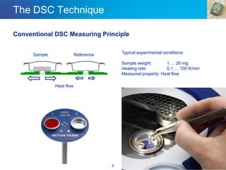
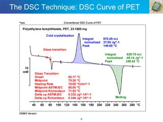
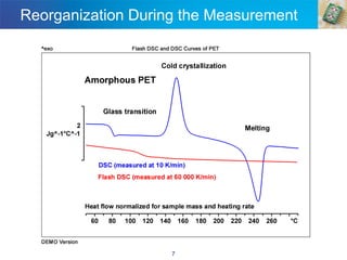
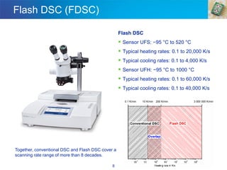

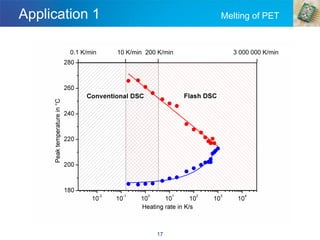
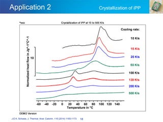
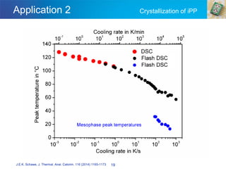
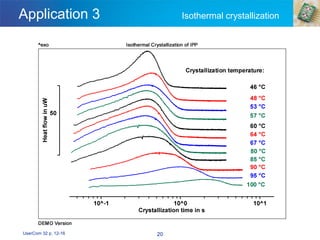
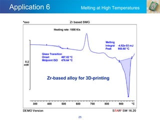
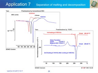
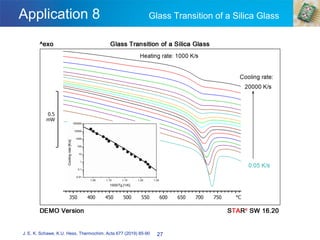


Fast scanning chip calorimetry (flash DSC) is a complementary technique to conventional differential scanning calorimetry (DSC) that allows for rapid and precise thermal analysis of materials. It offers ultra-high heating and cooling rates, enabling exploration of reorganization processes and structural formation in various materials. The flash DSC enhances manufacturing efficiency and product quality by providing critical insights into material behaviors under production conditions.