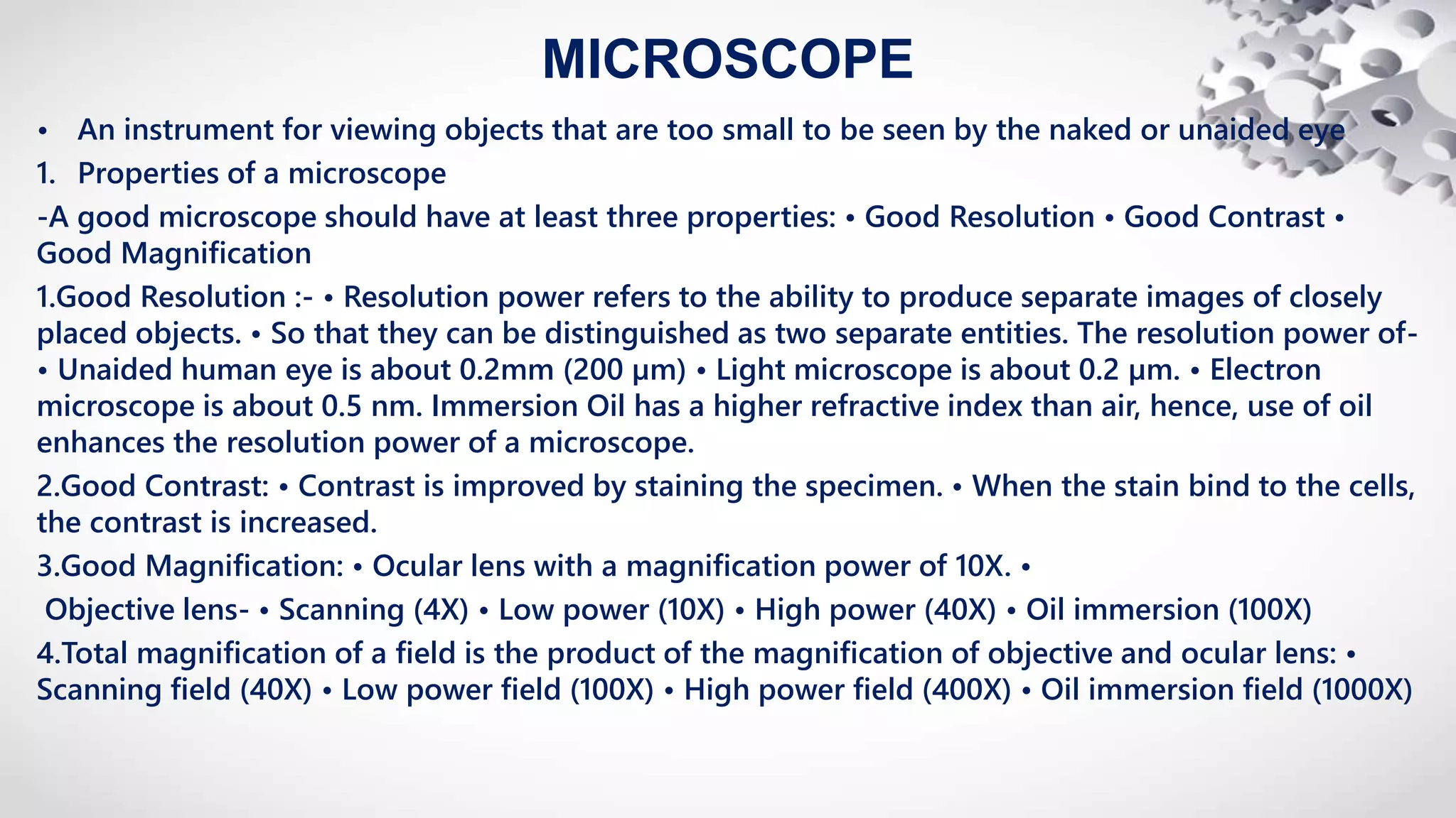
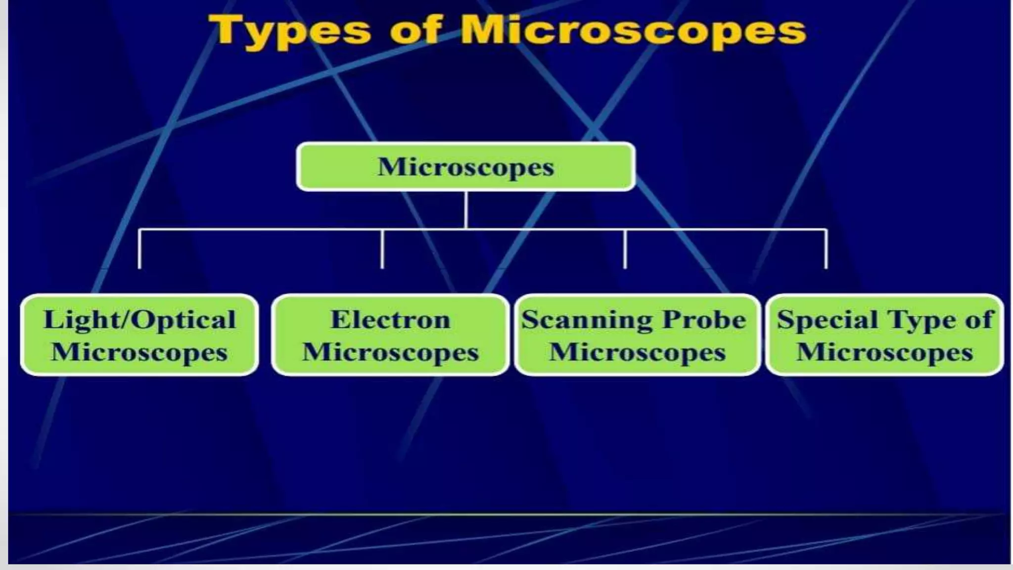
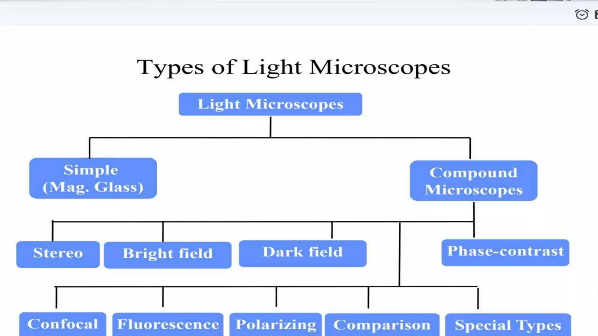
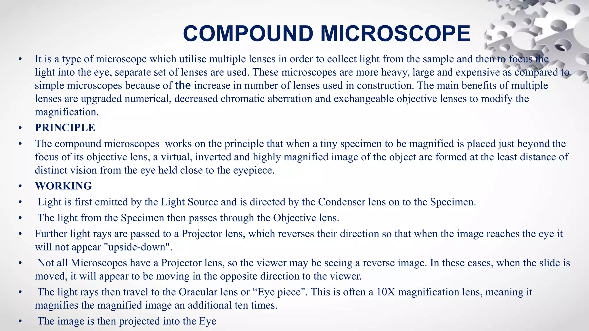
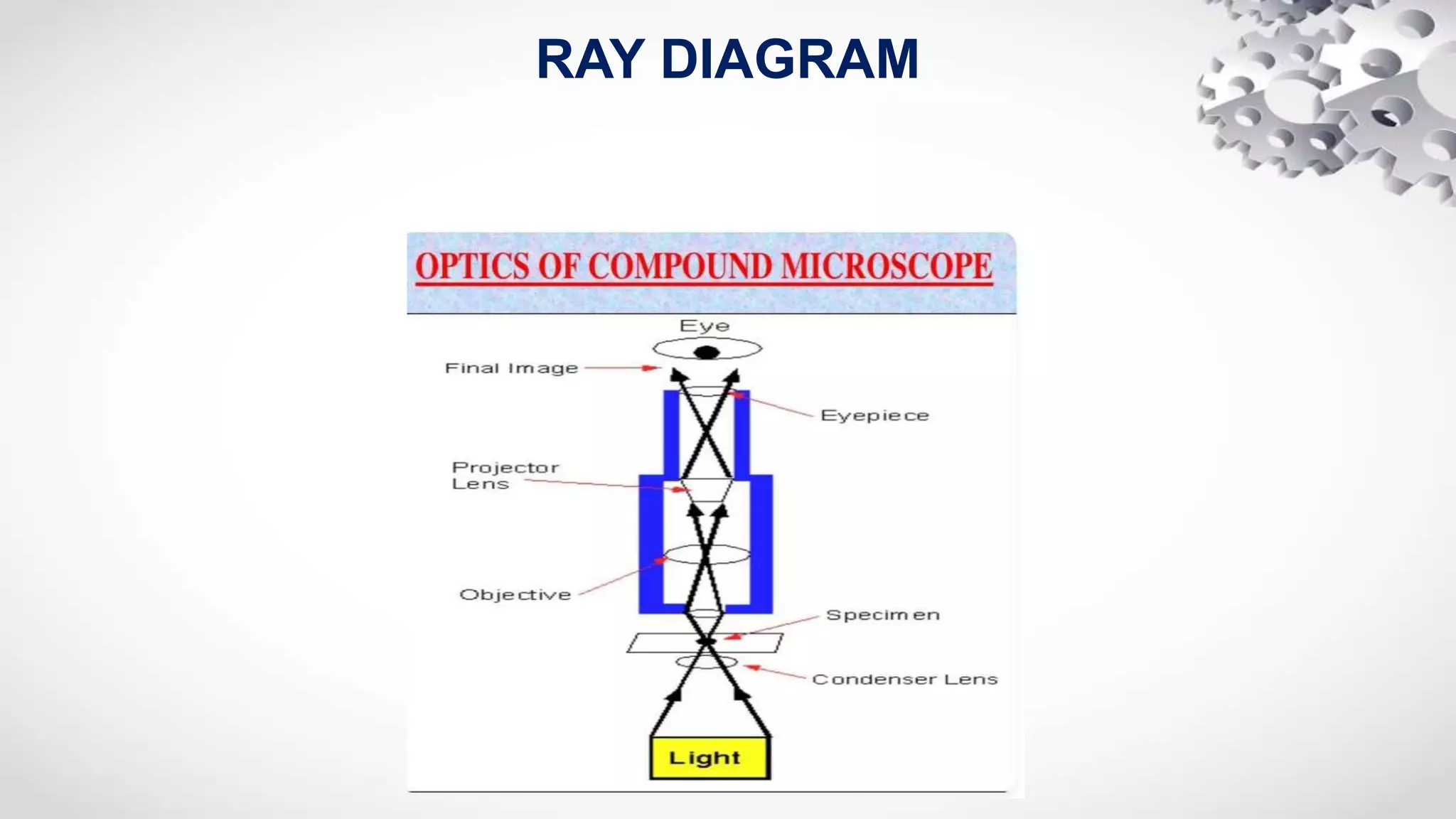
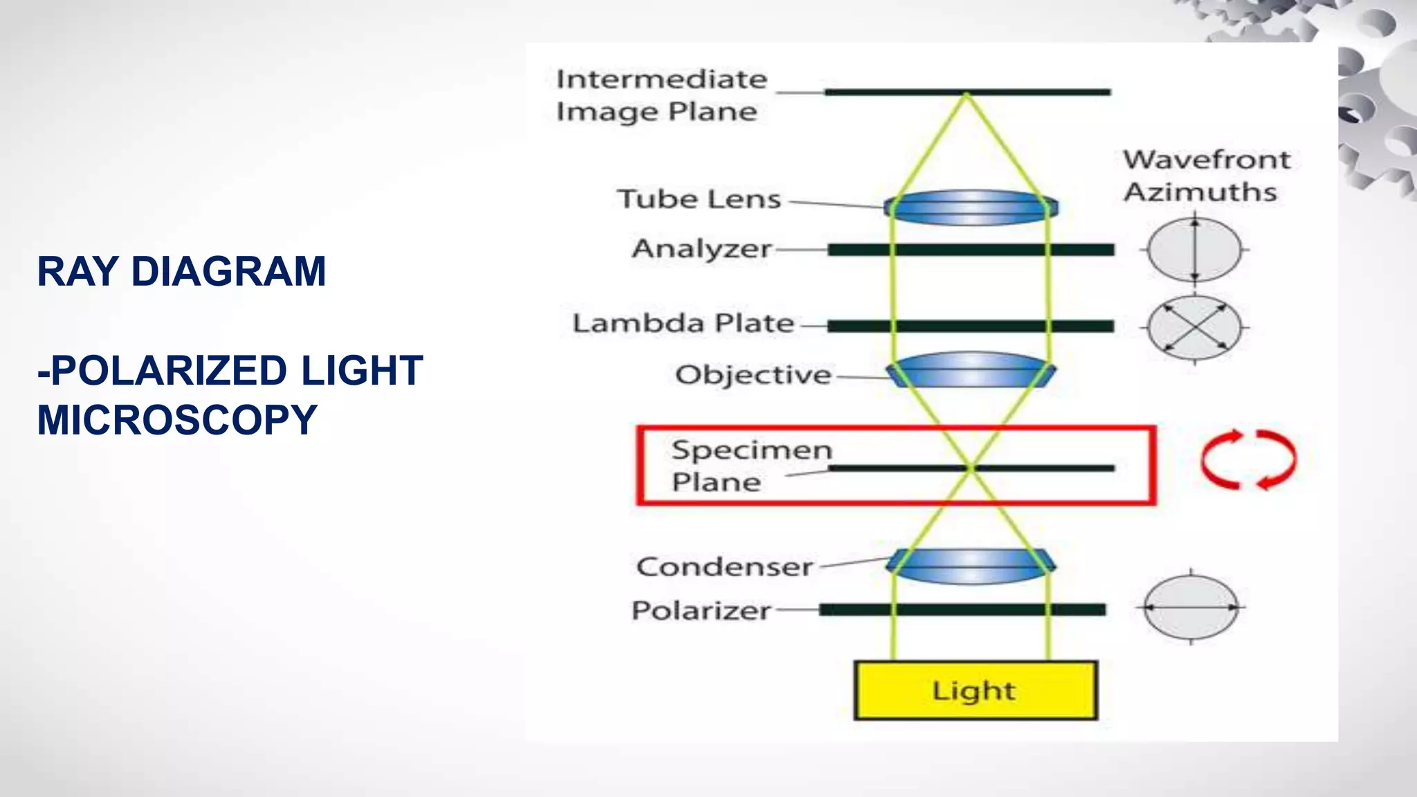
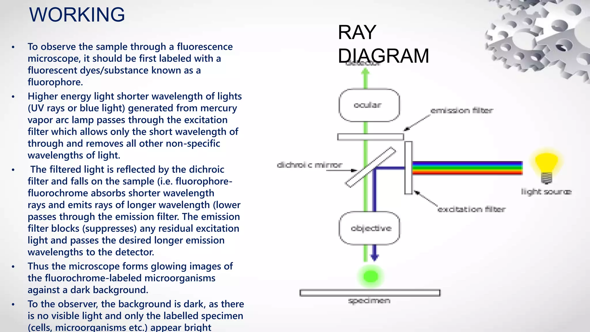
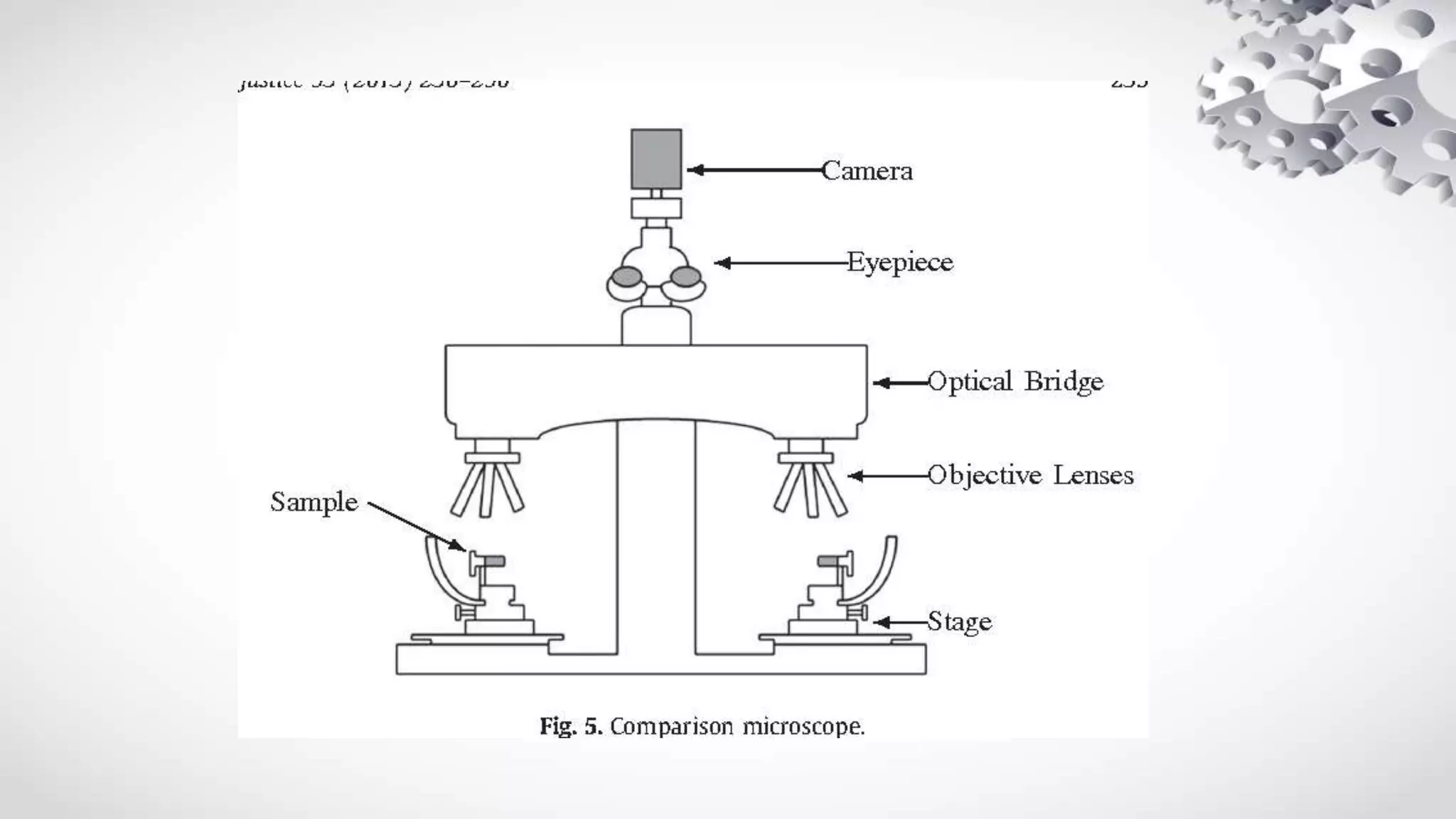
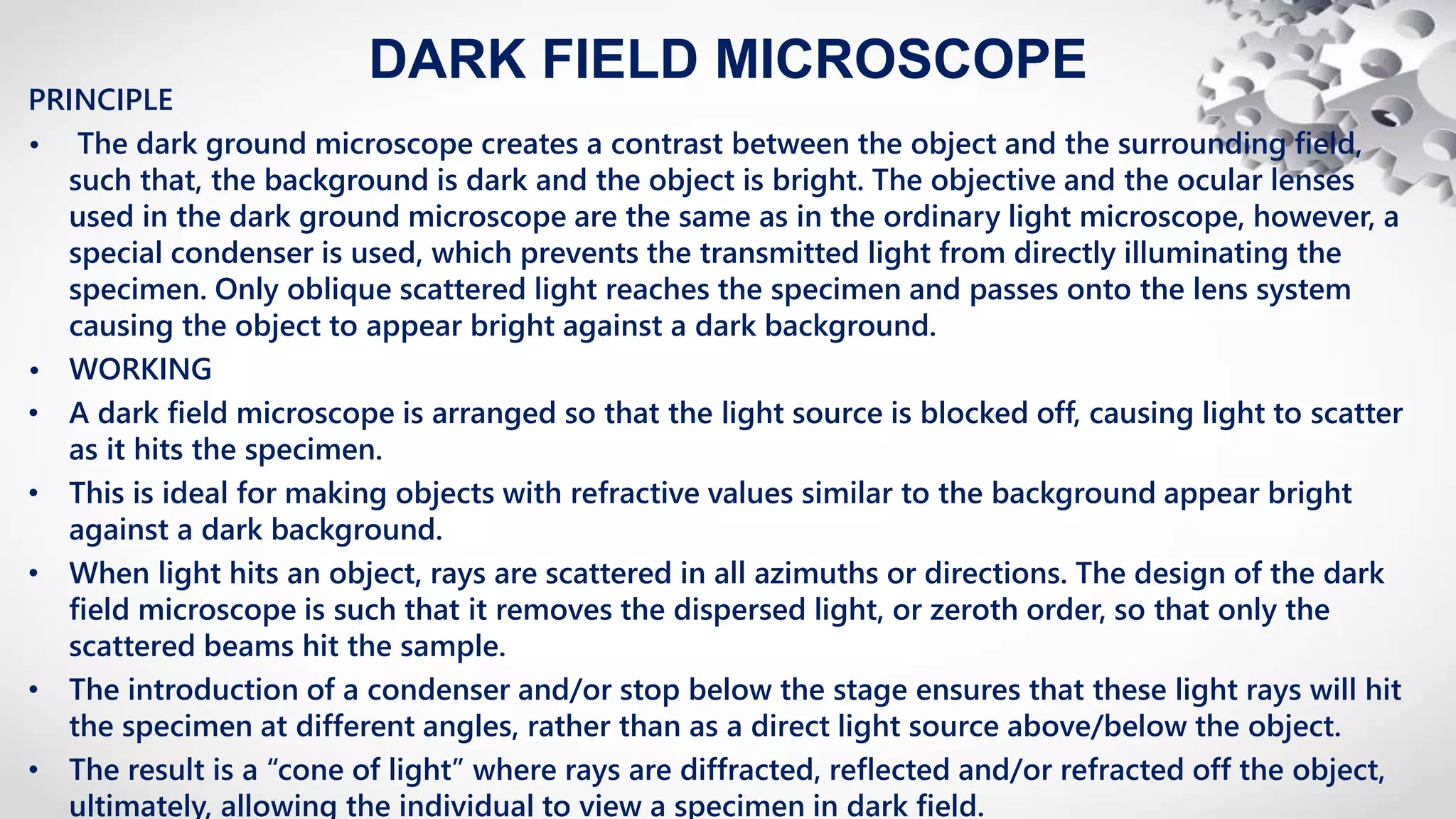
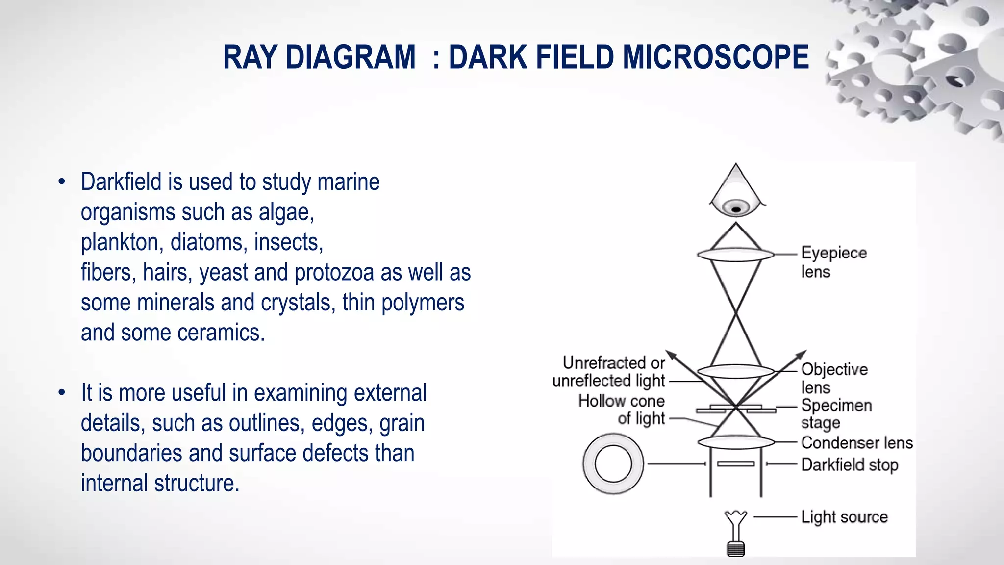
The present is on Instrumentation of various microscopes such as compound microscope, stereo microscope, polarized microscope, comparison microscope, fluorescent microscope, dark field microscope, electron microscope and it also discusses about the forensic applications of each microscope briefly.
2. UNIT 1-MICROSCOPE
Principles, ray diagrams, parts and working, sample
preparation and Forensic applications of-
1. Simple microscope
2. Compound microscope
3. Stereo microscope
4. Polarized light microscope
5. Dark-field microscope
6. Comparison microscope
7. Fluorescent microscope
8. Electron microscope
3. MICROSCOPE
• An instrument for viewing objects that are too small to be seen by the naked or unaided eye
1. Properties of a microscope
-A good microscope should have at least three properties: • Good Resolution • Good Contrast •
Good Magnification
1.Good Resolution :- • Resolution power refers to the ability to produce separate images of closely
placed objects. • So that they can be distinguished as two separate entities. The resolution power of-
• Unaided human eye is about 0.2mm (200 µm) • Light microscope is about 0.2 µm. • Electron
microscope is about 0.5 nm. Immersion Oil has a higher refractive index than air, hence, use of oil
enhances the resolution power of a microscope.
2.Good Contrast: • Contrast is improved by staining the specimen. • When the stain bind to the cells,
the contrast is increased.
3.Good Magnification: • Ocular lens with a magnification power of 10X. •
Objective lens- • Scanning (4X) • Low power (10X) • High power (40X) • Oil immersion (100X)
4.Total magnification of a field is the product of the magnification of objective and ocular lens: •
Scanning field (40X) • Low power field (100X) • High power field (400X) • Oil immersion field (1000X)
4.
5.
6. • It is a type of microscopе which utilise multiple lenses in order to collect light from the sample and then to focus the
light into the eye, separate set of lenses are used. These microscopеs are more heavy, large and expensive as compared to
simple microscopеs because of the increase in number of lenses used in construction. The main benefits of multiple
lenses are upgraded numerical, decreased chromatic aberration and exchangeable objective lenses to modify the
magnification.
• PRINCIPLE
• The compound microscopes works on the principle that when a tiny specimen to be magnified is placed just beyond the
focus of its objective lens, a virtual, inverted and highly magnified image of the object are formed at the least distance of
distinct vision from the eye held close to the eyepiece.
• WORKING
• Light is first emitted by the Light Source and is directed by the Condenser lens on to the Specimen.
• The light from the Specimen then passes through the Objective lens.
• Further light rays are passed to a Projector lens, which reverses their direction so that when the image reaches the eye it
will not appear "upside-down".
• Not all Microscopes have a Projector lens, so the viewer may be seeing a reverse image. In these cases, when the slide is
moved, it will appear to be moving in the opposite direction to the viewer.
• The light rays then travel to the Oracular lens or “Eye piece". This is often a 10X magnification lens, meaning it
magnifies the magnified image an additional ten times.
• The image is then projected into the Eye
COMPOUND MICROSCOPE
7. 1. Eye piece And Body Tube. •Eyepiece is the lens through which the viewer looks to see the specimen.
It is usually contains a 10X or 15X power lens. The Body Tube connects the eyepiece to the objective
lenses.
2. Objectives And Stage Clips. •Objective Lenses are the one of the most important part of a
Compound Microscope. They are the closet to the specimen. A standard Microscope has three to
four Objective Lenses which range from 4X to 100X. •Stage Clips are metal clips that held the slide in
a place.
3. Arm And Base. •The Arm connects the Body Tube to the base of the Microscope. •The Base supports
the Microscope and its where Illuminator.
4. Illuminator And Stage. •Illuminator is the light source for a Microscope. A Compound Light
Microscope uses a low voltage bulb as an Illuminator. •Stage is the flat platform where the slide is
placed.
5. Nosepiece And Aperture. •Nosepiece is a rotating turret that holds the Objective lenses. The viewer
spins the Nosepiece to select different Objective lenses.
6. The Aperture is the middle of the stage that allows light from the Illuminator to reach the specimen.
7. Condenser And Diaphragm. •A Condenser gathers and focuses light from the Illuminator onto the
specimen being viewed. •Diaphragm is a five holed disk placed under the stage. Each hole is of a
different diameter. By turning it, you can vary the amount of light passing through the stage
opening.
PARTS: Eye piece, Body Tube ,Arm Stage, Course adjustment knob ,Fine
adjustment knob , Base ,Nosepiece, Objective lenses, Stage Clips, Diaphragm,
Illuminator
9. STEREO MICROSCOPE
• A stereo microscope is an optical microscope that provides a three-dimensional view of a specimen. It is
also known by other names such as dissecting microscope and stereo zoom microscope. Dissecting
microscope parts include separate objective lenses and eyepieces. As a result, you have two separate
optical paths for each eye. The slightly different angling views to the left and right eyes produce a three-
dimensional visual. Because it gives the three-dimensional view it is also called as the dissecting
microscope.
• PRINCIPLE
• A stereo or a dissecting microscope uses reflected light from the object. It magnifies at a low power hence
ideal for amplifying opaque objects. Since it uses light that naturally reflects from the specimen, it is
helpful to examine solid or thick samples. The magnification of a stereo microscope ranges between 10x
and 50x.
• WORKING
• The principle of stereo microscope depends on the 2 different paths of light from objective lens and the
eyepiece. Both these lights provides a different angle of viewing in which the bottom light is used for
viewing the samples while the top light is used during dissecting.
• The two eyepieces enables in this microscope enables a comforting view of the sample from different
angles simultaneously.
• It also consists of a digital camera that is used for viewing the images of the samples in the computer for a
close observation. The image produced is a little larger than normal and is recorded.
• The dissecting microscope has two magnifications known as Fixed magnification and Zoom magnification.
11. POLARIZED LIGHT MICROSCOPE
• Polarized Light
• Light is an electromagnetic wave. Although light waves can vibrate in all directions, in general, they are described as vibrating
in two directions at right angles to each other. Any light which vibrates in more than one direction is called ‘unpolarised light’;
whereas, a light wave that vibrates in a single direction is called ‘polarised light’. The human eye is not sensitive to the direction
of vibration of light.
• Converting Non-Polarised to Polarized Light
• Polarized light microscopes work by converting unpolarized light to polarized light. One way in which this can be achieved is by
absorption of light vibrational movement in one specific direction. This can be done by certain natural minerals, including
tourmaline, or by synthetic films that perform the same function.
• Polaroid filters consist of tiny crystallites of iodoquinine sulfate which are oriented in the same direction and embedded in a
polymeric filter. This embedding is done to prevent migration and change in the orientation of the crystals. The device which
selects the plane-polarized from natural or unpolarized light is called a polarizer.
• PRINCIPLE
• In a polarized light microscope, a polarizer intervenes between the light source and the sample. Thus, the polarized light source
is converted into plane-polarized light before it hits the sample
• PARTS
• Polarizers
• Polarizing filters are the most critical part of the polarized light microscope. There are usually two polarizing filters: the polarizer
and the analyzer. The polarizer is located below the specimen stage and can be rotated through 360°. It helps to polarize the
light which falls on the specimen.The analyzer is placed above the objective and may be rotatable in some cases. It combines
the different rays emerging from the specimen to generate the final image.
12. • Specialized Stage
• This is the specimen stage and it can rotate 360° to facilitate the correct orientation of the specimen with the objective
plane. In several stages, a Vernier scale is also provided to provide an accuracy of 0.1° in the rotational angle of the stage.
• Strain-Free Objectives
• Any stress on the objective during installation can lead to a change in the optical properties of the lens which can reduce
the performance.Strain can also be introduced if the lens is mounted too tightly on the frame. Also, anti-reflection coatings
and refractive properties must be accurately assessed in order to ensure polarization and increased contrast.
• Revolving Nosepiece
• As the stage and objectives can revolve in many polarizing microscopes, a revolving nosepiece is also often fitted such that
the specimen can be visualized in the center of the view field even if the stage is rotated. Compensator and Retardation
Plates. Several polarization microscopes have compensators and/or retardation plates. This is placed between the crossed
polarizers to increase the difference in the optical path in the specimen. This would further increase the contrast of the
image quality.Thus, polarizing microscopes are being used to increase the image contrast to visualize many anisotropic sub-
cellular structures.
• WORKING
• In a polarized light microscope, a polarizer intervenes between the light source and the sample. Thus, the polarized light
source is converted into plane-polarized light before it hits the sample. This polarized light falls on a doubly refracting
specimen which generates two wave components that are at right angles to each other. These two waves are called
ordinary and extraordinary light rays.
• The waves pass through the specimen in different phases. They are then combined using constructive and destructive
interference, by an analyzer. This leads to the final generation of a high-contrast image.
• FORENSIC APPLICATION
• Hair Sample: Natural Light Hair Sample: Polarized Light This can provide information about the shape, color, and size of
minerals and it is used to identify hair, human-made fibers and paint.
14. FLOURESCENCE MICROSCOPE
• PRINCIPLE
• Fluorescence microscopy is a type of light microscope that works on the principle of
fluorescence. A substance is said to be fluorescent when it absorbs the energy of invisible
shorter wavelength radiation (such as UV light 100-400nm) and emits longer wavelength
radiation of visible light (such as green or red light-400nm-800nm)
• PARTS
• Fluorescence microscopes as other light microscope has a
• Light source: Xenon arc lamp or mercury-vapor lamp are common; power LED and lasers are
used in more advanced forms.
• A set of optical filters: Optical filters include a set of a compatible excitation filter, emission
filter, and dichroic beam splitter;
• An excitation filter selects the wavelengths to excite a particular dye within the specimen.
• A dichroic beam splitter/ dichroic mirror reflects light in the excitation band and transmit light
in the emission band, enabling the classic epifluorescence incident light illumination.
• An emission filter serves as a kind of quality control by letting only the wavelengths of interest
emitted by the fluorophore pass through.
• Darkfield condenser: It provides a black background against which the fluorescent objects
15. WORKING
• To observe the sample through a fluorescence
microscope, it should be first labeled with a
fluorescent dyes/substance known as a
fluorophore.
• Higher energy light shorter wavelength of lights
(UV rays or blue light) generated from mercury
vapor arc lamp passes through the excitation
filter which allows only the short wavelength of
through and removes all other non-specific
wavelengths of light.
• The filtered light is reflected by the dichroic
filter and falls on the sample (i.e. fluorophore-
fluorochrome absorbs shorter wavelength
rays and emits rays of longer wavelength (lower
passes through the emission filter. The emission
filter blocks (suppresses) any residual excitation
light and passes the desired longer emission
wavelengths to the detector.
• Thus the microscope forms glowing images of
the fluorochrome-labeled microorganisms
against a dark background.
• To the observer, the background is dark, as there
is no visible light and only the labelled specimen
(cells, microorganisms etc.) appear bright
RAY
DIAGRAM
16. COMPARISON MICROSCOPE
• PRINCIPLE
• A comparison microscopе is a tool used to examine simultaneous specimens. It comprises of
two microscopеs linked by an optical bridge, which results in a split view window allowing
two separate objects to be viewed consecutively. This prevents the viewer having to depend
on memory when associating two objects under a conventional microscopе. The modern
apparatus has various optical, mechanical and electronic refinements, including fiber optic
illumination, video capabilities, digital imaging, automatic exposure for conventional
photography, etc.
• The comparison microscope is a key tool for firearm and toolmark examination.
• WORKING
• Comparison Microscope Provides a side by side comparison of specimens Structure consists
of 2 compound microscopes combined into one unit.
• Designed to use a bridge incorporating a series of mirrors and lenses to join 2 independent
objective lenses into a singular binocular unit.
• Viewer will see a circular field divided into 2 equal parts by a thin line.
• The specimen on the left will be seen in the left half of the field of view and the specimen on
the right will be seen in the right half of the field of view.
17.
18. DARK FIELD MICROSCOPE
PRINCIPLE
• The dark ground microscope creates a contrast between the object and the surrounding field,
such that, the background is dark and the object is bright. The objective and the ocular lenses
used in the dark ground microscope are the same as in the ordinary light microscope, however, a
special condenser is used, which prevents the transmitted light from directly illuminating the
specimen. Only oblique scattered light reaches the specimen and passes onto the lens system
causing the object to appear bright against a dark background.
• WORKING
• A dark field microscope is arranged so that the light source is blocked off, causing light to scatter
as it hits the specimen.
• This is ideal for making objects with refractive values similar to the background appear bright
against a dark background.
• When light hits an object, rays are scattered in all azimuths or directions. The design of the dark
field microscope is such that it removes the dispersed light, or zeroth order, so that only the
scattered beams hit the sample.
• The introduction of a condenser and/or stop below the stage ensures that these light rays will hit
the specimen at different angles, rather than as a direct light source above/below the object.
• The result is a “cone of light” where rays are diffracted, reflected and/or refracted off the object,
ultimately, allowing the individual to view a specimen in dark field.
19. RAY DIAGRAM : DARK FIELD MICROSCOPE
• Darkfield is used to study marine
organisms such as algae,
plankton, diatoms, insects,
fibers, hairs, yeast and protozoa as well as
some minerals and crystals, thin polymers
and some ceramics.
• It is more useful in examining external
details, such as outlines, edges, grain
boundaries and surface defects than
internal structure.
20. ELECTRON MICROSCOPE
• An electron microscope uses an ‘electron beam’ to produce the image of the object and magnification is
obtained by ‘electromagnetic fields’; unlike light or optical microscopes, in which ‘light waves’ are used to
produce the image and magnification is obtained by a system of ‘optical lenses’.
• That is why, despite its smaller numerical aperture, an electron microscope can resolve objects as small as
0.001µ (=10 Å), as compared to 0.2µ by a light microscope. Thus, the resolving power of an electron
microscope is 200 times greater than that of a light microscope. It produces useful magnification up to X
400,000, as compared to X 2000 in a light microscope. Thus, the useful magnification is 200 times greater
in an electron microscope than that in a light microscope.
• PRINCIPLE
• The electron microscope uses an electron beam to create an image, with electromagnets acting as lenses.
The limit of resolution is improved by a factor of 1000 over the light microscope.
• Transmission Electron Microscopy is particularly meant to study thin specimen which allows the incident
electrons to traverse through after due interactions. The Transmission Electron Microscope (TEM)
produces a two-dimensional (2D) image of an ultra-thin section by capturing electrons that have passed
through the specimen. The degree of interaction between the electrons and the heavy metal stain
influence the kinetic energy of the electrons, which are collected by a fluorescent plate. The light of
fluctuating intensity produced is directly proportional to the electron's kinetic energy and is used to
produce the image. The Transmission Electron Microscope is useful for studying a cell's interior and its
ultra-structure.
• A Scanning Electron Microscope (SEM) used to make a three-dimensional image of the specimen surface.
SEM requires low kinetic energy electrons which need not penetrate deep inside the sample, instead
21. WORKING:
• Electrons accelerated to a particular potential possess the same wavelength which constitutes a more or less
monochromatic beam. The beam of high energy electrons interacts with the specimen within a certain area
of cross section depending upon the electron beam energy. An accelerated electron penetrates into the
electron cloud of an atom and its path is deflected causing it to scatter at an angle. In some cases, even
complete backscattering can occur generating the back-scattered electrons (BSE).
• Electron microscope utilizes all such interactions occurring between the matter and the highly accelerated
electron incident on it. These transmitted electrons are focused with the help of electromagnetic lenses and
their very short wavelength allows the specimen to be imaged with a very high spatial resolution as
compared to the light microscope. Highly accelerated electrons are able to transmit through a thin specimen
and are used for the formation of image in Transmission Electron Microscopy.
• These electrons can transmitted unscattered through the specimen, else can be scattered elastically or
inelastically. In elastic scattering, the incident electrons are deflected from their original path and scattered
by atoms in the specimen in an elastic fashion without any loss of energy. Such electron leave the sample
with almost same kinetic energy and velocity as was possessed by it initially. However, the trajectory of
electron may change after interaction with the specimen. An inelastic interaction involves transfer of energy
from the incident electrons to the sample so that the energy of the electron after interaction with the sample
is reduced.
• These scattered electrons are then transmitted through the remaining portions of the specimen and can be
analogize by using magnetic lenses to form a configuration of spots; each spot corresponding to a specific
atomic spacing. This pattern can then yield information about the orientation, atomic arrangements and
phases present in the area being examined.
22.
23. FORENSIC APPLICATIONS
• Microscopic examinations and analysis of evidences provide
valuable results in crime scene investigation. Some of them are:
• Gunshot residue analysis
• Firearms identification – bullet marking comparison
• Investigation of gemstones and jewellery
• Examination of paint particles and fibers
• Filament bulb investigation at traffic signals
• Handwriting and print examination/forgery
• Counterfeit bank notes
• Trace comparison
• Examination of non-conducting materials