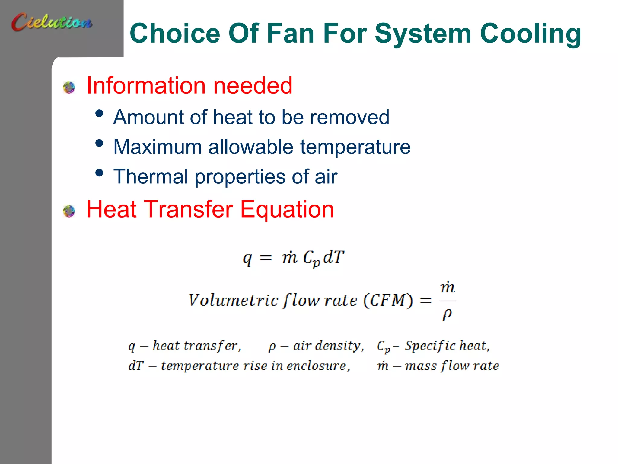
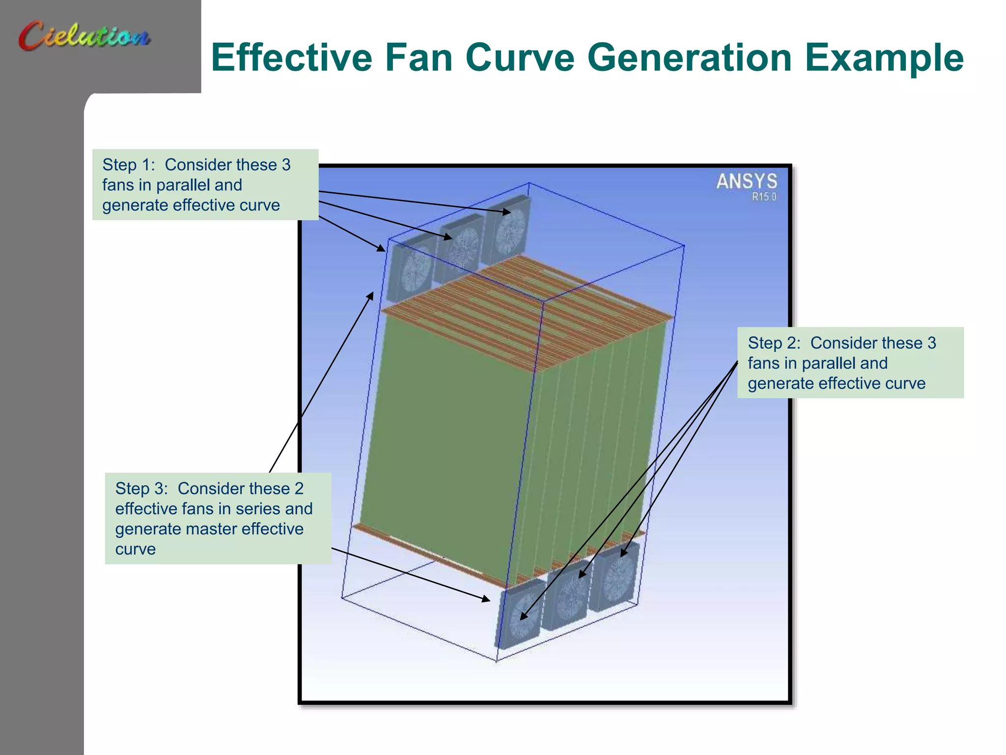
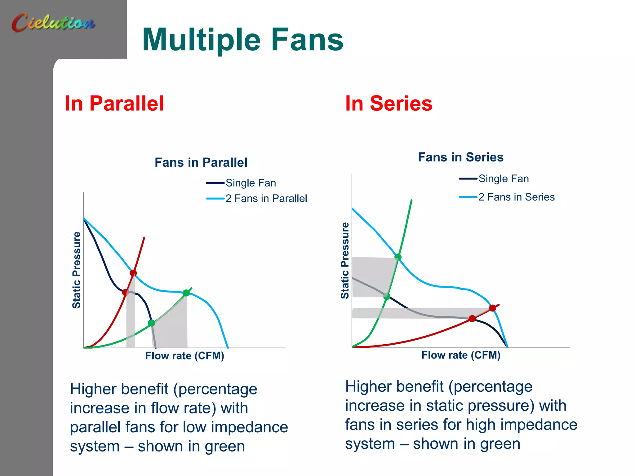
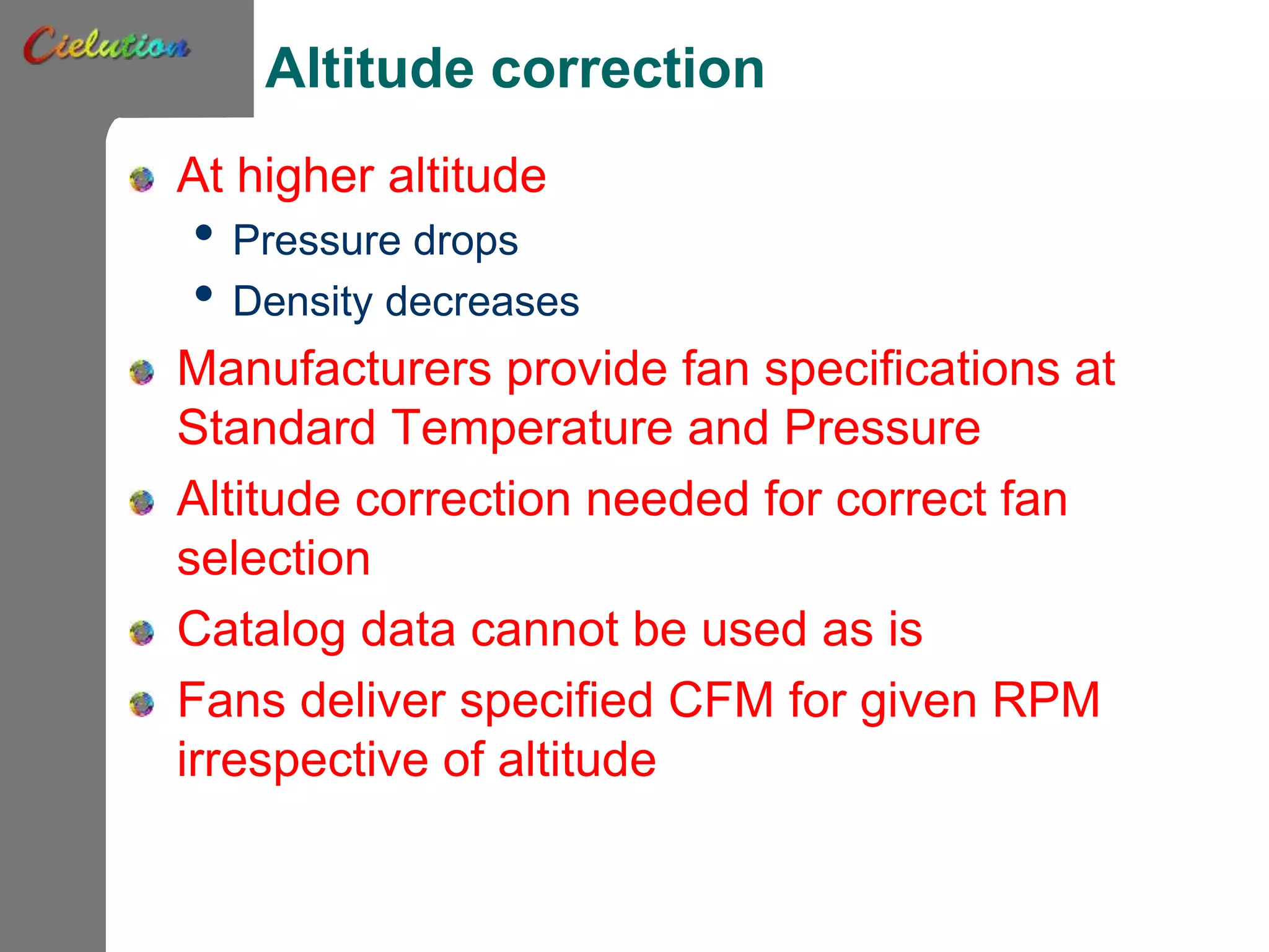
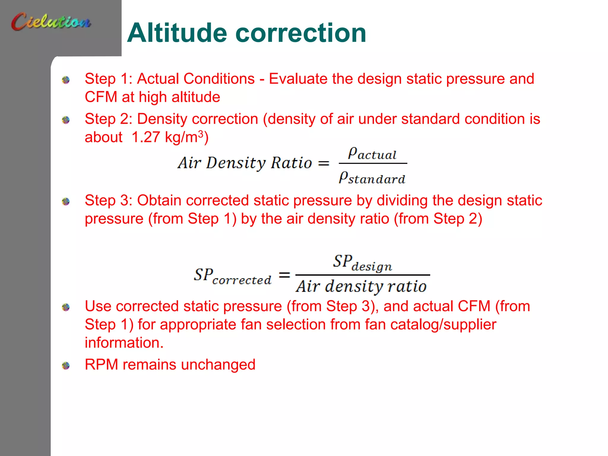
Arunima Panigrahy
Technical Note:
Some Useful Fan Rules for
Electronics Cooling
Common Modes Of Cooling
Electronic Components
Air cooling
• Natural convection passive cooling
• Forced convection
Liquid cooling
This technical note applies to air cooling with
forced convection.
Air Cooling
Most popular mode for cooling electronics
Design requirement based on need of high flow
rate or high pressure drops
Cooling capacity increased by use of multiple
fans
Fans in series vs. parallel
Altitude correction
Choice Of Fan For System Cooling
Information needed
• Amount of heat to be removed
• Maximum allowable temperature
• Thermal properties of air
Heat Transfer Equation
Basic Fan Laws
Choice of fan will further depend on the Fan Laws.
Law of Physics for motion can be expressed as
Hence the pressure required is proportional to the
square of velocity of air, or static pressure
Also,
Fan Characteristic curve
0
0.02
0.04
0.06
0.08
0.1
0.12
0 5 10 15 20 25
StaticPressure(inH2O)
Flow Rate (CFM)
Typical Axial Fan Curve
12.0 V
13.2 V
9.6 V
System Impedance Vs. fan Curve
StaticPressure
Flow Rate
Note: Effective fan curve for determining fan operating point is determined
from all the fans in the system. We’ll show how in the next slides.
System impedance curves
Multiple Fans
In Parallel (Example: Fans
in a single fan tray)
In Series (Example intake and
exhaust fans in a system)
StaticPressure(inchofH2O
Flow rate (CFM)
Single Fan
2 Fans in
Parallel
StaticPressure(inchofH2O
Flow rate (CFM)
Single Fan
2 Fans in
Series
•For each pressure drop in the fan
curve table, add corresponding flow
rates of each fan in parallel (i.e. on
the same tray)
•For each flow rate in the fan curve
table, add corresponding pressure
drops of each fan in parallel
Effective Fan Curve Generation Example
Step 1: Consider these 3
fans in parallel and
generate effective curve
Step 2: Consider these 3
fans in parallel and
generate effective curve
Step 3: Consider these 2
effective fans in series and
generate master effective
curve
Multiple Fans
In Parallel In Series
StaticPressure
Flow rate (CFM)
Fans in Parallel
Single Fan
2 Fans in Parallel
Higher benefit (percentage
increase in flow rate) with
parallel fans for low impedance
system – shown in green
StaticPressure
Flow rate (CFM)
Fans in Series
Single Fan
2 Fans in Series
Higher benefit (percentage
increase in static pressure) with
fans in series for high impedance
system – shown in green
Altitude correction
At higher altitude
• Pressure drops
• Density decreases
Manufacturers provide fan specifications at
Standard Temperature and Pressure
Altitude correction needed for correct fan
selection
Catalog data cannot be used as is
Fans deliver specified CFM for given RPM
irrespective of altitude
Altitude correction
Step 1: Actual Conditions - Evaluate the design static pressure and
CFM at high altitude
Step 2: Density correction (density of air under standard condition is
about 1.27 kg/m3)
Step 3: Obtain corrected static pressure by dividing the design static
pressure (from Step 1) by the air density ratio (from Step 2)
Use corrected static pressure (from Step 3), and actual CFM (from
Step 1) for appropriate fan selection from fan catalog/supplier
information.
RPM remains unchanged
Summary
Considerations in air moving strategy
• Amount of heat dissipated
• Maximum temperature of the enclosure
• Required flow rate, pressure drop
• Fan trays
o Parallel?
o Series?
o In most large systems this is a combination of both
• Impact of altitude on choice of fan

Fan choice ap-v3

  • 1.
    Arunima Panigrahy Technical Note: SomeUseful Fan Rules for Electronics Cooling
  • 2.
    Common Modes OfCooling Electronic Components Air cooling • Natural convection passive cooling • Forced convection Liquid cooling This technical note applies to air cooling with forced convection.
  • 3.
    Air Cooling Most popularmode for cooling electronics Design requirement based on need of high flow rate or high pressure drops Cooling capacity increased by use of multiple fans Fans in series vs. parallel Altitude correction
  • 4.
    Choice Of FanFor System Cooling Information needed • Amount of heat to be removed • Maximum allowable temperature • Thermal properties of air Heat Transfer Equation
  • 5.
    Basic Fan Laws Choiceof fan will further depend on the Fan Laws. Law of Physics for motion can be expressed as Hence the pressure required is proportional to the square of velocity of air, or static pressure Also,
  • 6.
    Fan Characteristic curve 0 0.02 0.04 0.06 0.08 0.1 0.12 05 10 15 20 25 StaticPressure(inH2O) Flow Rate (CFM) Typical Axial Fan Curve 12.0 V 13.2 V 9.6 V
  • 7.
    System Impedance Vs.fan Curve StaticPressure Flow Rate Note: Effective fan curve for determining fan operating point is determined from all the fans in the system. We’ll show how in the next slides. System impedance curves
  • 8.
    Multiple Fans In Parallel(Example: Fans in a single fan tray) In Series (Example intake and exhaust fans in a system) StaticPressure(inchofH2O Flow rate (CFM) Single Fan 2 Fans in Parallel StaticPressure(inchofH2O Flow rate (CFM) Single Fan 2 Fans in Series •For each pressure drop in the fan curve table, add corresponding flow rates of each fan in parallel (i.e. on the same tray) •For each flow rate in the fan curve table, add corresponding pressure drops of each fan in parallel
  • 9.
    Effective Fan CurveGeneration Example Step 1: Consider these 3 fans in parallel and generate effective curve Step 2: Consider these 3 fans in parallel and generate effective curve Step 3: Consider these 2 effective fans in series and generate master effective curve
  • 10.
    Multiple Fans In ParallelIn Series StaticPressure Flow rate (CFM) Fans in Parallel Single Fan 2 Fans in Parallel Higher benefit (percentage increase in flow rate) with parallel fans for low impedance system – shown in green StaticPressure Flow rate (CFM) Fans in Series Single Fan 2 Fans in Series Higher benefit (percentage increase in static pressure) with fans in series for high impedance system – shown in green
  • 11.
    Altitude correction At higheraltitude • Pressure drops • Density decreases Manufacturers provide fan specifications at Standard Temperature and Pressure Altitude correction needed for correct fan selection Catalog data cannot be used as is Fans deliver specified CFM for given RPM irrespective of altitude
  • 12.
    Altitude correction Step 1:Actual Conditions - Evaluate the design static pressure and CFM at high altitude Step 2: Density correction (density of air under standard condition is about 1.27 kg/m3) Step 3: Obtain corrected static pressure by dividing the design static pressure (from Step 1) by the air density ratio (from Step 2) Use corrected static pressure (from Step 3), and actual CFM (from Step 1) for appropriate fan selection from fan catalog/supplier information. RPM remains unchanged
  • 13.
    Summary Considerations in airmoving strategy • Amount of heat dissipated • Maximum temperature of the enclosure • Required flow rate, pressure drop • Fan trays o Parallel? o Series? o In most large systems this is a combination of both • Impact of altitude on choice of fan