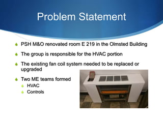
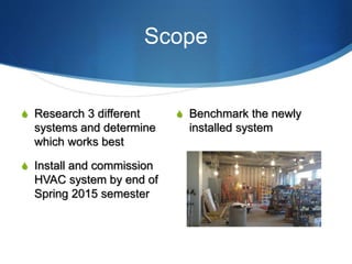
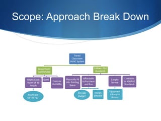
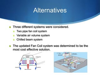
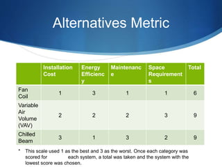
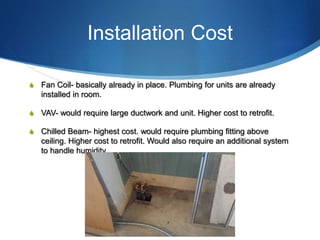
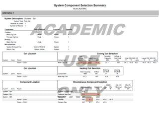
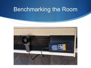
S
Siemens Room
Renovation
HVAC System
Donald Morgan
Nick Hunt
Steven Kinney
David Amrhein
Problem Statement
S PSH M&O renovated room E 219 in the Olmsted Building
S The group is responsible for the HVAC portion
S The existing fan coil system needed to be replaced or
upgraded
S Two ME teams formed
S HVAC
S Controls
Teams Involved
S ME Teams – analyzing old and new system and choosing
a suitable control system.
S EE – 2 teams choosing wiring and lighting systems for
the room.
Scope
S Research 3 different
systems and determine
which works best
S Install and commission
HVAC system by end of
Spring 2015 semester
S Benchmark the newly
installed system
Scope: Approach Break Down
Alternatives
S Three different systems were considered.
S Two pipe fan coil system
S Variable air volume system
S Chilled beam system
S The updated Fan Coil system was determined to be the
most cost effective solution.
Alternatives Metric
Installation
Cost
Energy
Efficienc
y
Maintenanc
e
Space
Requirement
s
Total
Fan
Coil
1 3 1 1 6
Variable
Air
Volume
(VAV)
2 2 2 3 9
Chilled
Beam
3 1 3 2 9
* This scale used 1 as the best and 3 as the worst. Once each category was
scored for each system, a total was taken and the system with the
lowest score was chosen.
Installation Cost
S Fan Coil- basically already in place. Plumbing for units are already
installed in room.
S VAV- would require large ductwork and unit. Higher cost to retrofit.
S Chilled Beam- highest cost. would require plumbing fitting above
ceiling. Higher cost to retrofit. Would also require an additional system
to handle humidity.
Energy Efficiency
S Fan Coil- least efficient units to run. They rely the most on electricity to
circulate air.
S VAV- most efficient system. Keeps air at constant temperature and
varies fan speed to regulate temperature.
S Chilled Beam- requires fans to circulate heated air around room during
winter.
Maintenance
S Fan Coil- easiest and safest to maintain. Conveniently accessible
filters, located on ground level along walls.
S VAV- located above ceilings, reaching filters requires ladders,
increased fall risk, working above-head.
S Chilled Beam- requires working at ceiling level on ladder, increased
fall risk, most cleaning required.
Space Requirements
S Fan Coil- least amount of space required, retrofits very easily. No
above-ceiling additional ductwork or equipment required.
S VAV- requires the most above ceiling ductwork and equipment. Making
everything easily accessible would be difficult.
S Chilled Beam- would require additional plumbing as well as chilled
beams installed in ceiling. (42 ft of beams necessary to effectively cool
room)
Final Choice: Fan Coil Units
S FCBB0601C**ABH10AC3M00—
01x00H30000000000000
S B: Cabinet type: Vertical
S 060: Unit Size: 510 cfm; 48.02 MBh
S C: Coil: 4 Row Hot Water
Manual Calculations
S ASHRAE 62.1 Ventilation Standards
S Vbz = RpPz+RaAz
S =(7.5*60)+(.06*1075)=514.5 cfm
S 12” x 5.5” Duct will deliver 260 cfm of
airflow to the room.
Energy Calculations
S Energy Savings:
S Lighting Controls: electricity reduction of 10%
S => 795 Btu/h = 1.45 million btu/year = cost saving of $56
S Temperature Controls: Temperature drift from 68°F to 72°F
S => 510.3 Btu/h = .93 million btu/year = cost saving of $36
S Total: If implemented for 10hr/day around $93 per room
can be saved over the warmest part of the year.
Benchmarking the Room
Benchmark Criteria
S Ceiling Diffusers
S Right Side - 240 cfm
S Front Wall – 530 cfm
S Left Side – 230 cfm
S Fan Coil Units
S High – 780
S Medium - 575 cfm
S Low – 435 cfm
S Lighting – 86.7°F
Revit Drawing of Olmsted
219E
Questions?

Hvac presentation

  • 1.
    S Siemens Room Renovation HVAC System DonaldMorgan Nick Hunt Steven Kinney David Amrhein
  • 2.
    Problem Statement S PSHM&O renovated room E 219 in the Olmsted Building S The group is responsible for the HVAC portion S The existing fan coil system needed to be replaced or upgraded S Two ME teams formed S HVAC S Controls
  • 3.
    Teams Involved S METeams – analyzing old and new system and choosing a suitable control system. S EE – 2 teams choosing wiring and lighting systems for the room.
  • 4.
    Scope S Research 3different systems and determine which works best S Install and commission HVAC system by end of Spring 2015 semester S Benchmark the newly installed system
  • 5.
  • 6.
    Alternatives S Three differentsystems were considered. S Two pipe fan coil system S Variable air volume system S Chilled beam system S The updated Fan Coil system was determined to be the most cost effective solution.
  • 7.
    Alternatives Metric Installation Cost Energy Efficienc y Maintenanc e Space Requirement s Total Fan Coil 1 31 1 6 Variable Air Volume (VAV) 2 2 2 3 9 Chilled Beam 3 1 3 2 9 * This scale used 1 as the best and 3 as the worst. Once each category was scored for each system, a total was taken and the system with the lowest score was chosen.
  • 8.
    Installation Cost S FanCoil- basically already in place. Plumbing for units are already installed in room. S VAV- would require large ductwork and unit. Higher cost to retrofit. S Chilled Beam- highest cost. would require plumbing fitting above ceiling. Higher cost to retrofit. Would also require an additional system to handle humidity.
  • 9.
    Energy Efficiency S FanCoil- least efficient units to run. They rely the most on electricity to circulate air. S VAV- most efficient system. Keeps air at constant temperature and varies fan speed to regulate temperature. S Chilled Beam- requires fans to circulate heated air around room during winter.
  • 10.
    Maintenance S Fan Coil-easiest and safest to maintain. Conveniently accessible filters, located on ground level along walls. S VAV- located above ceilings, reaching filters requires ladders, increased fall risk, working above-head. S Chilled Beam- requires working at ceiling level on ladder, increased fall risk, most cleaning required.
  • 11.
    Space Requirements S FanCoil- least amount of space required, retrofits very easily. No above-ceiling additional ductwork or equipment required. S VAV- requires the most above ceiling ductwork and equipment. Making everything easily accessible would be difficult. S Chilled Beam- would require additional plumbing as well as chilled beams installed in ceiling. (42 ft of beams necessary to effectively cool room)
  • 12.
    Final Choice: FanCoil Units S FCBB0601C**ABH10AC3M00— 01x00H30000000000000 S B: Cabinet type: Vertical S 060: Unit Size: 510 cfm; 48.02 MBh S C: Coil: 4 Row Hot Water
  • 14.
    Manual Calculations S ASHRAE62.1 Ventilation Standards S Vbz = RpPz+RaAz S =(7.5*60)+(.06*1075)=514.5 cfm S 12” x 5.5” Duct will deliver 260 cfm of airflow to the room.
  • 15.
    Energy Calculations S EnergySavings: S Lighting Controls: electricity reduction of 10% S => 795 Btu/h = 1.45 million btu/year = cost saving of $56 S Temperature Controls: Temperature drift from 68°F to 72°F S => 510.3 Btu/h = .93 million btu/year = cost saving of $36 S Total: If implemented for 10hr/day around $93 per room can be saved over the warmest part of the year.
  • 16.
  • 17.
  • 18.
    Benchmark Criteria S CeilingDiffusers S Right Side - 240 cfm S Front Wall – 530 cfm S Left Side – 230 cfm S Fan Coil Units S High – 780 S Medium - 575 cfm S Low – 435 cfm S Lighting – 86.7°F
  • 19.
    Revit Drawing ofOlmsted 219E
  • 20.