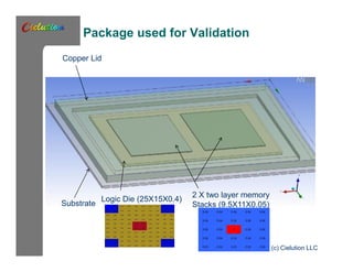
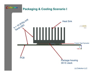
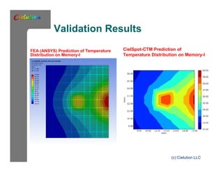
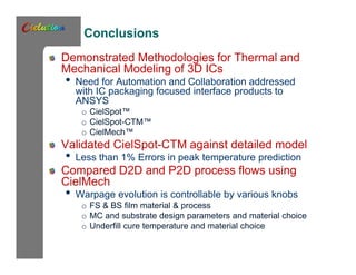
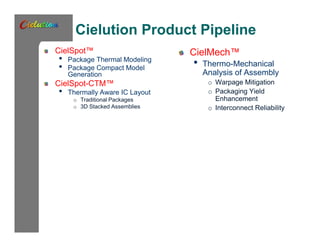
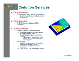
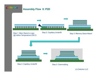
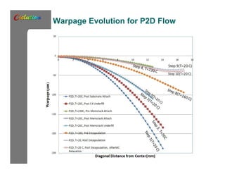
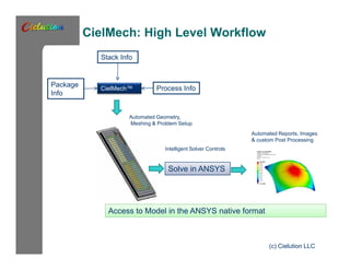
The document discusses techniques for thermomechanical modeling of 3D integrated circuits. It introduces Cielution's product pipeline including CielSpot for package thermal modeling and compact model generation, CielSpot-CTM for thermally aware IC layout, and CielMech for thermo-mechanical analysis. Cielution provides expertise in thermal and mechanical simulation along with tools expertise in ANSYS, Icepak, Fluent, etc. The document highlights challenges like warpage in 3D IC assembly and demonstrates Cielution's tools for modeling assembly processes, predicting warpage evolution, and validating compact thermal models against detailed simulations within 1% error.


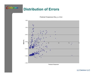
![A Boundary Condition Dependent Compact Model for 3D IC packages
[DT] = [C] * [Q]
• [DT] - Distribution of temperature rise over ambient (T rise
vector)
• [C] – Coefficient Matrix
• [Q] – Power (heat distribution) vector.
Linear superposition based compact modeling
approaches for non uniform heat loads are well
documented:
• Linear Superposition Speeds Thermal Modeling (Part I & Part
II), Stout, R., Power Electronics Technology, January 2007.
• Karimanal, K.,Chip-Package Thermal Co-Simulation
Technique for Thermally Aware Chip Design (Itherm, 2010)
• Park, J. H. et al. “fast thermal analysis of vertically integrated
circuits (3-d ICs)using power blurring method”, (ASME
Interpack 09)
(c) Cielution LLC](https://image.slidesharecdn.com/cielutionimapsshortpresentationpublic-141002164219-phpapp01/85/Cielution-imaps-short_presentation_public-24-320.jpg)