1) The document discusses the use of Flexible AC Transmission Systems (FACTS) devices like Thyristor Controlled Series Capacitor (TCSC) and Thyristor Controlled Reactor (TCR)-based Static VAR Compensator (SVC) to enhance power quality and transmission capability.
2) It presents simulation models of TCSC and TCR-SVC developed using MATLAB/Simulink. The simulations show that these FACTS devices can effectively reduce voltage drops, electrical losses in long transmission lines, and improve stability.
3) Student feedback indicates the models are easy to use and effective for learning about controlled reactor compensators, series capacitor compensators, and reactive power/voltage
![ ISSN: 2088-8694
IJPEDS Vol. 6, No. 1, March 2015 : 10 – 17
12
SVC Configurations: Providing reactive shunt compensation with shunt-connected capacitors and
reactors is a well-established technique to get a better voltage profile in a power system [2]. The basic form
of reactive power compensation required, to compensate reactive power loads, is the fixed shunt capacitors
being well distributed across the network and located preferably closed to the loads. This would ensure
reasonable voltage profile during steady state condition. However, this may not be adequate to ensure
stability under overload or contingency conditions. Shunt capacitors are inexpensive but lack dynamic
capabilities, thus some form of dynamically controlled reactive power compensation becomes essential. The
phase angle between the end voltages, determined by the real component of the line current, is not affected
by the shunt compensation. Similarly, adding a reactor instead of a capacitor in shunt will reduce the voltage.
Instead of mechanical switching (using circuit breakers) of these devices, we can use thyristor valves, thereby
increasing the control capability radically. This approach is called static VA R compensation (SVC).
Figure 2. Basic configuration static var compensator
SVC can be of one of the following types:
1. Thyristor controlled Reactor (TCR)
2. TCR plus Fixed Capacitor (FC)
3. Thyristor switched Capacitor (TSC)
4. TSC plus TCR
Figure 2 is a one-line diagram of a typical static VAR system for the transmission application. TSC
plus TCR is very popular and most effective. Fig 3 gives the general idea of realization of SVC using TSC
plus TCR scheme. The idea is to sense the voltage of the line and keep it stable by introducing capacitance or
inductance in the circuit.
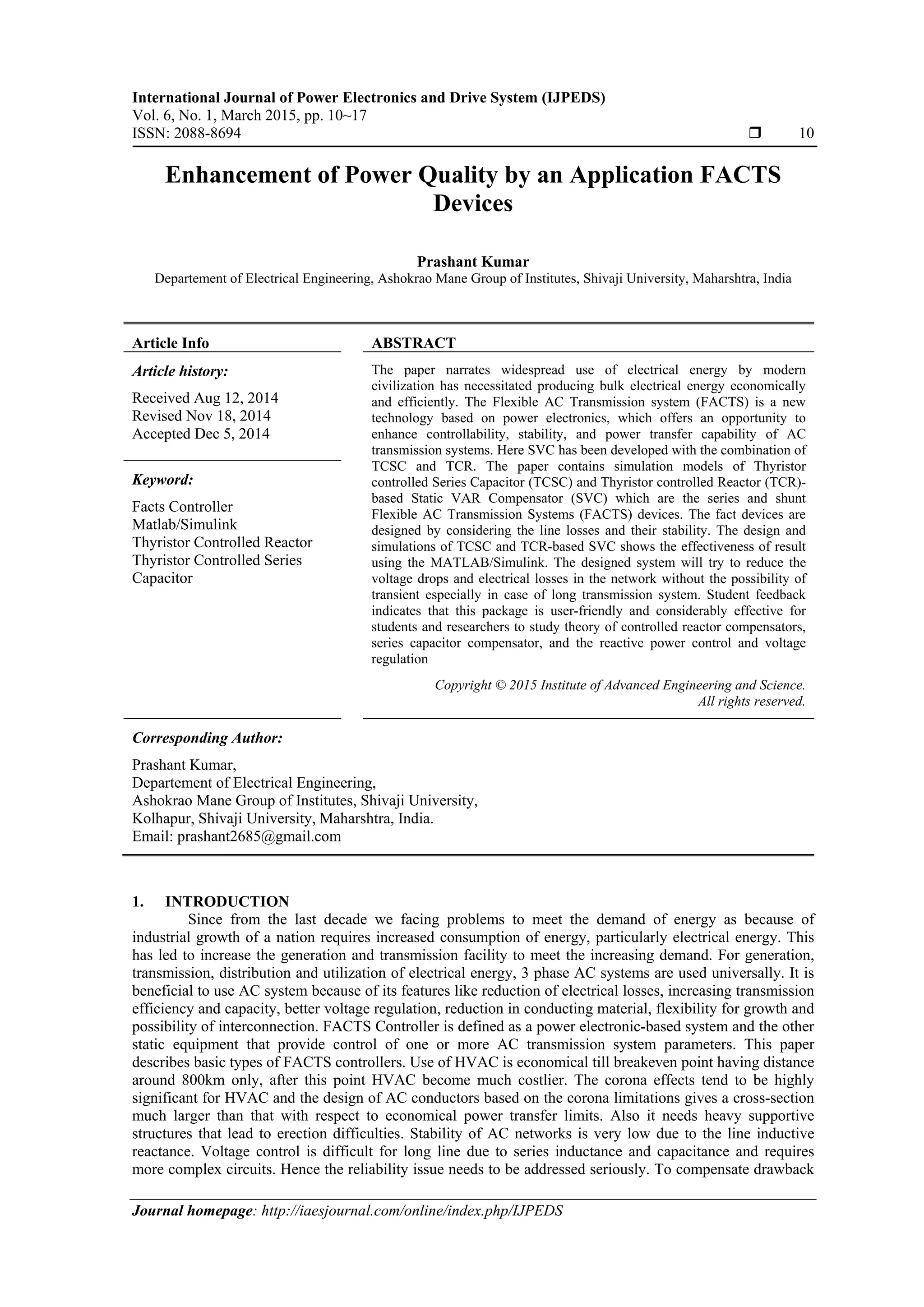
The Figure 3 presents an equivalent circuit of the TCR. The TCR consists of two thyristor in anti-
parallel, a reactor. Also in the three phase applications, the basic TCR elements are connected in delta. A
SMIB system with a TCR based SVC as shown in Figure 4. The shunt controller is injects current into the
line at point of common coupling (PCC). The main function of TCR is to current controlled by controlling
the firing angles of thyristor. So obviously power can be controlled. Since control can be achieved in every
cycle of the voltage waveform by (controlling the conduction time of thyristors), the control is very fast and
accurate.
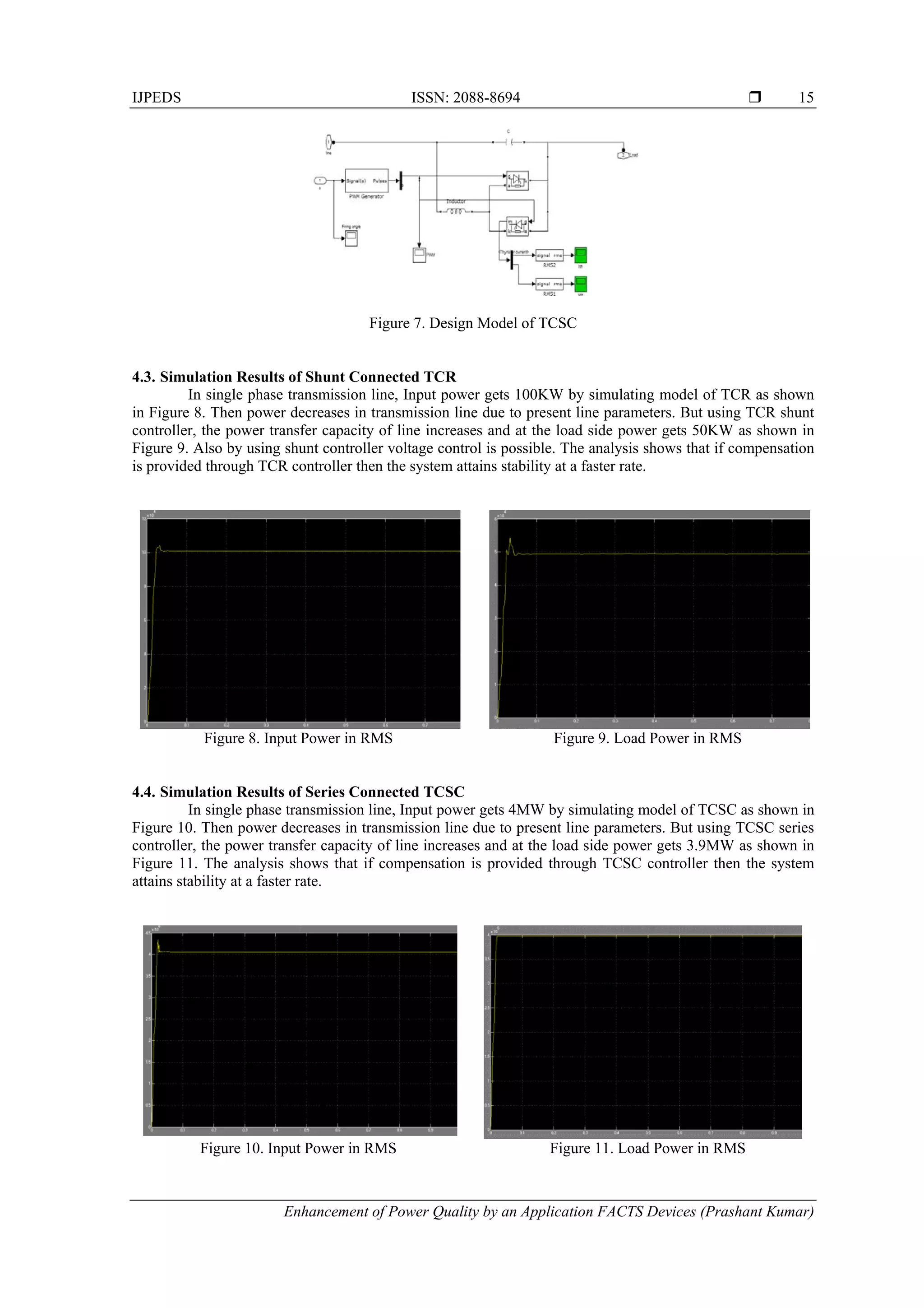
Figure 3. Basic structure of TCR Figure 4. SMIB system with a TCR based SVC](https://image.slidesharecdn.com/0218sep146551enhancementofpowerqualityfactsedit-171214065613/75/Enhancement-of-Power-Quality-by-an-Application-FACTS-Devices-3-2048.jpg)
![IJPEDS ISSN: 2088-8694
Enhancement of Power Quality by an Application FACTS Devices (Prashant Kumar)
13
3. THEORY OF THYRISTOR CONTROLLED SERIES CAPACITOR (TCSC)
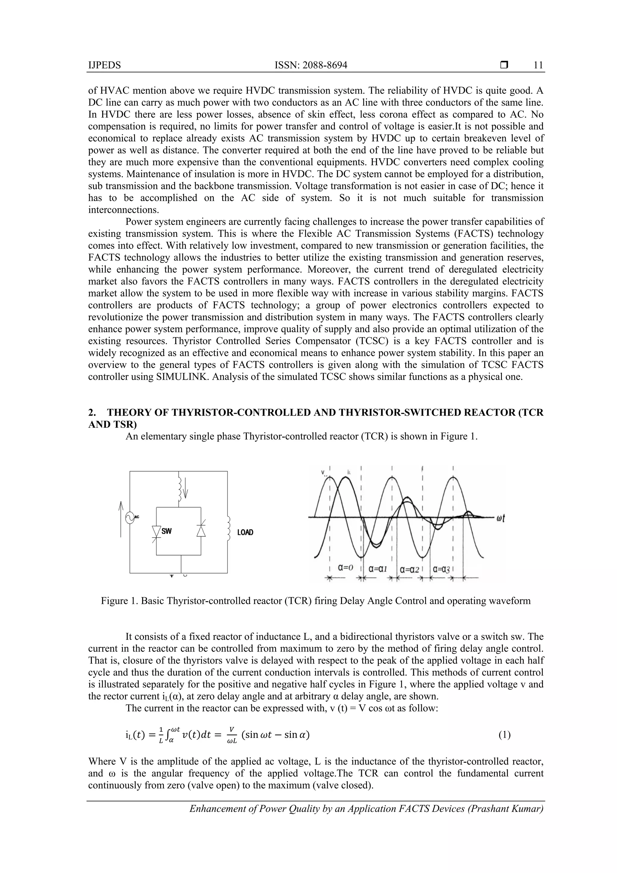
The basic conceptual TCSC module comprises a series capacitor, C, in parallel with a thyristor-
controlled reactor, LS, as shown in Figure 5(a). A TCSC is a series-controlled capacitive reactance that can
provide continuous control of power on the ac line over a wide range. From the system viewpoint, the
principle of variable-series compensation is simply to increase the fundamental-frequency voltage across
fixed capacitor (FC) in a series- compensated line through appropriate variation of the firing angle [4]. This
enhanced voltage changes the effective value of the series-capacitive reactance.
Simple understanding of TCSC functioning can be obtained by analysing the behaviour of a variable
inductor connected in parallel with an FC, as shown in Figure 5(b).
(a) (b)
Figure 5. TCSC Module (a) Basic module and (b) A Variable inductor connected in shunt with FC
The equivalent impedance, Zeq, of this LC combination is expressed as:
)()
1
( jwL
wc
jZeq
(2)
The impedance of the FC alone, however, is given by –j(1 / C).
If C− (1 / L) > 0 or, in other words, L > (1 / C), the reactance of the FC is less than that of
the parallel-connected variable reactor and that this combination provides a variable-capacitive reactance are
both implied. Moreover, this inductor increases the equivalent capacitive reactance of the LC combination
above that of the FC. If C− (1 / L) = 0, a resonance develops that results in an infinite capacitive
impedance an obviously unacceptable condition. If, however, C−(1 / L) < 0, the LC combination
provides inductance above the value of the fixed inductor. This situation corresponds to the inductive mode
of the TCSC operation. In the variable-capacitance mode of the TCSC, as the inductive reactance of the
variable inductor is increased, the equivalent-capacitive reactance is gradually decreased. The minimum
equivalent-capacitive reactance is obtained for extremely large inductive reactance or when the variable
inductor is open-circuited, in which the value is equal to the reactance of the FC itself. The behaviour of the
TCSC is similar to that of the parallel LC combination. The difference is that the LC-combination analysis is
based on the presence of pure sinusoidal voltage and current in the circuit, whereas in the TCSC, because of
the voltage and current in the FC and thyristor-controlled reactor (TCR) are not sinusoidal because of
thyristor switching.
The series compensation provided by the TCSC can be adjusted rapidly to ensure specified
magnitudes of power flow along designated transmission lines. This condition is evident from the TCSC’s
efficiency, that is, ability to change its power flow as a function of its capacitive-reactance setting:
sin
)(
21
12
XCXL
VV
P
(3)
Where:
P12= the power flow from bus 1 to bus 2
V1, V2 = the voltage magnitudes of buses 1 and 2, respectively
XL = the line-inductive reactance
XC = the controlled TCSC reactance combined with fixed-series- capacitor reactance
d = the difference in the voltage angles of buses 1 and 2](https://image.slidesharecdn.com/0218sep146551enhancementofpowerqualityfactsedit-171214065613/75/Enhancement-of-Power-Quality-by-an-Application-FACTS-Devices-4-2048.jpg)
![ ISSN: 2088-8694
IJPEDS Vol. 6, No. 1, March 2015 : 10 – 17
16
4.5. PID Controller is Designed for TCR and TCSC
The PID controller is a very simple controller, but the major drawback is that there is no analytical
way of finding the optimal set of parameters KP, KI, and KD. The conventional Proportional Integration
Derivative (PID) structure remains the controllers of choice in many industrial applications because of its
structural simplicity, reliability and the favourable ratio between performance and cost. Beyond these
benefits, this controller also offers simplified dynamic modelling, lower user skill requirement, and minimal
development effort. The design of PID controller is same for TCR and TCSC.
5. CONCLUSION
This paper presents the TCR and TCSC controller developed by using the MATLAB/Simulink. The
developed software package consists of two main application menus which are the TCSC menu and the TCR-
based SVC menu. These menus include seventeen simulation models about different applications of TCSC
and TCR-based SVC. The effects of the TCSC and TCR-based SVC on load voltage have been studied in the
single-phase and three-phase system with static load types. Besides, a single-machine infinite-bus system
with static load type has been studied. The studied power systems are two and three bus with a long
transmission line model. In this paper, we have demonstrated few applications of the FACTS controller such
as a single-phase system with TCSC for the static load, and a SMIB system with TCR-based SVC for the
static load. The simulation results show that significant improvement on voltage regulation and reactive
power compensation is obtained by using the TSC and the TCR-based SVC. A survey which has six
statements regarding facts controller was prepared. According to the survey, majority of the students thought
that the MATLAB software package is user-friendly, easy to understand and several system parameters could
be changed easily. This package is considerably effective for students and instructors to study theory of
controlled compensators, the reactive power control and voltage regulation. Future work will concentrate on
designing laboratory prototypes of the TCSC and the TCR-based SVC devices to provide the ability to
experimentally verify the MATLAB software package.
REFERENCES
[1] NG Hingorani, L Gyugyi, Understanding FACTS, IEEE Press, New York, 1999.
[2] Aboytes F, Arroyo G, Villa G. Application of Static V AR Compensators in Longitudinal Power Systems, IEEE
Trans on PAS, 1983; 102: 3460-3466.
[3] R Arulmozhiyal, K Baskaran, Implementation of a Fuzzy PI Controller for Speed Control of Induction Motors
Using FPGA, Journal of Power Electronics, 2010; 10: 65-71.
[4] LAS Pilotto, AR Carvalho, A Bianco, WF Long, FL Alvarado, CL DeMarco, A Edris, The Impact of Different
TCSC Control Methodologies on the Subsynchronous Resonance Problem, Proceedings of EPRI Conference on
FACTS, Washington, DC, 1996.
[5] N Christl, P Luelzberger, M Pereira, K Sadek, PE Krause, AH Montoya, DR Torgerson, BA Vossler, Advanced
Series Compensation with Variable Impedance, Proceedings of EPRI Conference on FACTS, 1990.
[6] RM Mathur, RK Varma, Thyristor-Based FACTS Controllers for Electrical Transmission Systems, IEEE Press,
USA, 2002
[7] M Hedayati, Technical specification and requirements of static VAr compensation (SVC) protection consist of TCR,
TSC and combined TCR/TSC, Proceedings of the 39th International Universities Power Engineering Conference,
Bristol, UK, 2004; 1: 261–264.
[8] CIGRE Working Group 14.18, Thyristor-Controlled Series Compensation, Technical Brochure, Paris, 1996.
[9] A Ghosh, G Ledwich, Modelling and control of thyristor controlled series compensators, IEE Proc. Generation
Transmission and Distribution, 1995; 142(3): 297-304.
[10] D Zhang, et al., Common Mode Circulating Current Control of Interleaved Three-Phase Two-Level Voltage-Source
Converters with Discontinuous Space-Vector Modulation, 2009 IEEE Energy Conversion Congress and Exposition,
2009; 1(6): 3906-3912.
[11] A Gelen, T Yalcinoz, The behaviour of TSR-based SVC and TCR-based SVC installed in an infinite bus system,
Proceedings of the IEEE 25th
Convention Electrical and Electronics Engineers in Israel, Eilat, Israel, 2008; 120–
124.
[12] Z Yinhai, et al., A Novel SVPWM Modulation Scheme, Applied Power Electronics Conference and Exposition,
2009. APEC 2009. Twenty-Fourth Annual IEEE, 2009; 128-131.
[13] BK Johnson, Simulation of TSC and TSSC, Proceedings of the IEEE Power Engineering Society Winter Meeting,
Columbus, USA, 2001; 637–63.](https://image.slidesharecdn.com/0218sep146551enhancementofpowerqualityfactsedit-171214065613/75/Enhancement-of-Power-Quality-by-an-Application-FACTS-Devices-7-2048.jpg)


![A Seminar_Presentation_on_FACTS_DEVICES].pptx](https://cdn.slidesharecdn.com/ss_thumbnails/aseminarpresentationonfactsdevices-250415070810-17213f59-thumbnail.jpg?width=640&height=640&fit=bounds)