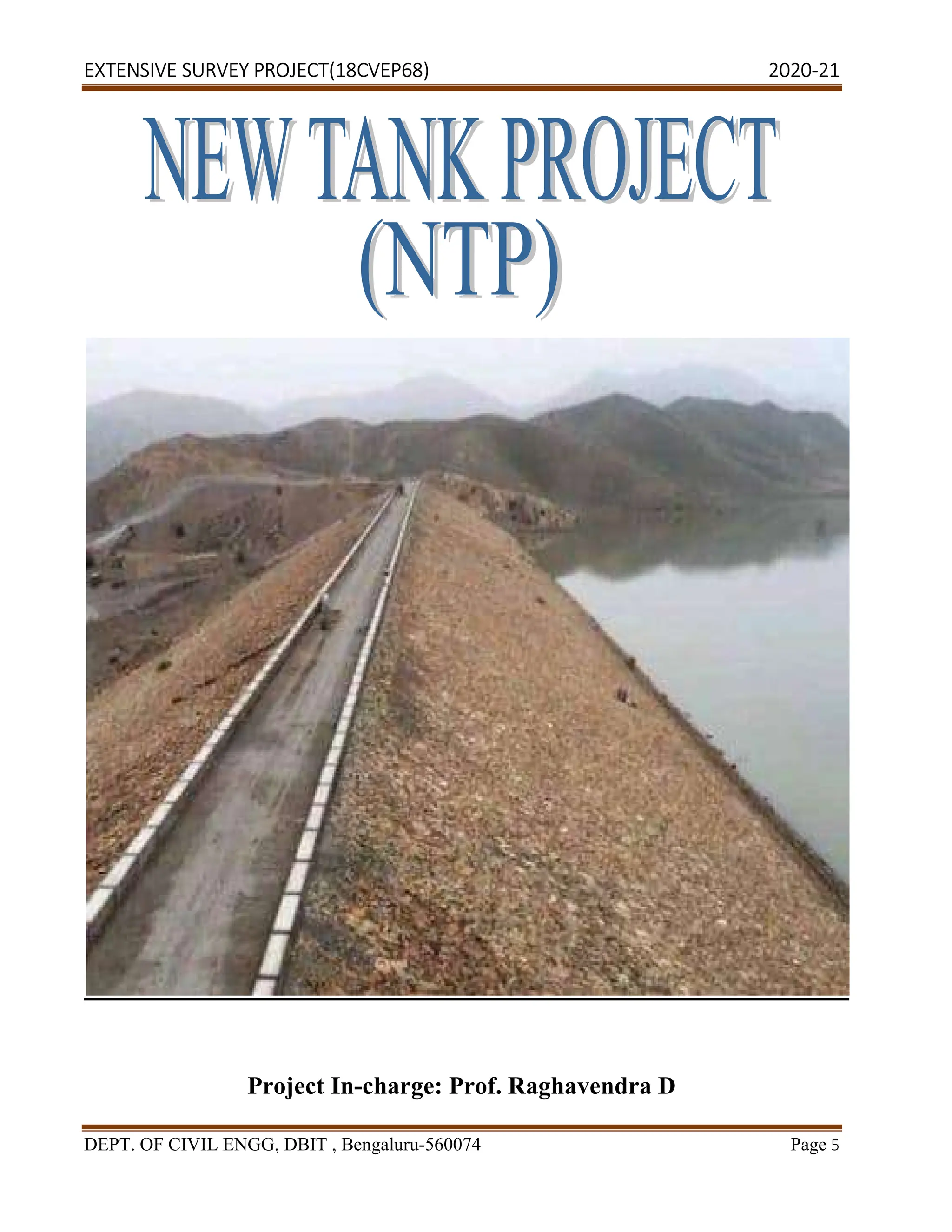
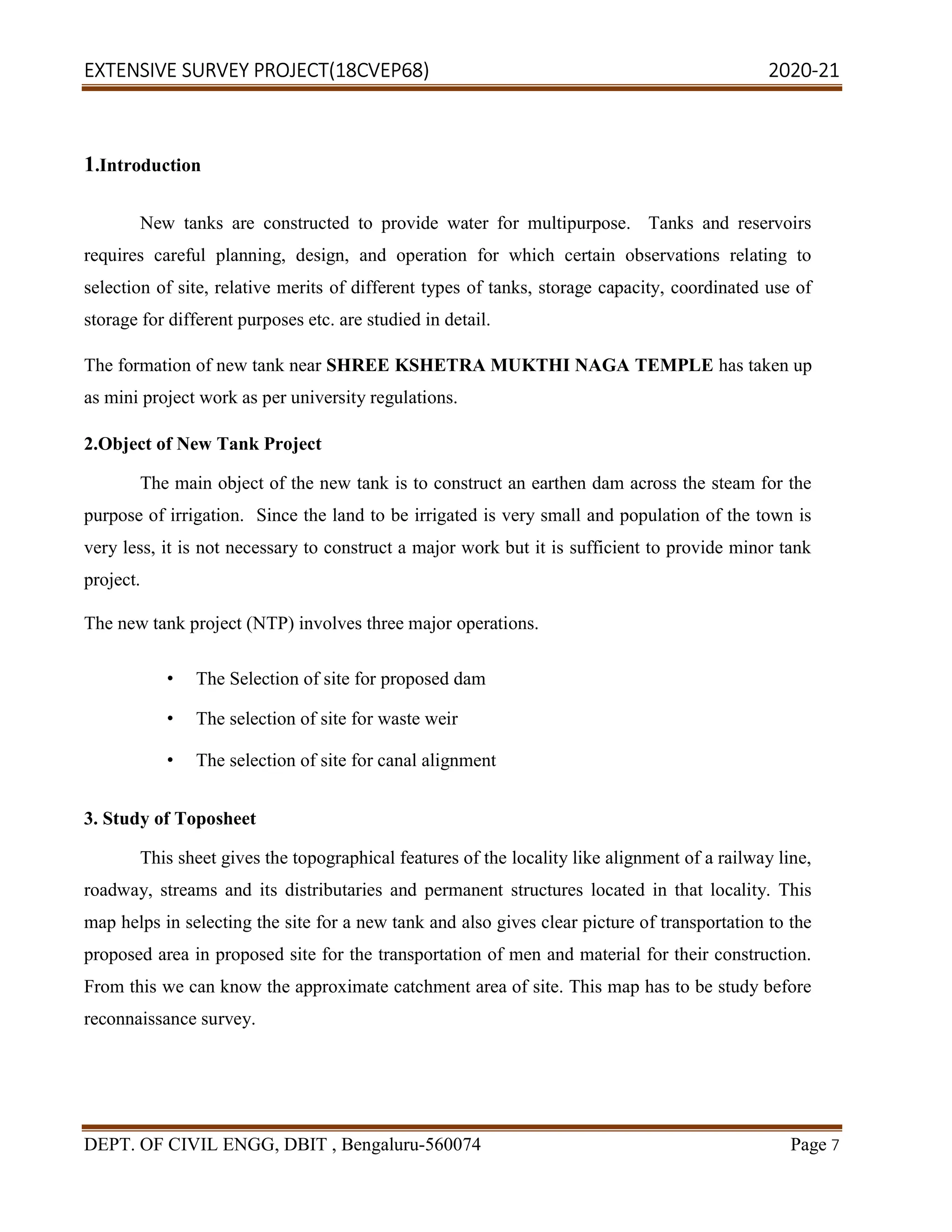
The document is a project report submitted by 7 students for their 6th semester civil engineering program. It details an extensive survey project conducted from March 29th to April 12th, 2021 in Kempegowda Layout, Bengaluru. The project involved selecting sites for a new reservoir, dam, and canal to provide water for irrigation near Shree Kshetra Mukthi Naga Temple. Key aspects surveyed included reservoir requirements and planning, dam design options, and canal lining material needs. Dimensions for an earthen dam were also designed based on standards.
![EXTENSIVE SURVEY PROJECT(18CVEP68) 2020-21
DEPT. OF CIVIL ENGG, DBIT , Bengaluru-560074 Page 12
Especially in south India, where such works are very common. This terminology is limited
to India only. There is no technical relationship between the reservoir and tank except that a large
sized tank will be termed as reservoirs. More over a reservoir will be generally formed by dam of
any materials such as masonry dam. Concrete dam, earthen dam (tank) is generally said to be
formed to earthen dam as earthen bund. Most of the existing tank in South India passes a maximum
depth of 4.5m while a few is as deep as 7.5m to 9.5m and only a few are exceptional one which
exceeds 11m depth. When the depth of the tank exceeds 12m or so then the tank is generally said to
be reservoir.
Like all earthen bunds, tank bunds are generally provided with sluice or outlets for
discharging water from the tank for irrigation and other purposes. These tank sluice may be pipes or
rectangular as arched opening passing near the base of the bund. For carrying the water to the dam
downstream side channel below the bund transporting at distance where required through pipes or
canals. Sometimes these supply sluices may not be carried adjacent to it through hill side one end of
the bond.
Similarly, tanks are provided with the arrangements for the spilling the excess, surplus water that
may be enter into the tank so as to avoid over lapping of the tank bund. These surplus escape
arrangements may be in the form of the tank bund or some other arrangements like siphon spillway
may be provided in the case of the earthen dam project. The surplus escape weir in a masonry weir
with its top i.e. crest level equal to full tank level [F.T.L] when the tank is full of up to F.T.L and
extra water come in, then it is discharged over the surplus escape weir, surplus escape weir will also
be designed that water level in the tank never exceeds the maximum water level, the top of the tank
bund will be kept at a level so as provided a suitable free board and the maximum water level
[M.W.L].
Since the surplus escape weir is a masonry weir then it will have to be properly connected to the
earthen bund by suitably designed tank connection.
Types of Levelling
Direct levelling
Indirect levelling](https://image.slidesharecdn.com/2-240320174630-b4be831e/75/Extensive-survey-project-vtu-pdfproject1-12-2048.jpg)
![EXTENSIVE SURVEY PROJECT(18CVEP68) 2020-21
DEPT. OF CIVIL ENGG, DBIT , Bengaluru-560074 Page 18
[U/S slope X Height + Top width + D/S slope X height] .............(1)
The day’s work is constructed at temporary benchmark established.
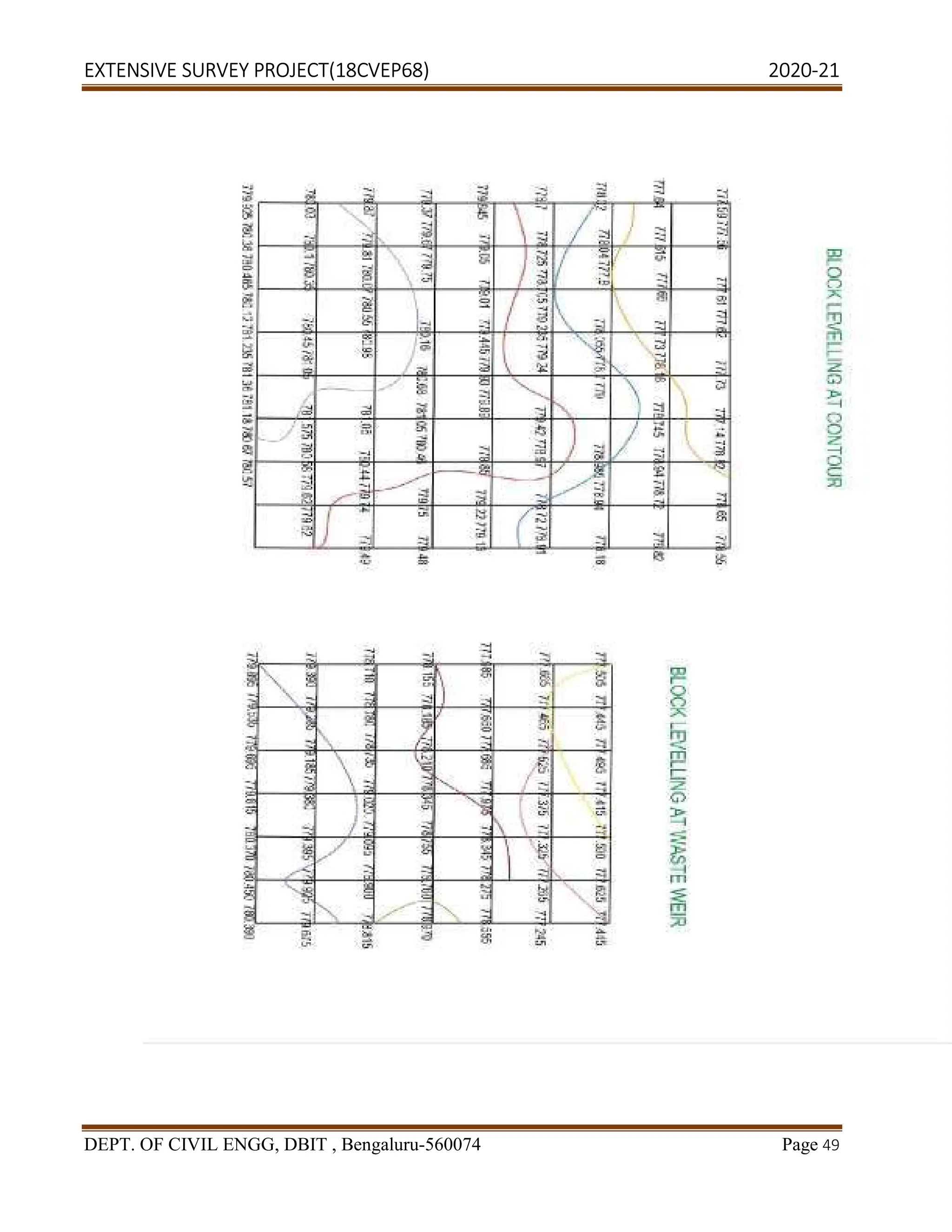
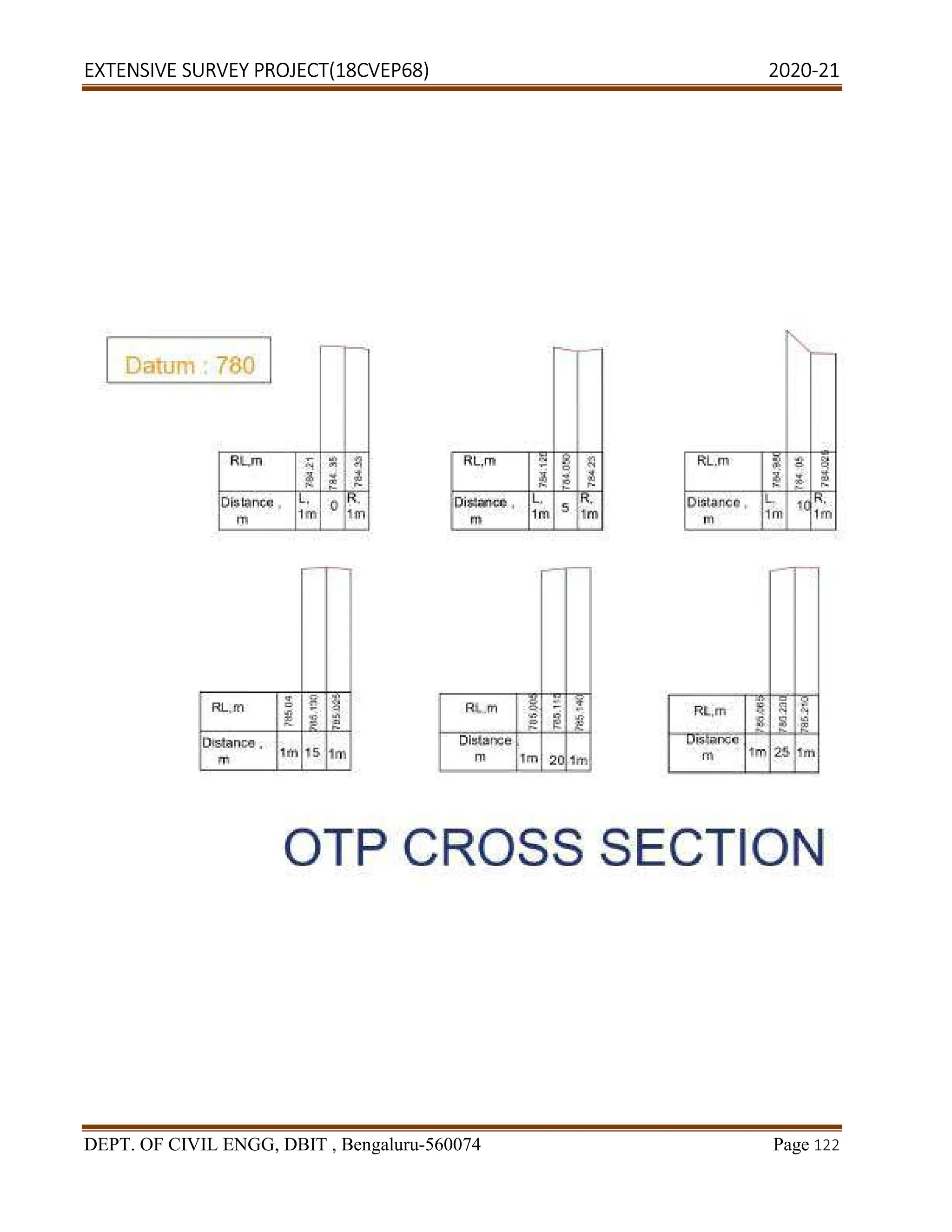
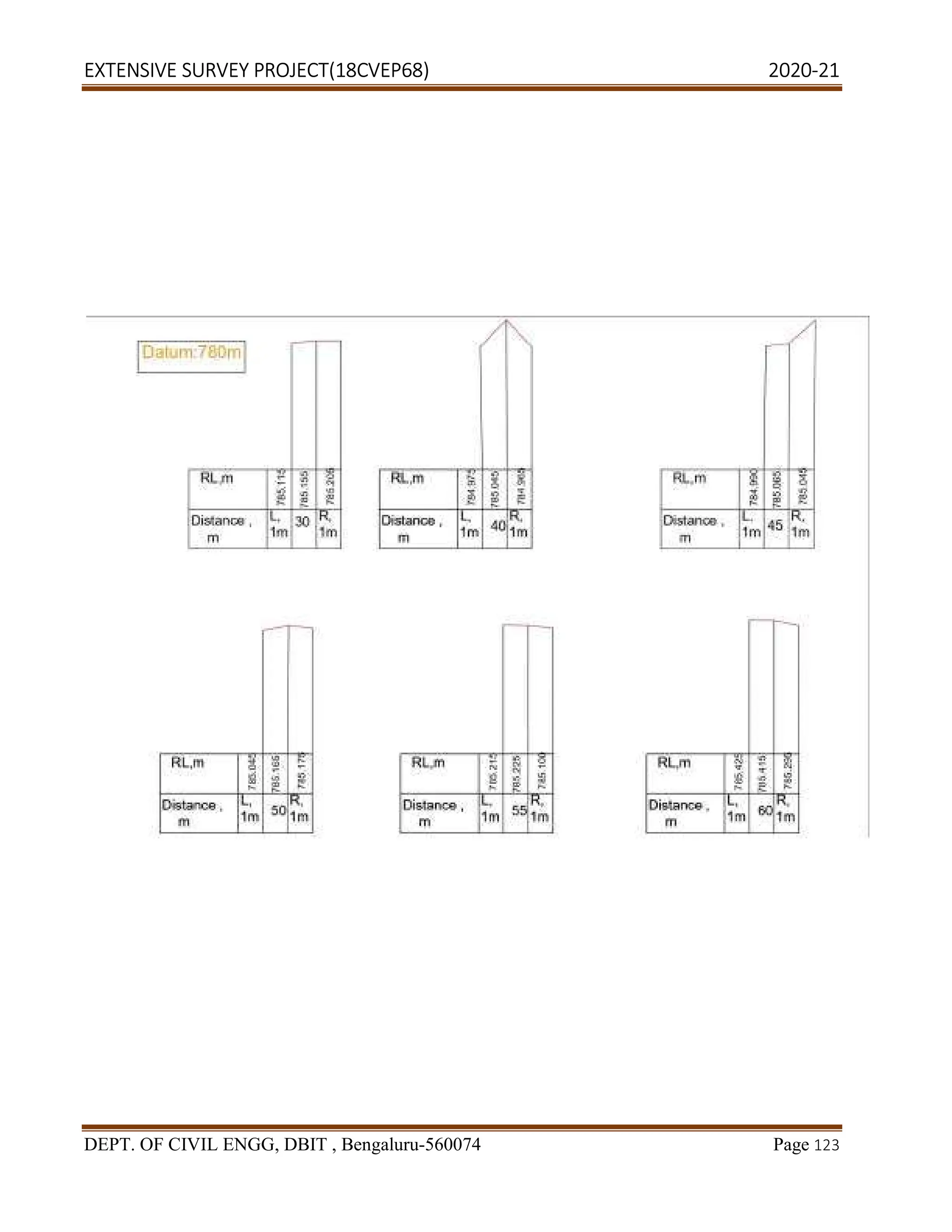
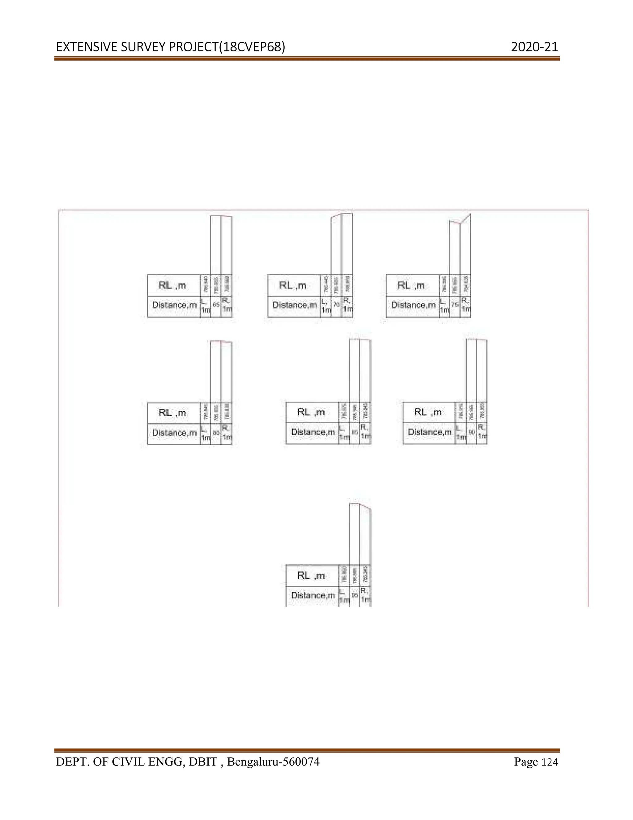
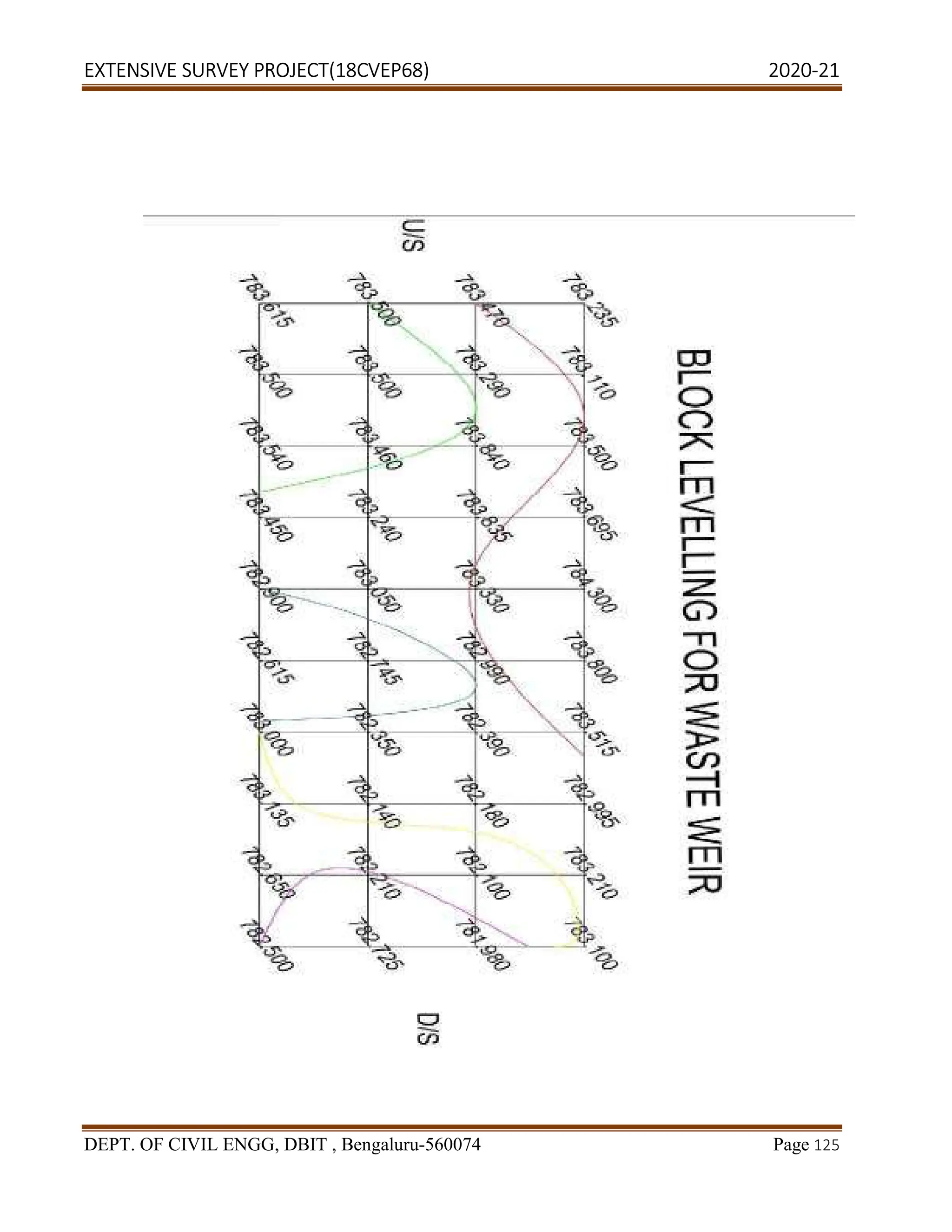
Bench Levelling at Waste Weir
• The top of the weir should be at FTL. Fix the centreline and mark left and right
points.
• Construct a block of 60m length on U/S side and 40m length D/S side.
• Carry out block levelling at every 5m interval.
• Work is started and closed at established bench mark.
Block Levelling at Tank Sluice
• RL of the canal at tank, take a point on the centre line of the bund.
• Construct a block of 30m along the centre line and 60m on side of the centreline.
• Divide this entire area into smaller block of 5m X 5m Carryout the block
levelling along the point.
• Start and close down the work with respect to the permanent benchmark.
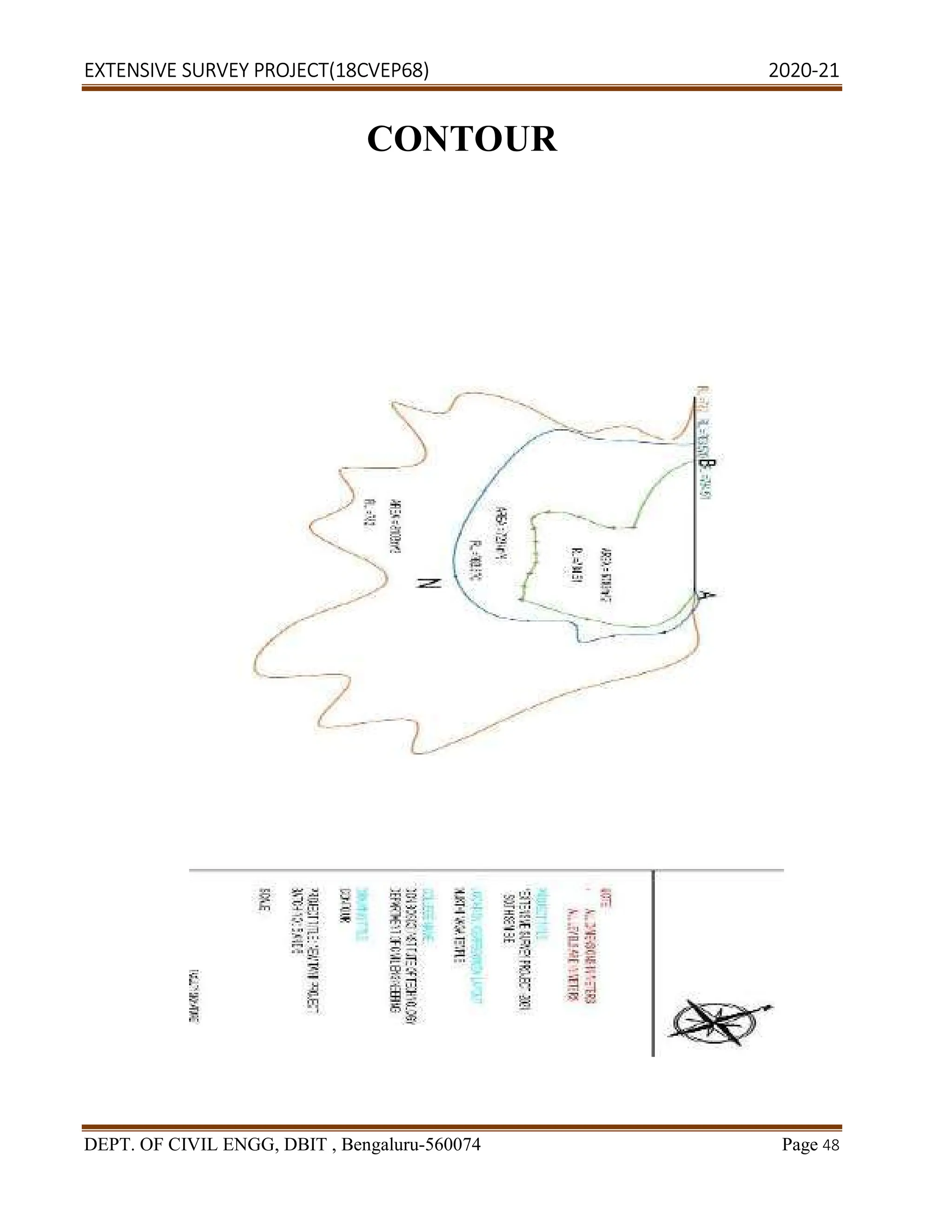
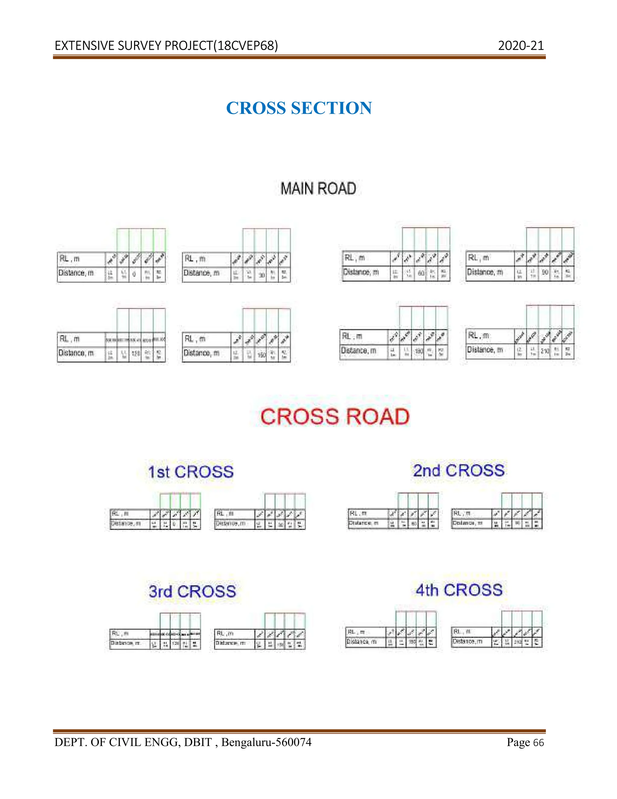
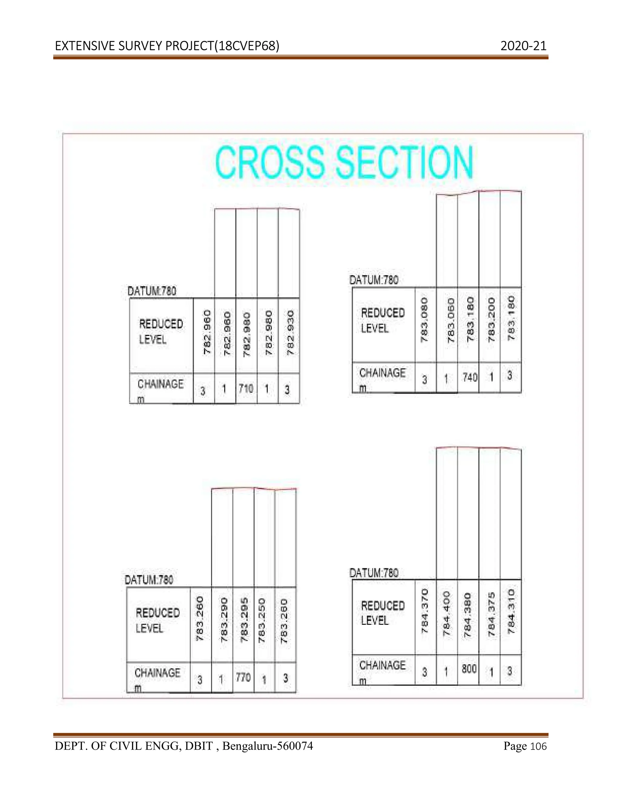
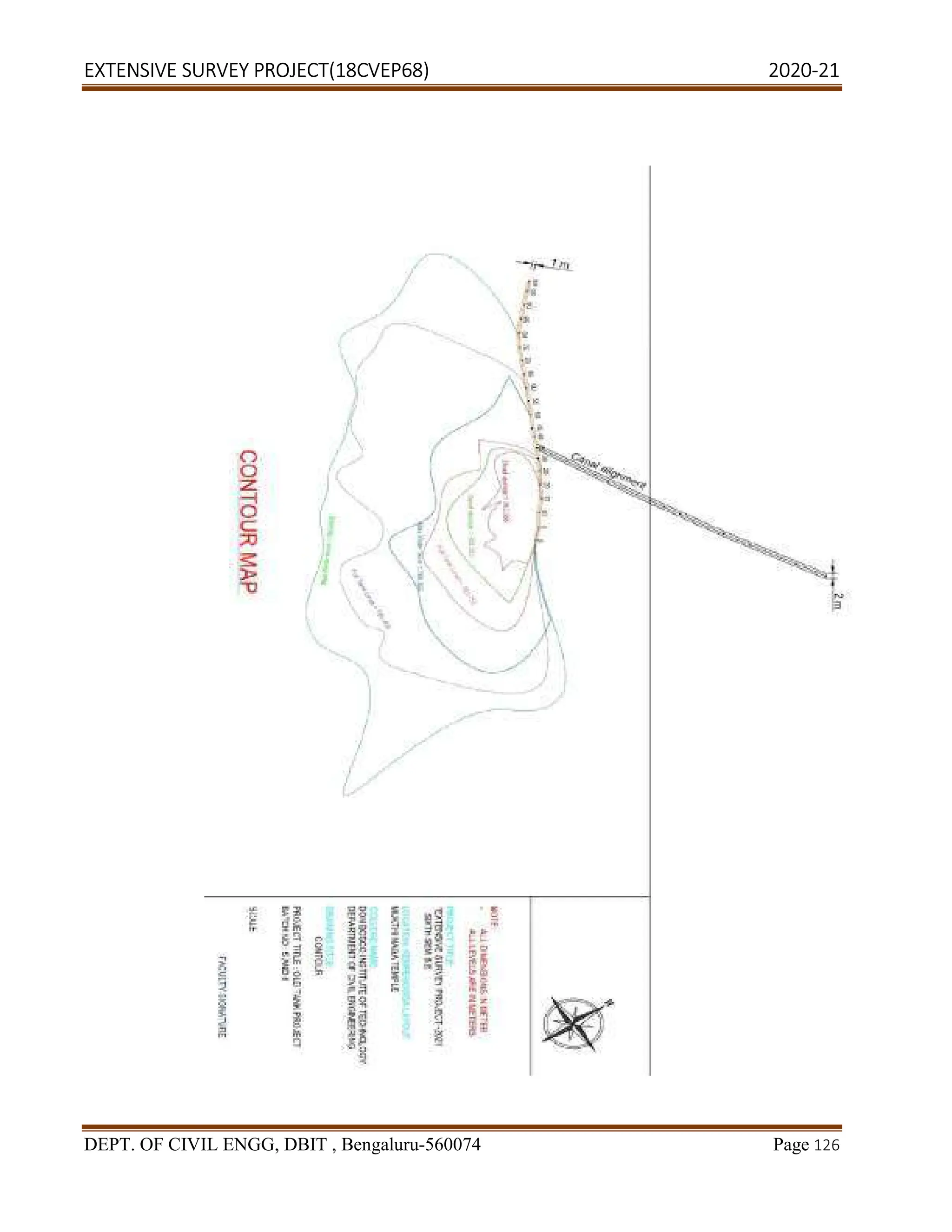
Survey for The Capacity Contour
In order to plot the contour FTL, LWL, MWL, surveying for water spread contours was conducted
due to certain physical constraints, indirect levelling is adopted.
Radial levelling is carried out at U/S side using the following procedure:
• Prismatic compass was fixed on the centreline of the bund such that main area
could be covered on the U/S side.
• Radial lines at an angle of 0,30,60,90,120,150 and 180 were set out from the
compass point.
• Fly levelling was adopted to carry benchmark from permanent benchmark to
compass point.
• Staff readings were taken along the radial lines at 15m interval.](https://image.slidesharecdn.com/2-240320174630-b4be831e/75/Extensive-survey-project-vtu-pdfproject1-18-2048.jpg)
![EXTENSIVE SURVEY PROJECT(18CVEP68) 2020-21
DEPT. OF CIVIL ENGG, DBIT , Bengaluru-560074 Page 19
• Cross – section were taken along with radial lines at 15m intervals.
• The cross section was increased along the radial lines such that the whole
upstream side is covered.
• The work is closed by the fly levelling on established benchmark.
Impartment Definition
Crop Period:
it is the time taken by crop from the instant of its sowing to harvesting.
Base Period:
It is the period during which the water supplied to the crops to bring the crop to maturity. The
base period is slightly less than the crop period. It is donated by the letter B.
Duty of Water:
It is defined as number of hectares brought to maturity by a constant flow of water per
second during the crop period or it is the relationship between the volume of water and area of crop
brought to maturity. It includes both cultivable and non-cultivable area. It is given by the formula
D= 864 B/∆
Where,
∆in Cm. [delta]
B in days [Base period]
D in hectares /cumecs. [Duty]
Delta:
Each crop requires certain quantity of water at regular intervals of time throughout its
period. If this total quantity of water is made to stand without any lose on an area, the depth
of water required per hectare for the full growth of crop is called as delta. It is expected by a
symbol.](https://image.slidesharecdn.com/2-240320174630-b4be831e/75/Extensive-survey-project-vtu-pdfproject1-19-2048.jpg)
![EXTENSIVE SURVEY PROJECT(18CVEP68) 2020-21
DEPT. OF CIVIL ENGG, DBIT , Bengaluru-560074 Page 23
10. Weir
Weir is a structure constructed at right angles to the direction of the flow. Its purpose is to
raise the water level and then divert it into the canal. As the tanks are the small storage works
constructed to meet the local requirements obvious by attempting is not made to contain full run off
coming down from the catchment area. It is therefore necessary to make suitable arrangement to
pass from the excess water beyond F.T.L. The structure constructed to provide passage to excess
water is called as “escape weir”. It is also called as a “Tank surplus weir”.
The Water starts spilling over the weir as soon as tank is filled up to its crest. However temporarily
due to rush of incoming water. The level in the tank raises above F.T.L., the new level is reached is
called as “maximum water level” [M.W.L.]. It depends on the extent of the flood for the design
purpose M.W.L is calculated taking into the account maximum flood discharge likely to carry and
water may be available at the site for escape weir. The surplus as spill way water is carried down
through a channel which is generally a natural discharge and has an enough capacity. As weir may
be constructed in the masonry, rock fill, cement concrete etc.
Types of Weir
Escape weir constructed in the tank irrigation system is similar to a diversion weir are
constructed across the river channel.
It may be classified as following types;
1.Masonry Weir
• Masonry with the horizontal floor.
• Masonry weir with depressed floor.
• Masonry weir with stepped floor.
2.Rock Fill Weir
3.Concrete Weir](https://image.slidesharecdn.com/2-240320174630-b4be831e/75/Extensive-survey-project-vtu-pdfproject1-23-2048.jpg)
![EXTENSIVE SURVEY PROJECT(18CVEP68) 2020-21
DEPT. OF CIVIL ENGG, DBIT , Bengaluru-560074 Page 24
11. Selection of Site for A Weir
Following are the point may be taken into consideration while selecting a site for a tank weir.
• Tank weir performs the function of the surplus excess flow therefore it is
preferable to locate the weir in a natural saddle away from the tank bund.
• To carry surplus flow existence of a well-defined escape channel is very
necessary at a site selected for the construction of a weir.
• The saddle where natural surface level us approximately same as tank level [FTL]
should be given first performance.
• Hard foundation if available at the site reduces the cost of the construction.
• When a site is away from the tank bund is not available as for as possible weir
may be located on one end of the tank bund.
• Surplus weir may be hosed in the body of the tank bund only as a last resort.
• Care should be taken to see that escape channel surplus water is not likely to
damage cultivated land.
12. Lining of Canal
The impervious layer which protects the beds and sides of the canal is called canal lining.
Necessity of Canal Lining
Following are the necessity of the canal lining.
• To minimize the seepage losses in the canal.
• To increase the discharge in canal selection by increasing the velocity.
• To prevent erosion of the bed and sides due to high velocity.
• To reduce maintenance of canal.](https://image.slidesharecdn.com/2-240320174630-b4be831e/75/Extensive-survey-project-vtu-pdfproject1-24-2048.jpg)
![EXTENSIVE SURVEY PROJECT(18CVEP68) 2020
DEPT. OF CIVIL ENGG, DBIT , Bengaluru
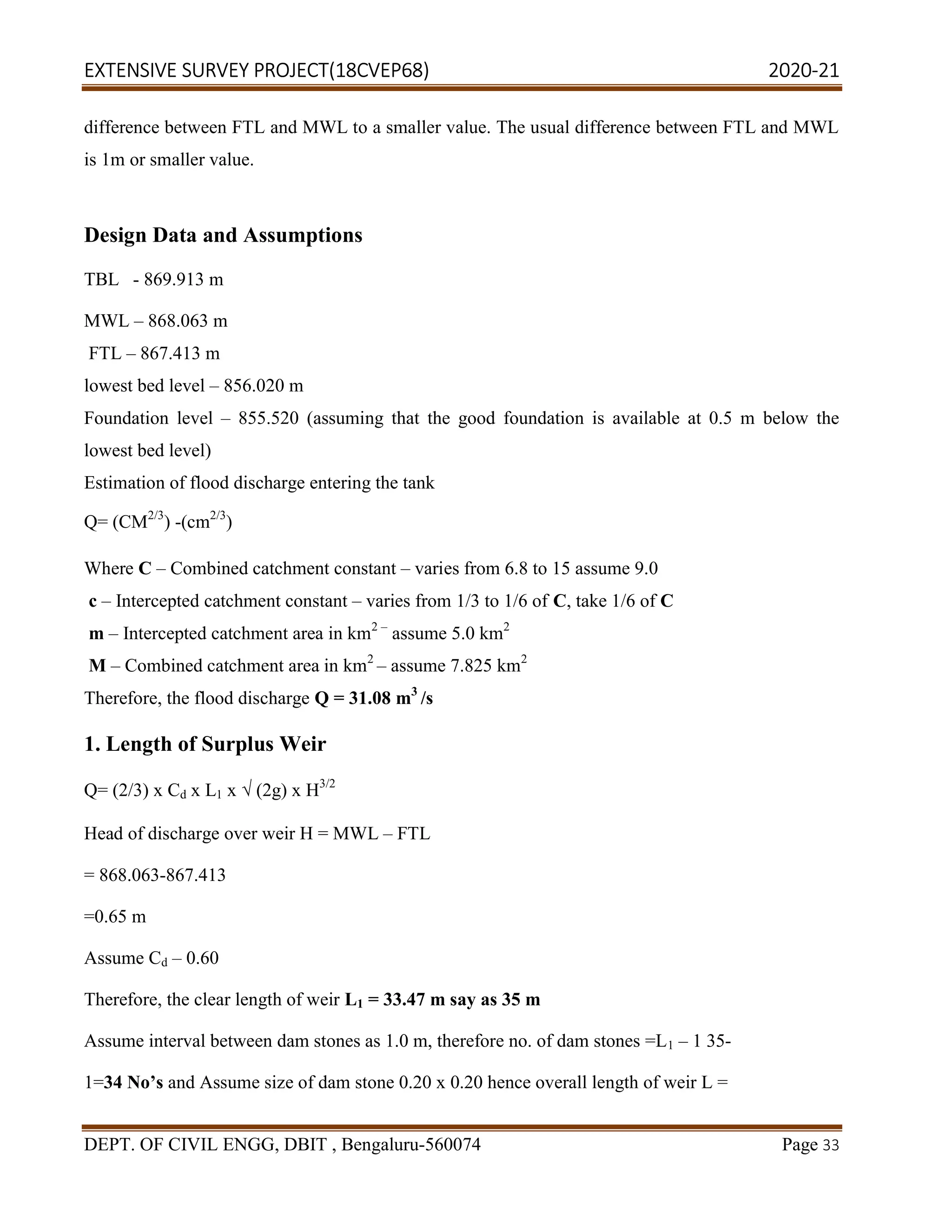
[L1+ (width of dam stone x no’s of stones)]
L=[35+(0.20 X 34)] = 41.80 m.
2. Dimensions of Weir
Structural height of weir
Crest level- 867.413 m (FTL)
Top of dam stone – 868.063 m(MWL)
Ground level – 856.020 m
Downstream-
Top of foundation concrete TFL
Height of weir above foundation H = (FTL
Structural height of weir = H + (top of dam stone
Crest width / top width
a =0.55(√ (H) +√ (h))
Where: h = head over weir = (MWL
Therefore, top width of weir
Where:
specific weight of masonry, S = 2.4kN/m3
Therefore, base width of weir
3. Protection Work
Abutment
Height of abutment above foundation (TBL
Top width = 0.50 m (min)
(18CVEP68) 2020
CIVIL ENGG, DBIT , Bengaluru-560074
[L1+ (width of dam stone x no’s of stones)]
m(MWL)
foundation concrete TFL – 855.520 m
oundation H = (FTL – TFL) = 11.890 m
Structural height of weir = H + (top of dam stone level – crest level) = 12.543 m
ead over weir = (MWL – FTL) = 0.65m
Therefore, top width of weir a =2.34say as 2.4m
specific weight of masonry, S = 2.4kN/m3
Therefore, base width of weir b = 10.60 m
Height of abutment above foundation (TBL-TFL) Ha= 14.393m
(18CVEP68) 2020-21
Page 34
m](https://image.slidesharecdn.com/2-240320174630-b4be831e/75/Extensive-survey-project-vtu-pdfproject1-34-2048.jpg)
![EXTENSIVE SURVEY PROJECT(18CVEP68) 2020-21
DEPT. OF CIVIL ENGG, DBIT , Bengaluru-560074 Page 36
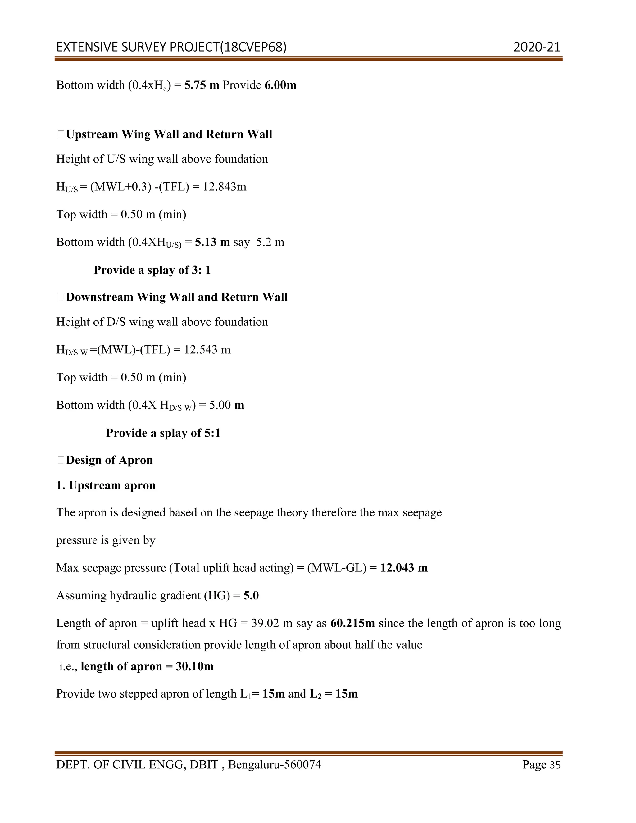
Thickness of solid apron = residual seepage pressure / (Sc – 1)
Where: residual seepage pressure = max seepage pressure – seepage pressure lost
= max seepage pressure – (seepage length / HG)
Note: Seepage length = length of apron therefore residual seepage pressure = 2.005
Sc= specific gravity of concrete = 2.25
Therefore, thickness of 1st
apron = 1.604 m
Hence provide thickness of 2nd
apron of about 50% of 1st
apron i.e.=0.802 m
Downstream Apron
Generally, no aprons are required on D/S side of weir however, cement grouting and sheet piling is
done on the area immediately above weir to avoid percolation of water into soil
C) Determination of Discharge Required
Assume,
Culturally Commanded Area= 600 hectares
Area under Crop 1 (Ragi) = 60 % of CCA
Crop 2 (Vegetables) = 40 % of CCA
The major crops grown in this region and necessary data are calculated and tabulated below
CROPS RAGI VEGETABLES
AREA UNDER[A] CROP - hectares 402 268
BASE PERIOD[B]- days 120 90
AMOUNT OF WATER REQUIRED (∆ -
m)
0.30 0.20
DUTY[D] D = 3.64 x (B / ∆) (hectare/cumecs) 3456 3888
DISCHARGE[Q] Q = A / D (m3
/sec) 0.1163 0.0689](https://image.slidesharecdn.com/2-240320174630-b4be831e/75/Extensive-survey-project-vtu-pdfproject1-36-2048.jpg)
![EXTENSIVE SURVEY PROJECT(18CVEP68) 2020-21
DEPT. OF CIVIL ENGG, DBIT , Bengaluru-560074 Page 39
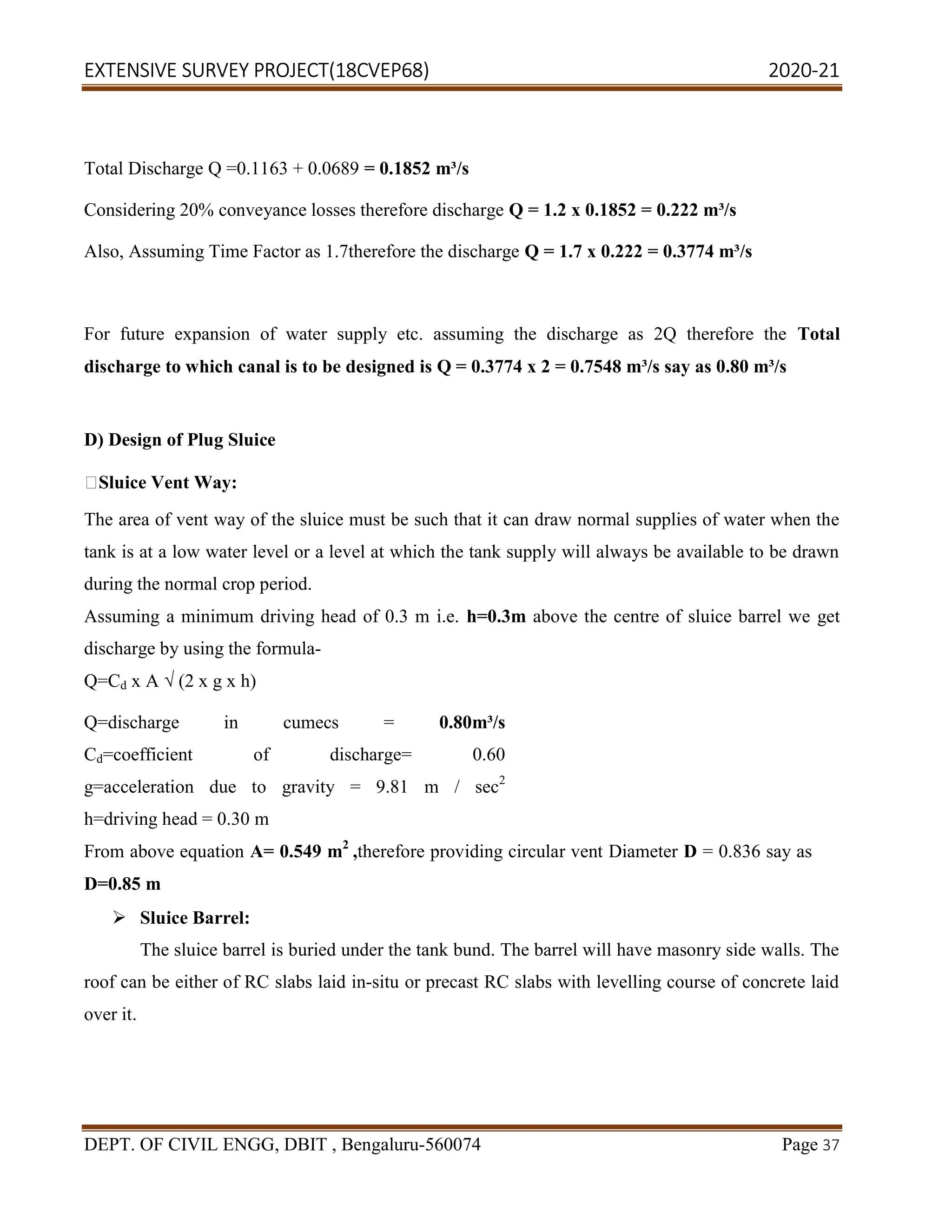
1.89= (4.25-2.83D) D + 1xD2
solving for D we have D = 0.599m say as 0.60 m thus by Providing
0.30 m free board total depth of canal is 0.90 m.
Therefore, the bed width of canal is B = 4.25 – 2.83x0.9 = 1.703 say as 1.70 m
(e) Bed slope S = f5/3
/ (3340 x Q1/6)
Therefore S = 1 in 3218 say as 1 in 3200,
Check for Design
W.k.t Hydraulic mean depth R= A / P i.e. R = 0.444 m
Also, from Lacey’s equation we have hydraulic mean depth R = 5V2
/ 2f, i.e. R = 0.447mSince
the hydraulic mean depths from two equations are same. Hence the above design values of
canal [from (a) to (e)] based on Lacey’s silt theory is correct.
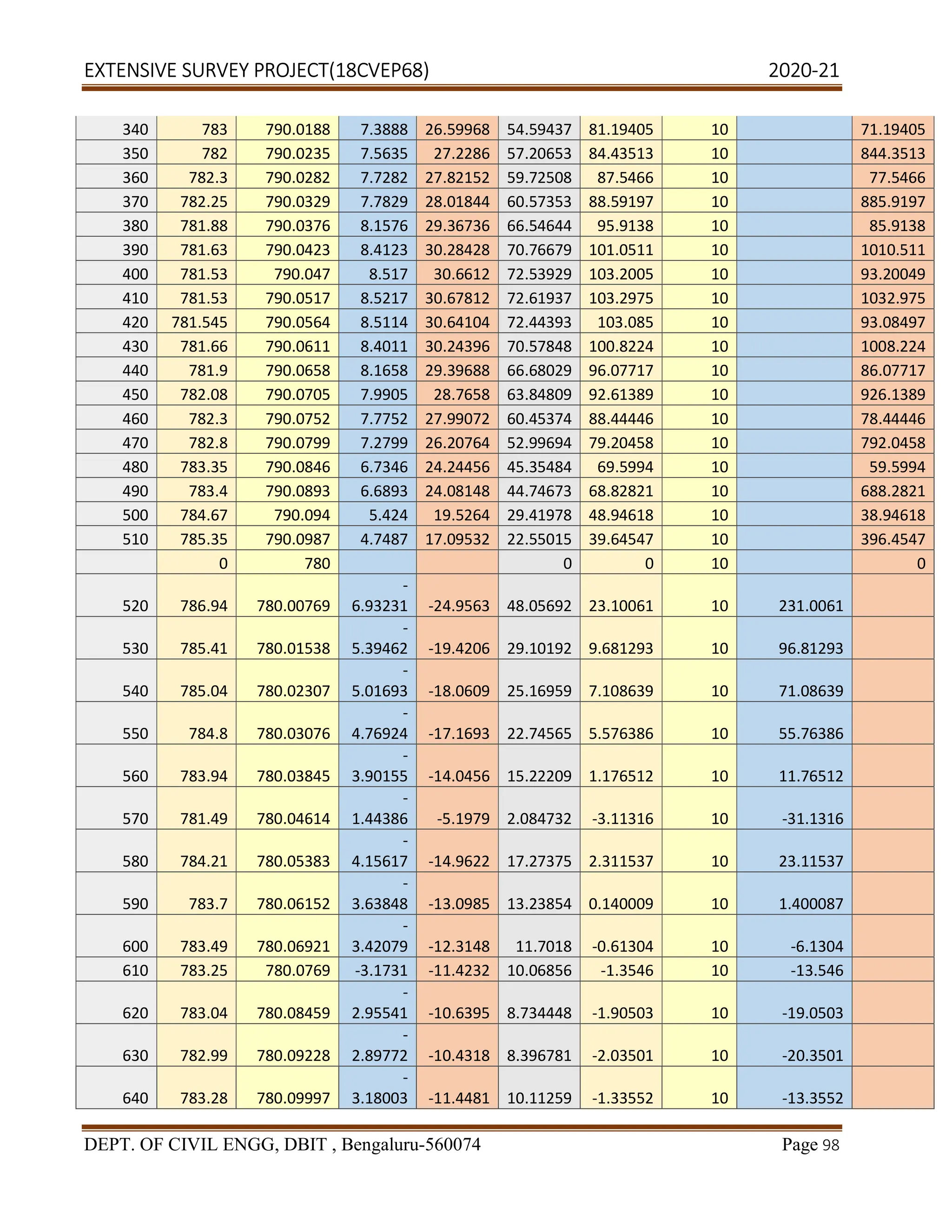
Earthwork Calculation of Canal
BED WIDTH = 2 M
SLOPE= 1:1
LENGTH 10M
CENTRAL
AREA
B*D
TOTAL
AREA
EARTH
WORK
IN
CUTTING
CHAINAGE
RL
OF
GROUND
RL
OF
FL
DEPTH
OF
CUTTING
(D)
MEAN
DEPTH
(M)
(A1)
(SD^2)
(A1+A2)
LENGTH
(L)
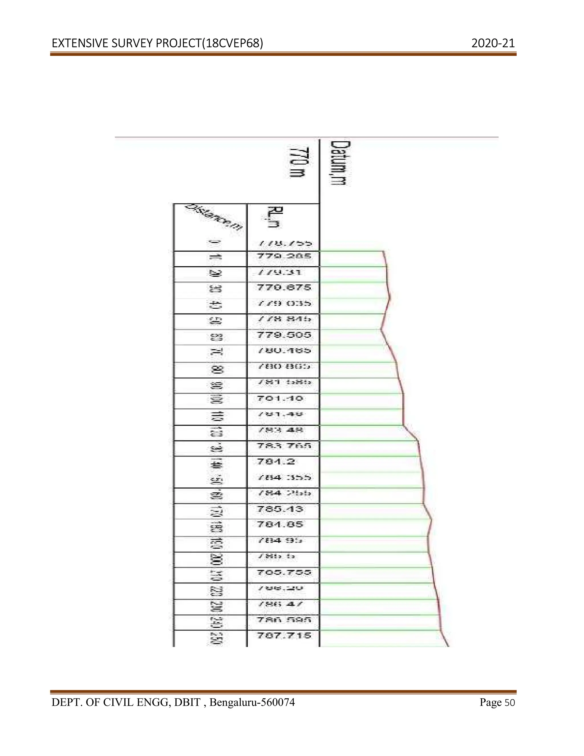
0 778.755 777 1.755
10 779.285 777.05 2.235 1.995 3.99 3.98 7.97 10 79.70025
20 779.31 777.1 2.21 2.2225 4.445 4.94 9.38 10 93.84506
30 779.675 777.15 2.525 2.3675 4.735 5.61 10.34 10 103.4006](https://image.slidesharecdn.com/2-240320174630-b4be831e/75/Extensive-survey-project-vtu-pdfproject1-39-2048.jpg)

![EXTENSIVE SURVEY PROJECT(18CVEP68) 2020-21
DEPT. OF CIVIL ENGG, DBIT , Bengaluru-560074 Page 59
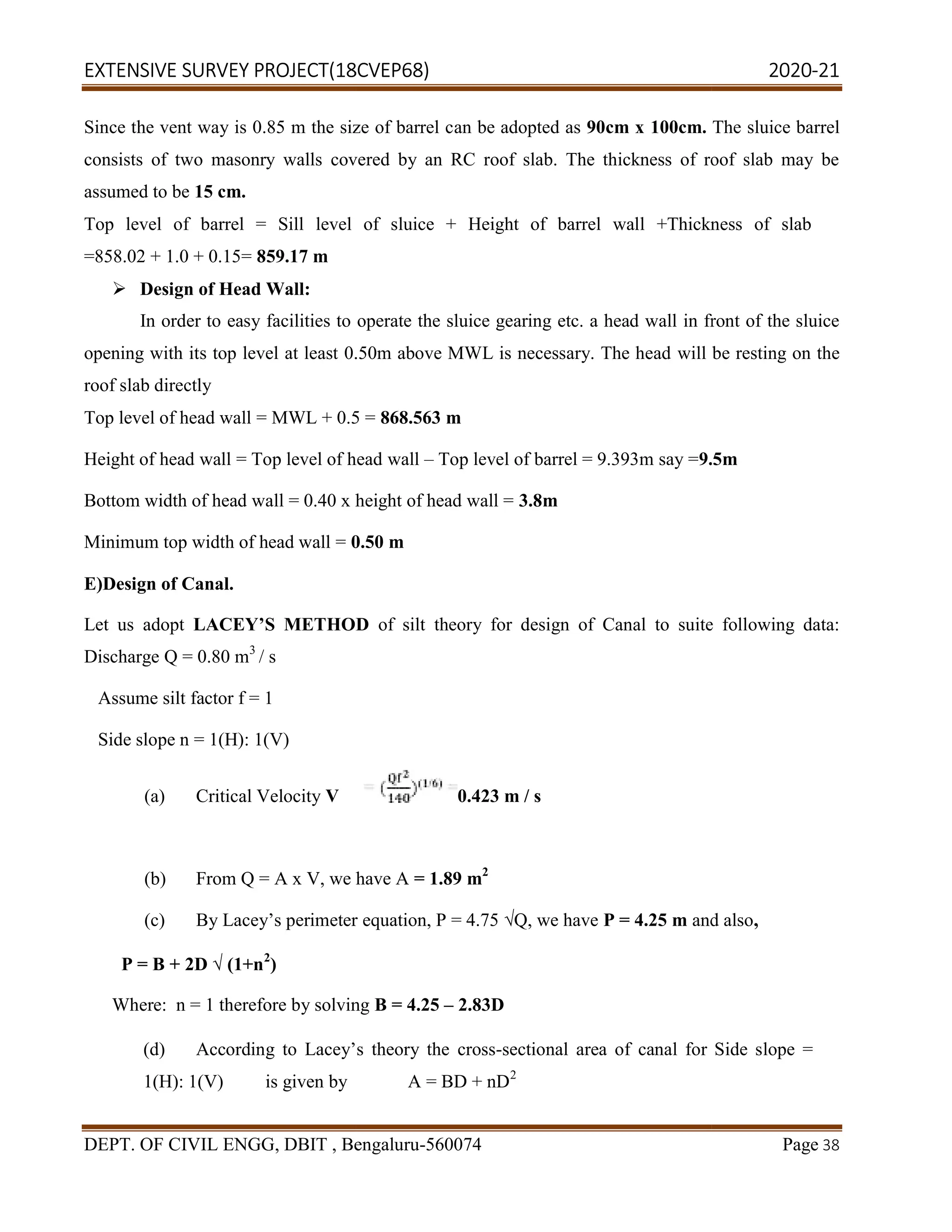
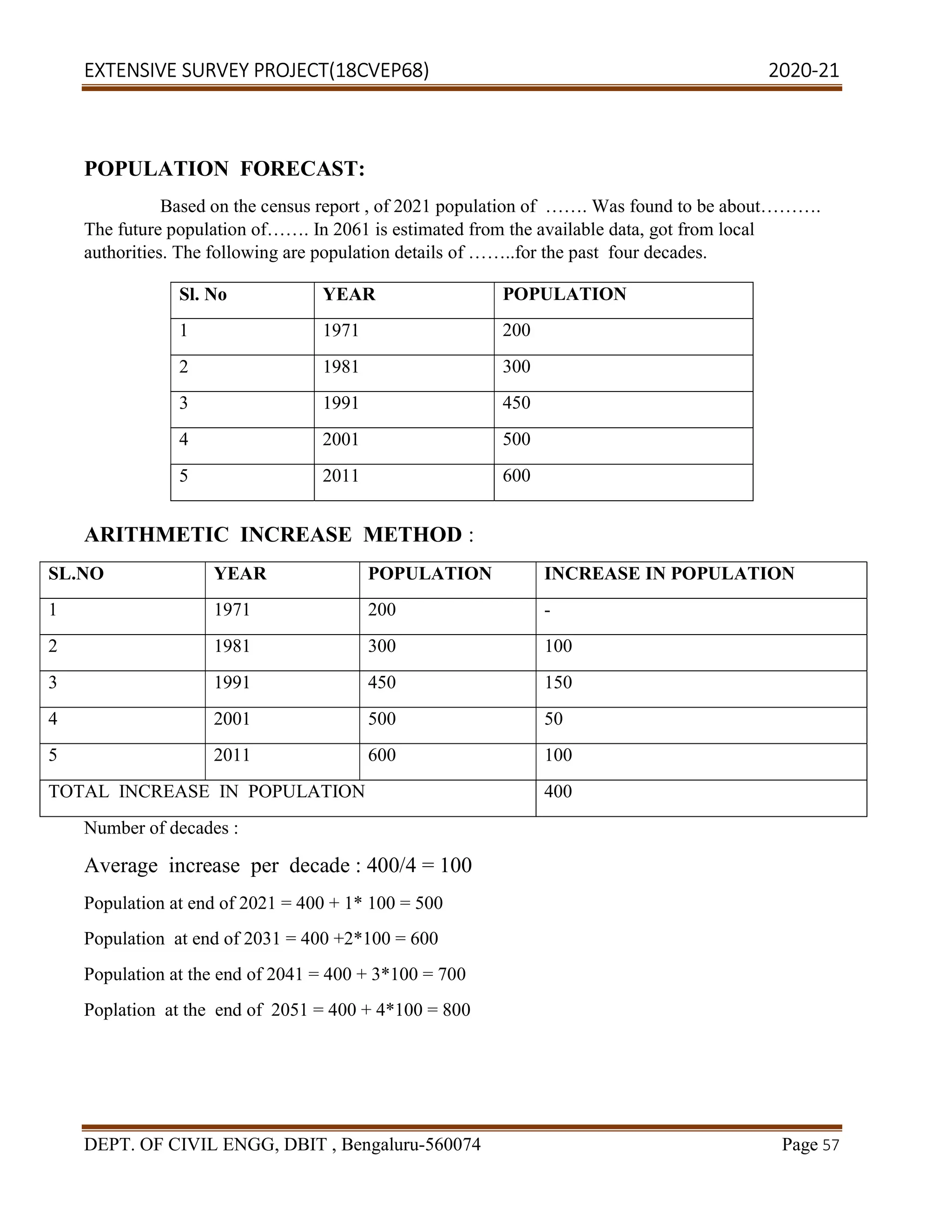
AVERAGE DECADE = 400/4 = 100
AND = 0/3 = 0
Population at end of 2021 = 600 +1× 100+(1×(1+1)/2 )×0
= 700
Population at end of 2031 = 600 + 2×100 + (2×(2+1)/2)×0
= 800
Population at end of 2041 = 600 + 3×100 + ( 3 ×(3+1)/2)×0
= 900
Population at end of 2051 = 600 + 4×100 + (4×(4+1)/2)×0
= 1000
The population of Ramohalli layout can be taken as 1000 in the year of 2051
FLOATING POPULATION :
DAILY PILGRIMS 100
MARRIAGE PARTY 5
EDUCATION CAMP 3
TOTAL 108
CATTLE POPULATION = 100 ( ASSUMED)
DESIGN OF RISING MAIN
PER CAPITA RATE OF SUPPLY
Human 130 liters/day/person
Cattle 50 liters /day/capita
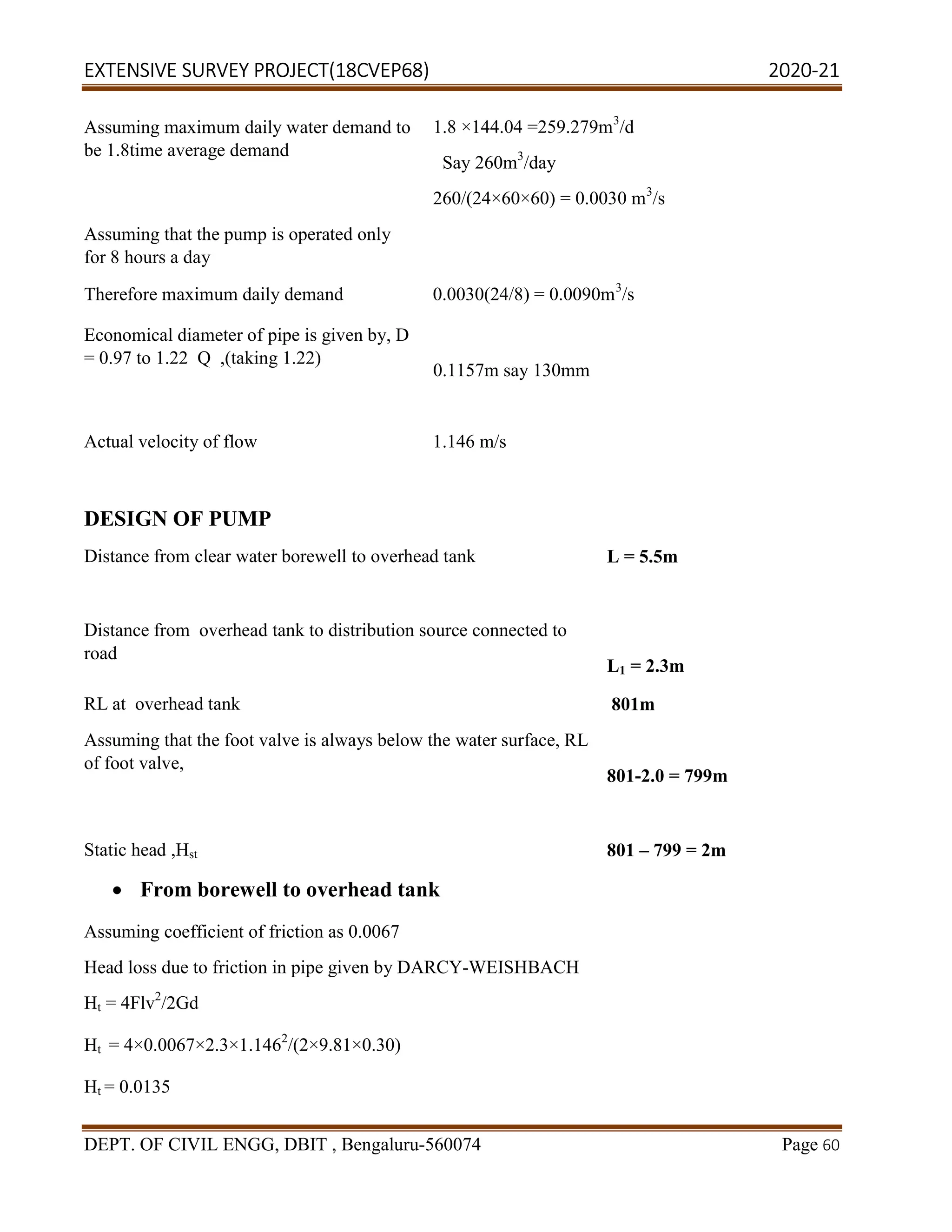
Quantity required per day
Human [1000+108] × 130 =144040
[100 × 50] 5000 liters/day
Total quantity of water 144040 liters/day (144.04m3
/day)](https://image.slidesharecdn.com/2-240320174630-b4be831e/75/Extensive-survey-project-vtu-pdfproject1-59-2048.jpg)
![EXTENSIVE SURVEY PROJECT(18CVEP68) 2020-21
DEPT. OF CIVIL ENGG, DBIT , Bengaluru-560074 Page 135
Areas of land are divided by appropriate authorities into zones within which various uses are
permitted.[4]
Thus, zoning is a technique of land-use planning as a tool of urban planning used by
local governments in most developed countries. The word is derived from the practice of designating
mapped zones which regulate the use, form, design and compatibility of development. Legally, a
zoning plan is usually enacted as a by-law with the respective procedures. In some countries, e. g.
Canada (Ontario) or Germany, zoning plans must comply with upper-tier (regional, state, provincial)
planning and policy statements.
There are a great variety of zoning types, some of which focus on regulating building form and the
relation of buildings to the street with mixed-uses, known as form-based, others with separating land
uses, known as use-based or a combination thereof.
The reasons that good land use guidance is important can include preserving property values that
might decline if someone pops an undesirable business down in the middle of a residential
neighbourhood.
The regulation of matters such as setbacks (meaning the number of feet from a street or an adjoining
property line that must be maintained free of structures) helps with a solid urban design. Two homes
inappropriately close together in a neighbourhood where there is some real room to roam around
each house would tend to detract from the neighbourhood and therefore property values.
IMPORTANCE :
Provides stability for land market by predicting future land uses
Fosters economic development
Protects aesthetic and environmental resources
Provides efficient provision of public services
Protects community character
The population is distributed throughout the town by zoning regulation so that there is no
concentration of population in any one particular zone
It prevents encroachment of one zone upon another adjacent to it
Business or commercial areas are also separately located with their garages and service stations
at a distance from the residential areas
2. Statutory Guidelines:
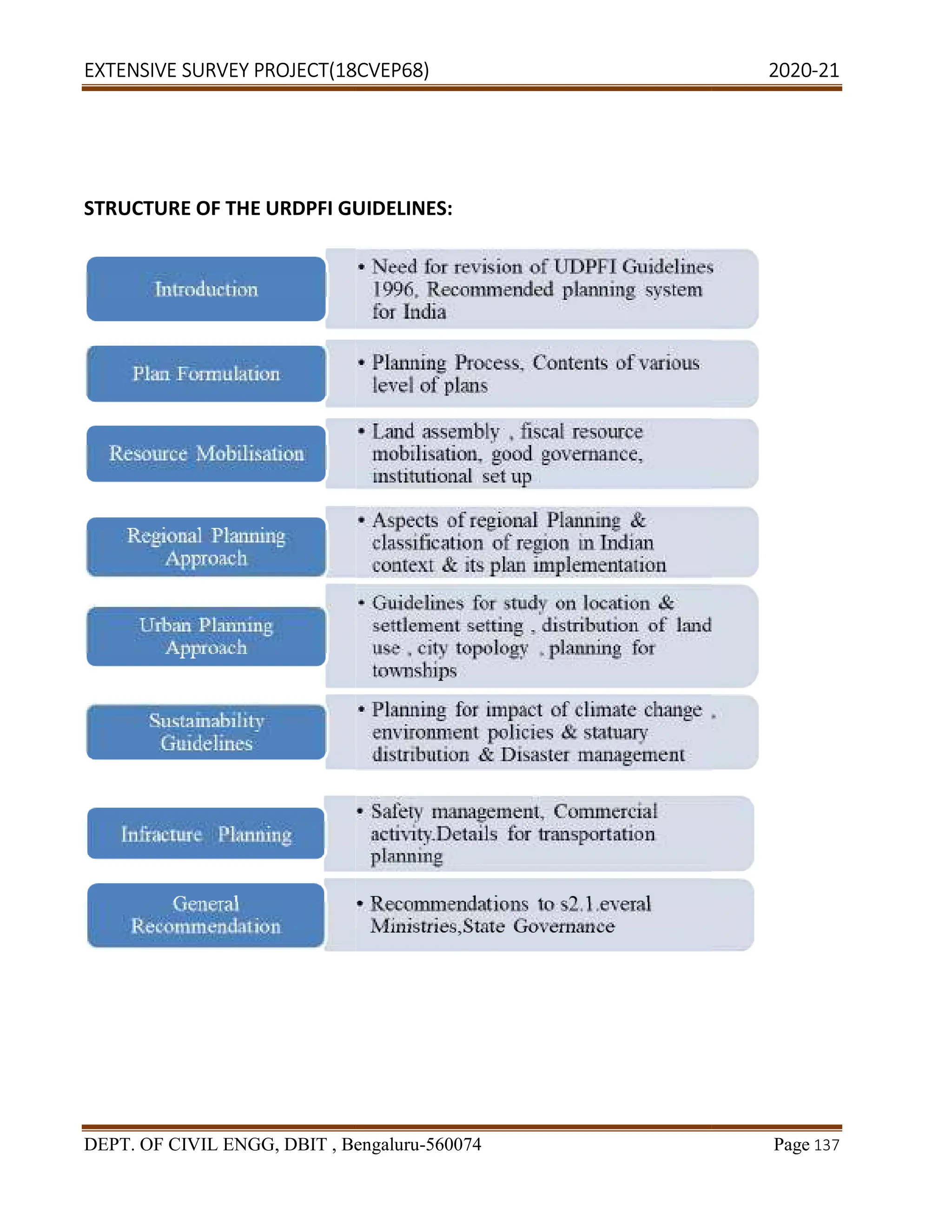
URDPFI GUIDELINES:[Urban And Rural Development Plans Formulation and
Implementation]
Introduction: The first National level planning guidelines ‘The Urban Development Plans
Formulations and Implementation Guidelines’ (UDPFI) were framed in 1996. Since then, many
changes have taken place in the field of urban development especially in view of emerging needs
and requirements of urban settlements due to rapid population growth and other reasons like
globalization and liberalization. The towns and cities have been more dynamic in nature and are
subject to unprecedented changes in terms of requirements of infrastructure and other basic services/
amenities. Besides, new emerging aspects like inclusive planning, sustainable habitat, land use and
transport integration at planning stage, preparation of Comprehensive Mobility Plans (CMP) for](https://image.slidesharecdn.com/2-240320174630-b4be831e/75/Extensive-survey-project-vtu-pdfproject1-135-2048.jpg)
![EXTENSIVE SURVEY PROJECT(18CVEP68) 2020-21
DEPT. OF CIVIL ENGG, DBIT , Bengaluru-560074 Page 139
Covered area : It is the area covered by building / buildings immediately above the plinth level
Floor area ratio(FAR) : It is the quotient obtained by dividing the total covered area of all floors
by the area of the plot. Floor area includes the mezzanine floor also.
Frontage : It is the width of the site abutting the access road
Height of Building : It is the vertical distance measured, in the case of flat roofs, from the
average level of the ground around and contiguous to the building up to the highest point of
building
High rise building or Multi-Storeyed Building : It is a building of a height of 24meters or more
above the average surrounding ground level
Licence :It is a permission or authorisation in writing by the Authority to carry out work
regulated by the bye-laws
Open space : It is an area forming an integral part of the plot, left open to sky.
BDA Master plan: [Bangalore Development Authority]
Introduction : A Master Plan is a comprehensive document which provides the broad framework
and direction for the growth and development of the city
Aim :
A Master Plan aims to integrate the various sectoral plans taking into consideration the overall
requirements in terms of land, infrastructure services, physical and social amenities,
environmental aspects etc. over a 10-20 year time frame
The plan aims to project the population, lay down the overall space, and provide direction for the
future growth and development of City keeping in view the larger perceptive
Contents :
PART 1 - Legal Provisions, Scope, Content, Limitations and FAQs
PART 2 - Extent Of Local Planning Area Op Bangalore Development Authority
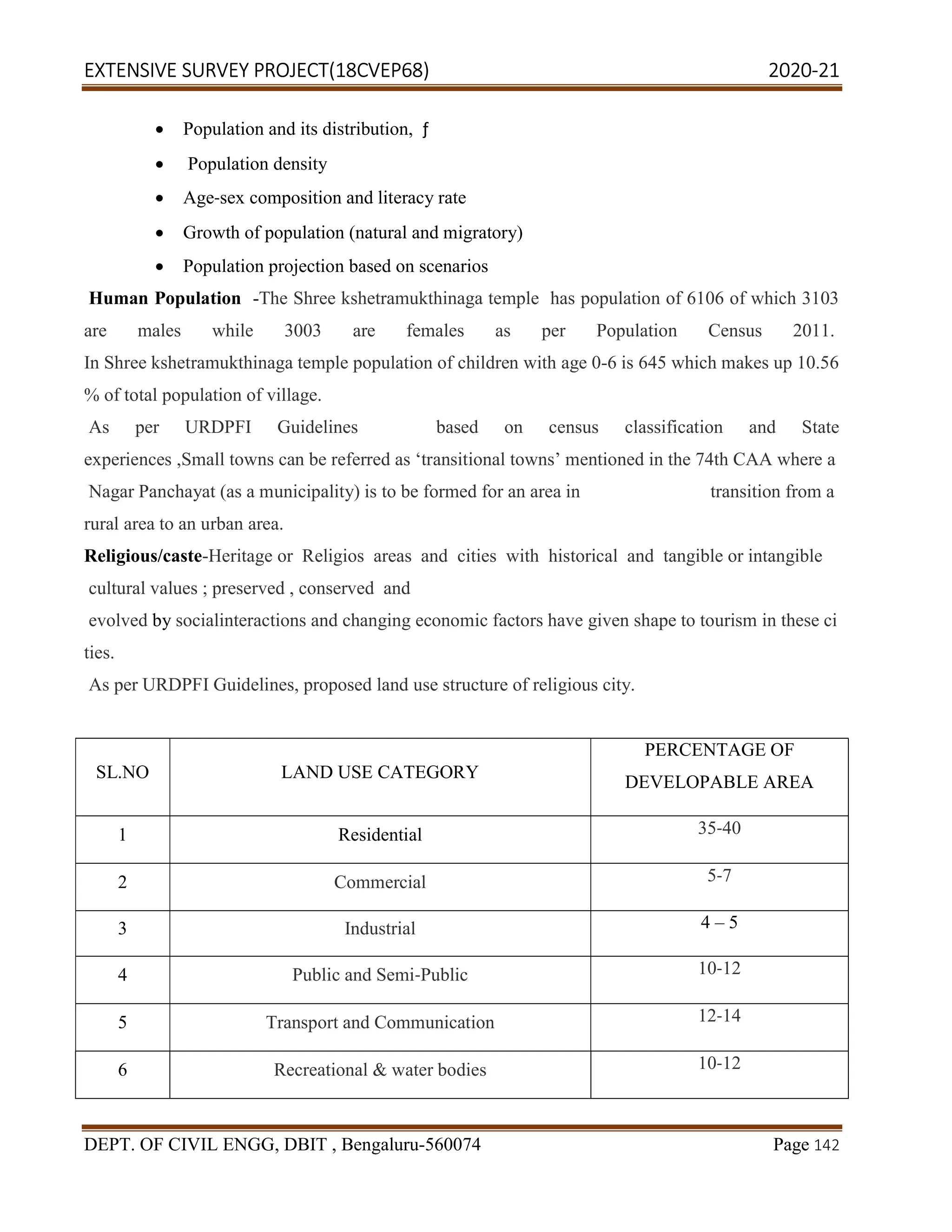
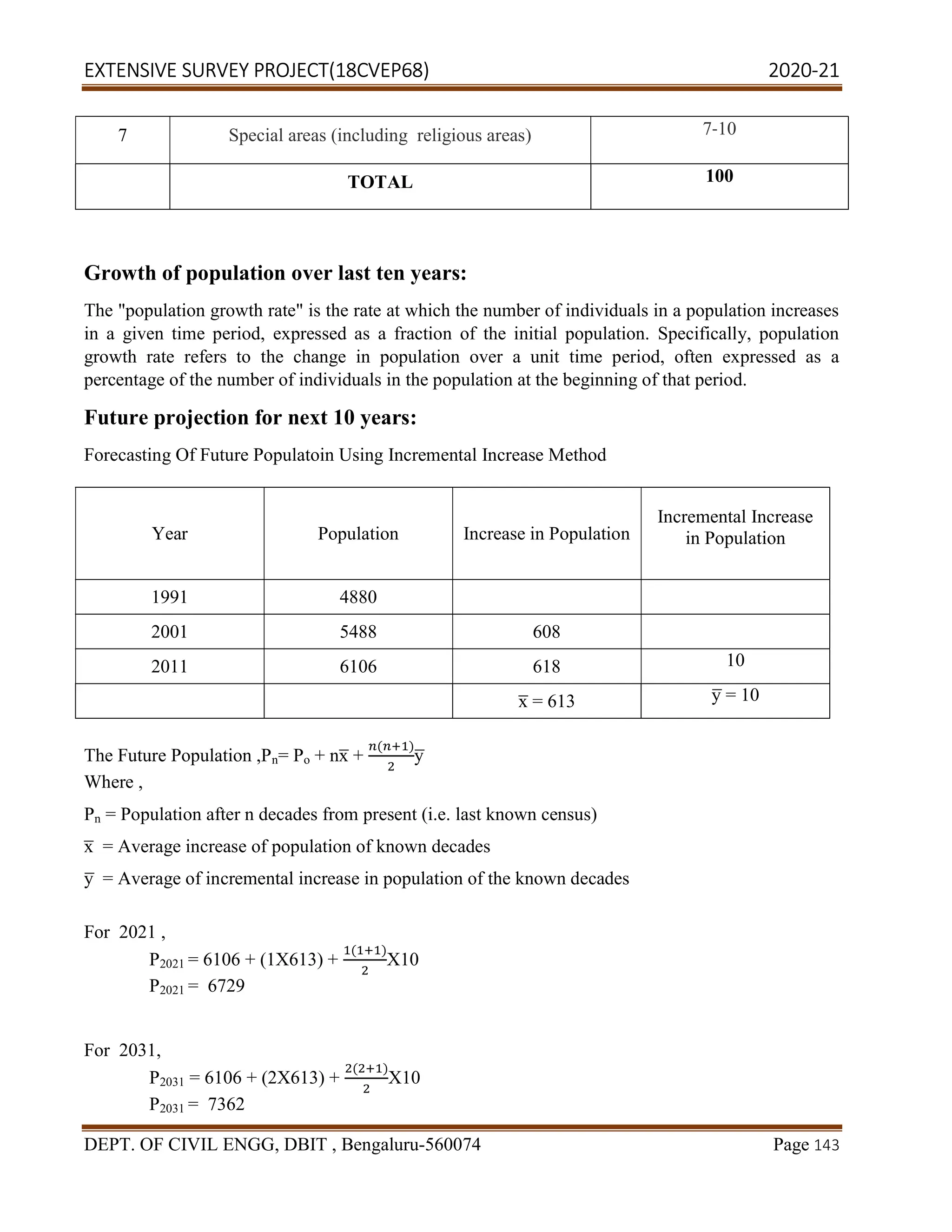
PART 3 - Population Projections
PART 4 - Rationalization Of Jurisdictions Of Planning Districts For RMP 2031
PART 5 - Transport Sector](https://image.slidesharecdn.com/2-240320174630-b4be831e/75/Extensive-survey-project-vtu-pdfproject1-139-2048.jpg)