Concrete is a composite material made of cement, sand, gravel and water. It can be classified as low, medium or high strength based on its compressive strength. Proper curing is important to achieve maximum properties. Different types of cement and reinforcement fibres are used in concrete. Concrete is susceptible to corrosion from chlorides, sulphates and carbonation which can be prevented through methods like coatings, cathodic protection and using galvanized reinforcement. Models exist to predict corrosion rates based on factors like resistivity and chloride content.


![Element [wt.%] [norm.wt.%
]
[norm.
at.%]
Compound [norm.wt.%
]
Error in
wt.% (3
Sigma)
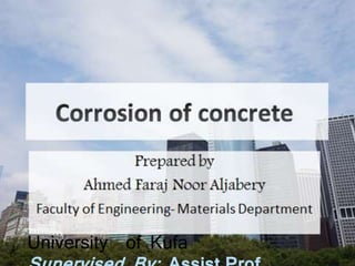
Oxygen 24.98095 20.0041 37.91945 -3.2E-16 10.55332
Silicon 1.110329 0.889122 0.960121 SiO2 1.902131 0.27504
Titanium 0 0 0 TiO2 0 0
Calcium 17.82632 14.27485 10.8022 CaO 19.97347 12.13651
Potassium 80.88574 64.7712 50.24245 K2O 78.0237 39.45965
Magnesium 0.075833 0.060725 0.075774 MgO 0.100699 0.098015
Sum: 124.8792 100 100
Table show components of concert without adding of TiO2 nanoparticles](https://image.slidesharecdn.com/concretecorrosion-170806014904/85/Concrete-corrosion-46-320.jpg)

![Element [wt.%] [norm.
wt.%]
[norm. at.%] Compound [norm.
wt.%]
Error in
wt.% (3
Sigma)
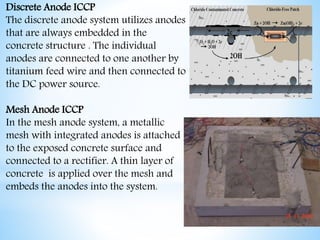
Oxygen 1.058642 20.22818 38.13122 3.05E-15 0.692535
Silicon 0.085465 1.633029 1.753636 SiO2 3.493596 0.099904
Magnesium 0.010778 0.205944 0.255554 MgO 0.341513 0.005055
Potassium 3.489825 66.68242 51.43766 K2O 80.32597 3.167678
Calcium 0.569878 10.88904 8.194291 CaO 15.23602 0.832428
Titanium 0.018913 0.361385 0.227638 TiO2 0.602904 0.063183
Sum: 5.2335 100 100
Table Shows component concert with addition](https://image.slidesharecdn.com/concretecorrosion-170806014904/85/Concrete-corrosion-48-320.jpg)


