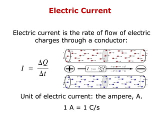
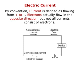
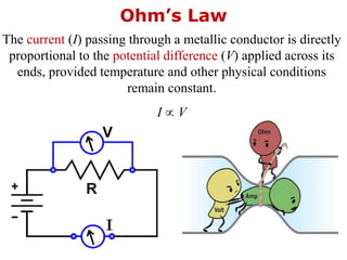
1. Electric current is the flow of electric charge through a conductor. It is measured in amperes.
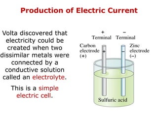
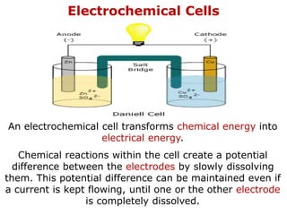
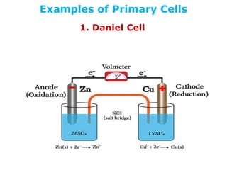
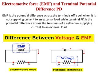
2. Electrochemical cells convert chemical energy into electrical energy through chemical reactions between electrodes, generating a potential difference.
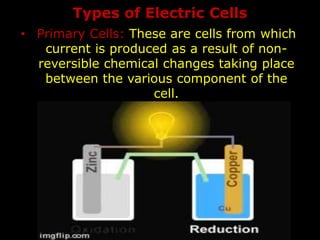
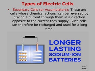
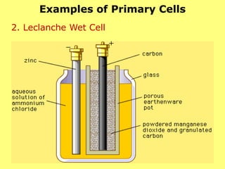
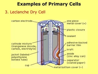
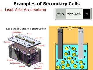
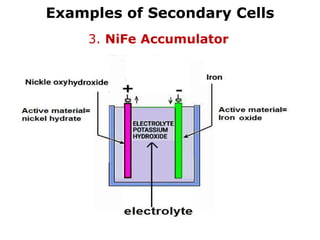
3. Primary cells produce current through irreversible chemical reactions, while secondary cells can be recharged through applying a reverse current.