This document provides an overview of key concepts related to electric circuits, including:
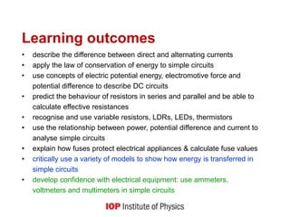
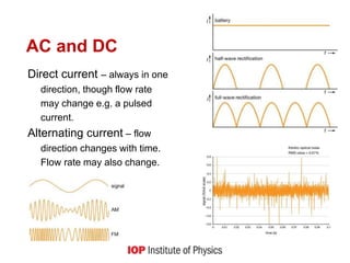
1) Describing the differences between direct and alternating currents, and discussing challenges students face distinguishing between voltage and current.
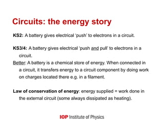
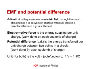
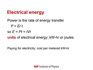
2) Explaining how batteries supply energy to a circuit by transferring energy to charges located in circuit components like filaments, in accordance with the law of conservation of energy.
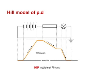
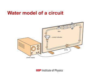
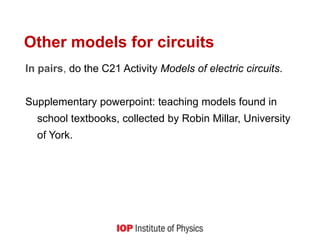
3) Discussing models used to represent circuits, including water and hill models, and how more accurate representations show batteries maintaining electric fields.
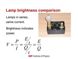
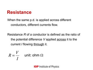
4) Defining concepts like electromotive force, potential difference, resistance, and how these relate to determining current and power in both simple and complex circuit configurations.
![Resistor networks
Resistors in series
V = V1+ V2 [conservation of energy]
IR = IR1 + IR2
R = R1 + R2 R is always larger than any of R1, R2 etc
Resistors in parallel
I = I1 + I2 [conservation of charge]
V/R = V/R1 + V/R2
1/R = 1/R1 + 1/R2 R is always smaller than any of R1, R2 etc](https://image.slidesharecdn.com/potential-diff-resistance-221115180640-efa001ee/85/Potential-diff-resistance-ppt-15-320.jpg)


![Electric current, potential difference and reietance [Autosaved] [Autosaved]....](https://cdn.slidesharecdn.com/ss_thumbnails/electriccurrentpotentialdifferenceandreietanceautosavedautosaved-230603173933-3538dcc3-thumbnail.jpg?width=640&height=640&fit=bounds)