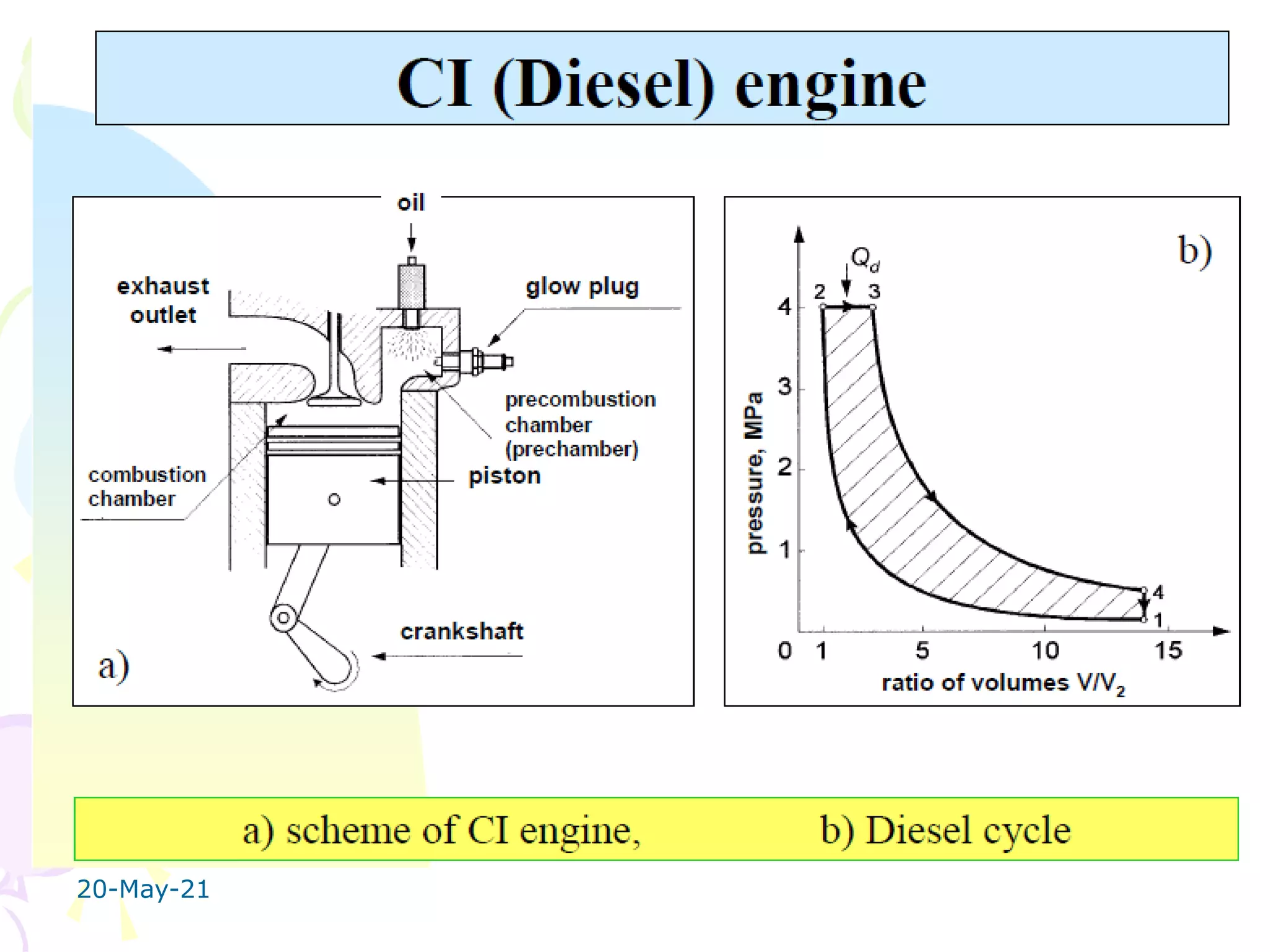
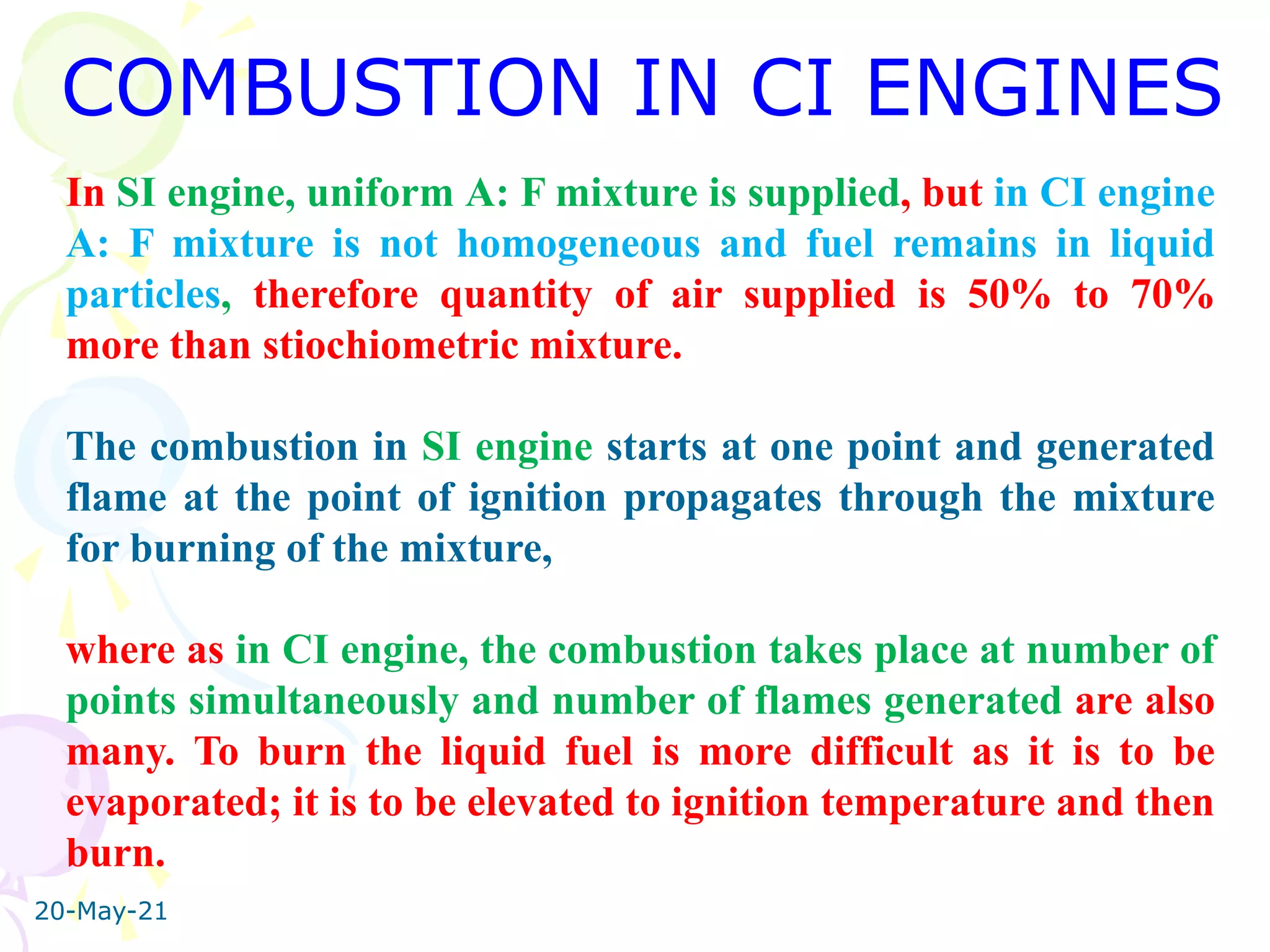
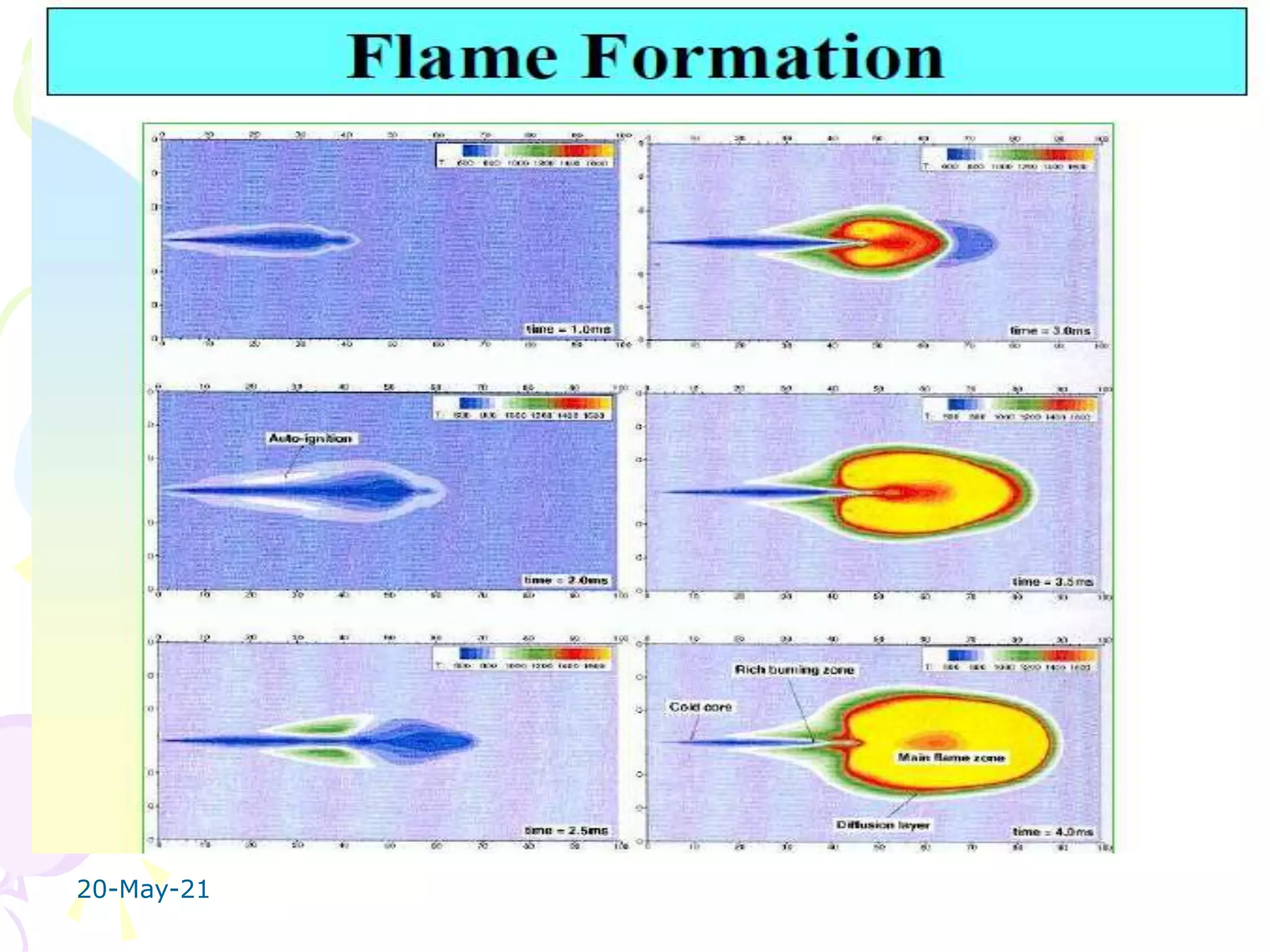
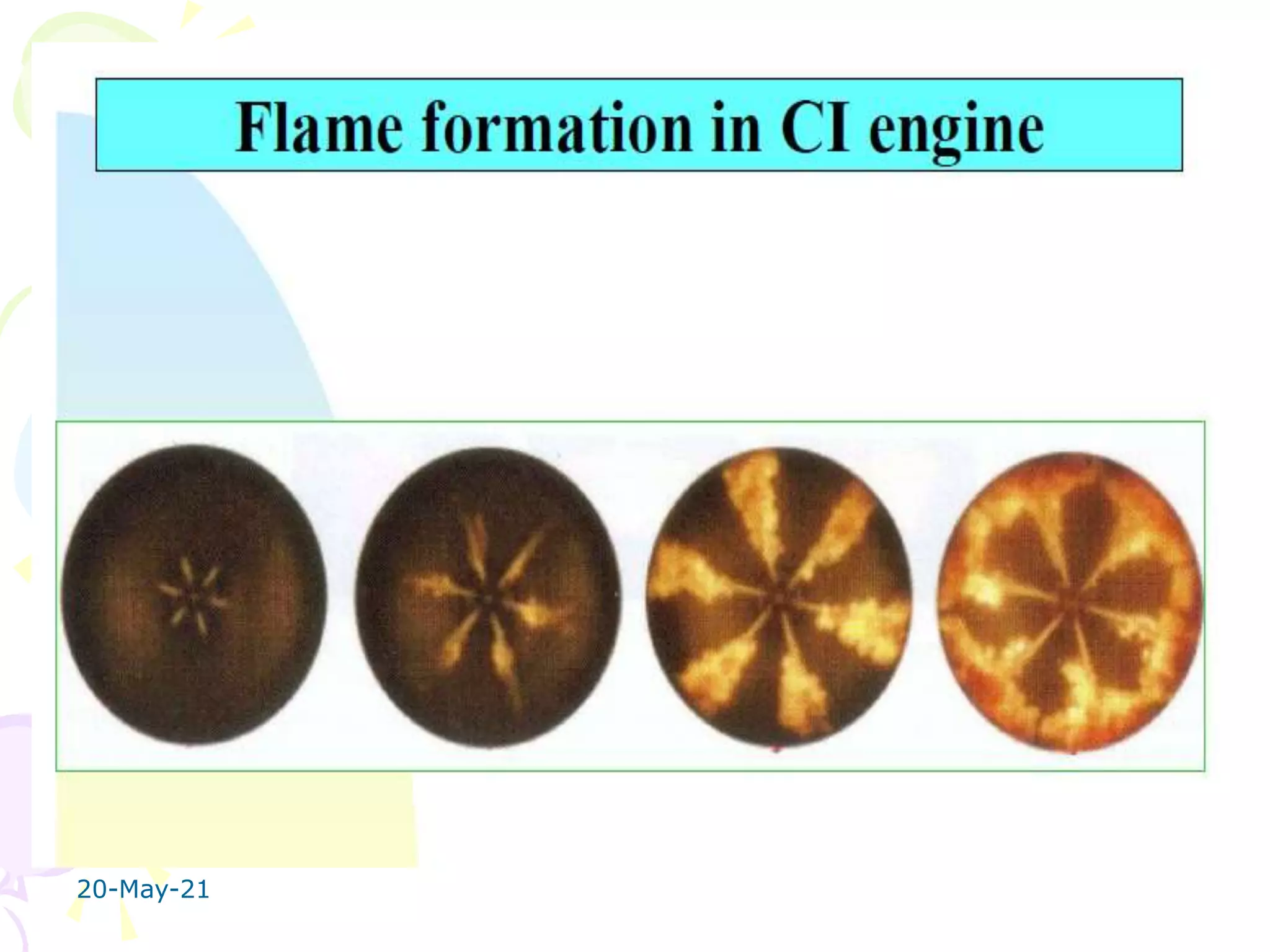
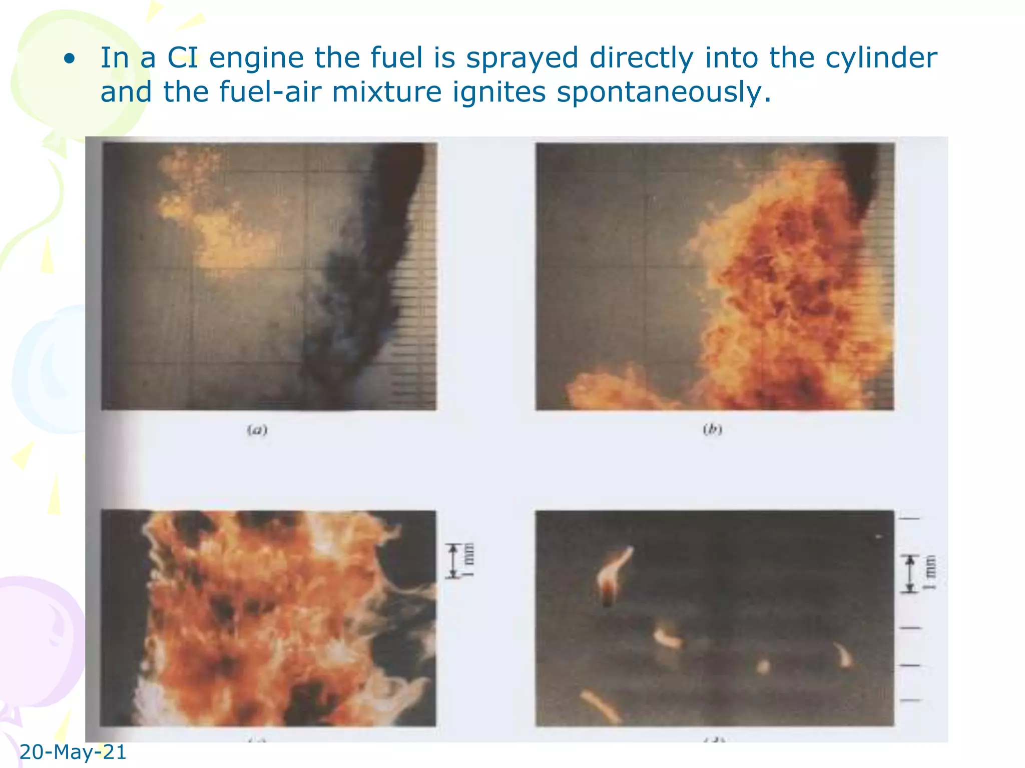
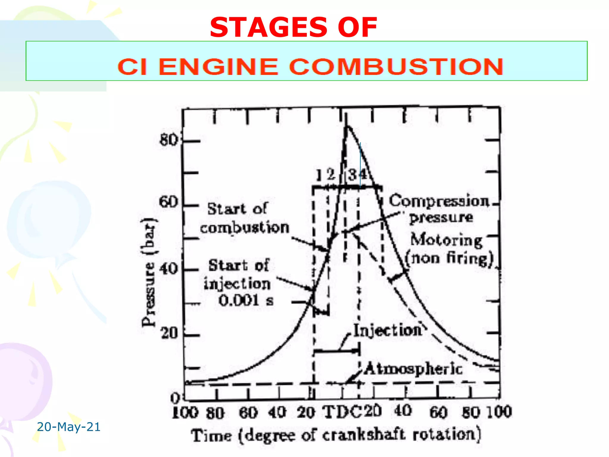
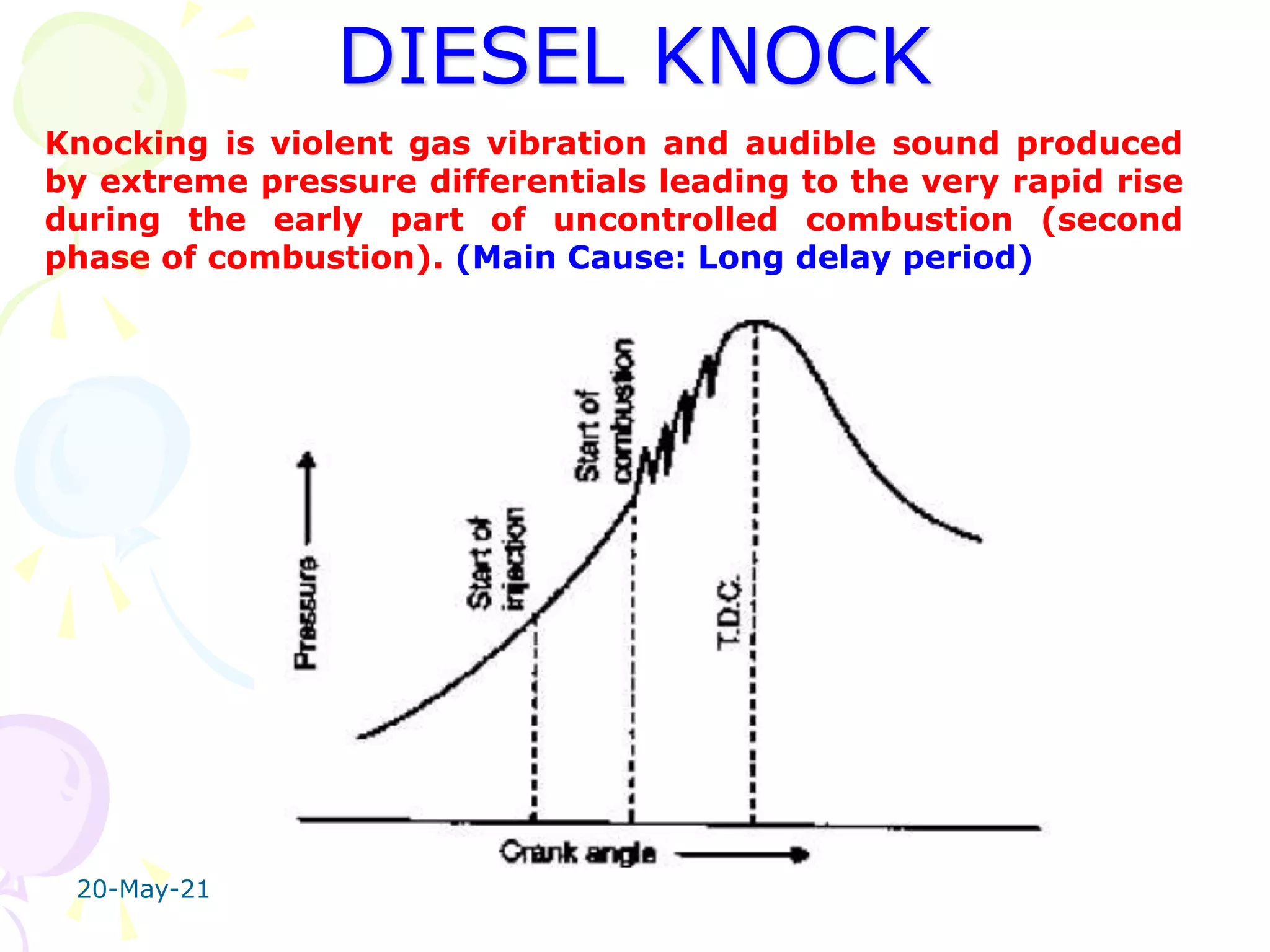
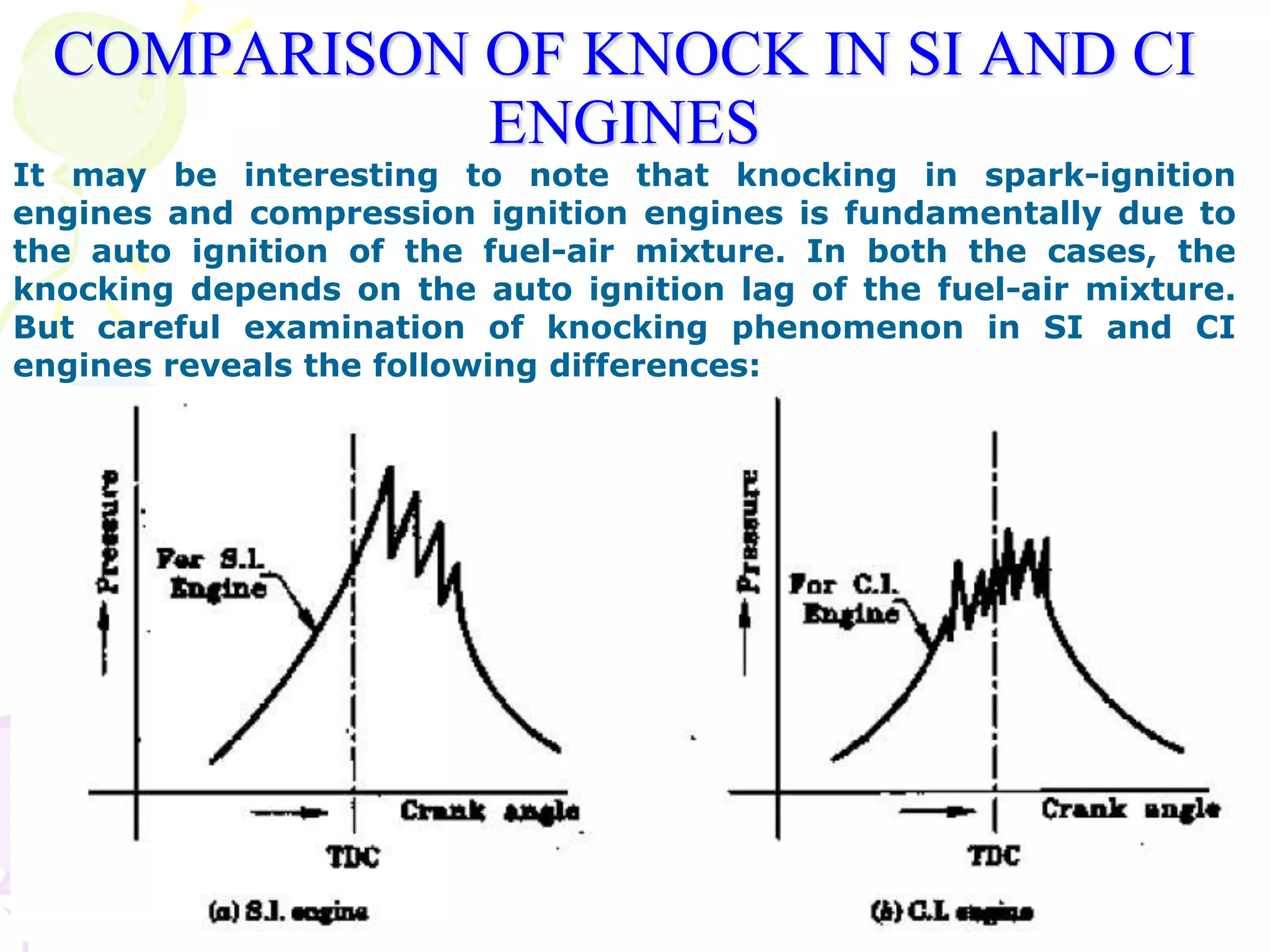
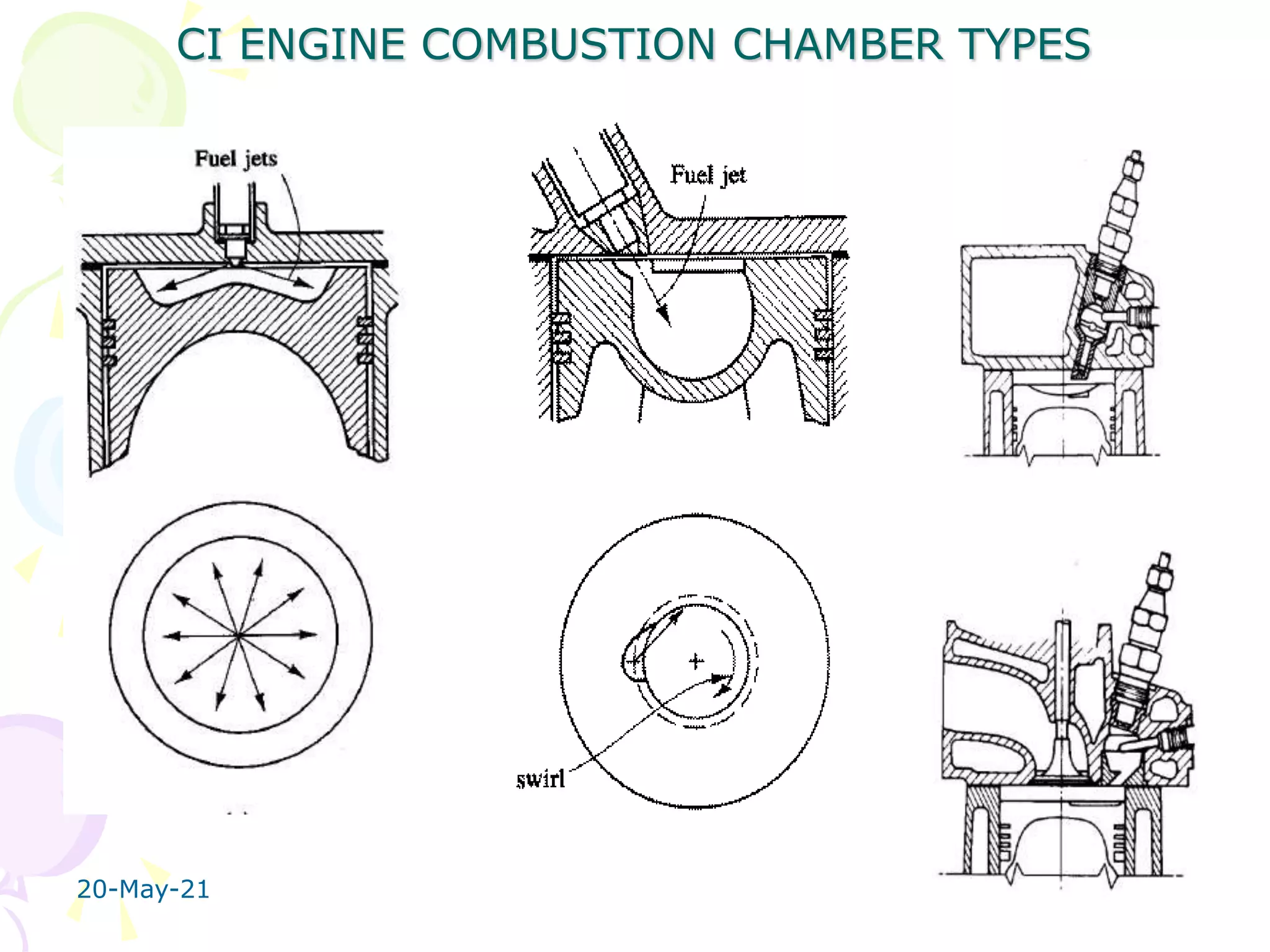
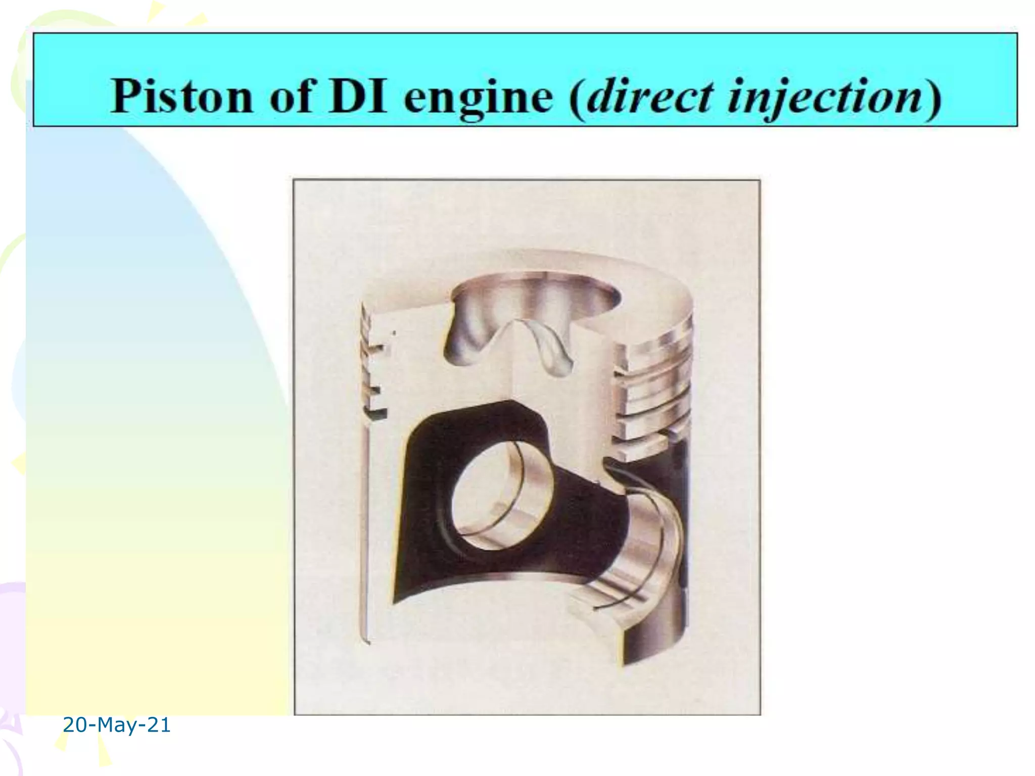
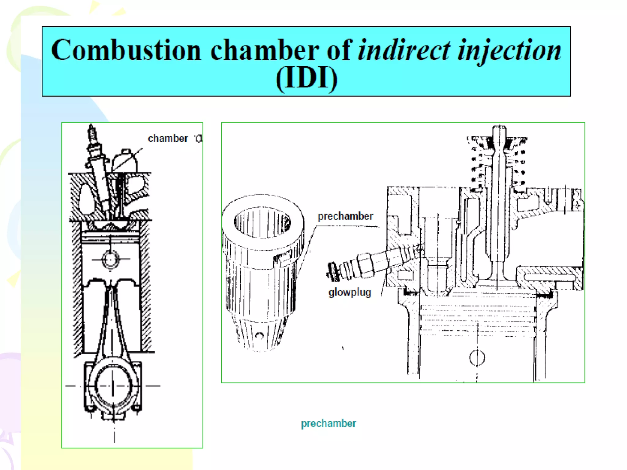
CI ENGINE COMBUSTION STAGES
UNIT-3
EME-505 I.C.ENGINES AND COMPRESSORS
B.TECH M.E 2013 BATCH
V.K.Yadav
Assistant Professor
Mechanical Engineering Department
20-May-21
20-May-21
20-May-21
COMBUSTION IN CI ENGINES
In SI engine, uniform A: F mixture is supplied, but in CI engine
A: F mixture is not homogeneous and fuel remains in liquid
particles, therefore quantity of air supplied is 50% to 70%
more than stiochiometric mixture.
The combustion in SI engine starts at one point and generated
flame at the point of ignition propagates through the mixture
for burning of the mixture,
where as in CI engine, the combustion takes place at number of
points simultaneously and number of flames generated are also
many. To burn the liquid fuel is more difficult as it is to be
evaporated; it is to be elevated to ignition temperature and then
burn.
20-May-21
20-May-21
20-May-21
Open DI
Pre IDI
• In a CI engine the fuel is sprayed directly into the cylinder
and the fuel-air mixture ignites spontaneously.
20-May-21
20-May-21
STAGES OF
CI ENGINE COMBUSTION
STAGES
20-May-21
Stage 1 : Ignition delay
Stage 2: Uncontrolled combustion
Stage 3 : Controlled Combustion
Stage 4: After Burning
20-May-21
CI ENGINE COMBUSTION STAGES Contd..
Satge.1 Ignition Delay:
The fuel does not ignite immediately upon injection into the
combustion chamber. There is a definite period of inactivity
between the time of injection and the actual burning this period
is known as the ignition delay period.
Point “a” represents the time of injection and point “b”
represents the time of combustion. The ignition delay period can
be divided into two parts, the physical delay and the chemical
delay.
The delay period in the CI engine exerts a very great influence
on both engine design and performance. It is of extreme
importance because of its effect on both the combustion rate
and knocking and also its influence on engine starting ability
and the presence of smoke in the exhaust.
20-May-21
STAGES OF COMBUSTION IN CI ENGINES
Contd..
Satge.2 Uncontrolled Combustion:
The period of rapid combustion also called the
uncontrolled combustion, is that phase in which the
pressure rise is rapid. During the delay period, a
considerable amount of fuel is accumulated in combustion
chamber, these accumulated fuel droplets burns very
rapidly causing a steep rise in pressure. The period of
rapid combustion is counted from end of delay period or
the beginning of the combustion to the point of maximum
pressure on the indicator diagram. The rate of heat-
release is maximum during this period. This is also known
as uncontrolled combustion phase, because it is difficult
to control the amount of burning / injection during the
process of burning. It may be noted that the pressure
reached during the period of rapid combustion will
depend on the duration of the delay period (the longer
the delay the more rapid and higher is the pressure rise
since more fuel would have been present in the cylinder
before the rate of burning comes under control).
STAGES OF COMBUSTION IN CI ENGINES
Contd..
Satge.3 Controlled Combustion:
The rapid combustion period is followed by the third
stage, the controlled combustion. The temperature and
pressure in the second stage are so high that fuel
droplets injected burn almost as they enter and find the
necessary oxygen and any further pressure rise can be
controlled by injection rate..
Satge.4 After Burning:
Combustion does not stop with the completion of the
injection process. The unburnt and partially burnt fuel
particles left in the combustion chamber start burning
as soon as they come into contact with the oxygen.
This process continues for a certain duration called the
after-burning period. This burning may continue in
expansion stroke up to 70 to 80% of crank travel from
TDC.
Factors affecting delay period in CI Engine
-1: Compression ratio: CR increases DP decreases
-2: Engine speed: With increase in engine speed,
the loss of heat during compression decreases,
resulting in the rise of both the temperature and pressure of
the compressed air thus reducing the delay period in
milliseconds.
-3: Output: With an increase in engine output the
air-fuel ratio decreases, operating temperatures
increase and hence delay period decreases.
-4: Injection timing: As the pressure and temperature at the
beginning of injection are lower for higher ignition advance,
the delay period increases with increase in injection advance.
The optimum angle of injection advance depends on many
factors but generally it is about 20° to 30 o before TDC.
Factors affecting delay period in CI Engine contd..
-5: Quality of the fuel
The most important property of fuel which is responsible for
chemical delay is its self ignition temperature.
Lower the self-ignition temperature, lower the delay period.
The Cetane number (CN) of the fuel is another important
parameter which is responsible for the delay period.
A fuel of higher cetane number gives lower delay period and
provides smoother engine operation.
-6: Intake temperature : Intake temperature increases DP
decreases.
-7: Intake pressure:
Increase in intake pressure or supercharging reduces the auto
ignition temperature and hence reduces the delay period.
DIESEL KNOCK
20-May-21
Knocking is violent gas vibration and audible sound produced
by extreme pressure differentials leading to the very rapid rise
during the early part of uncontrolled combustion (second
phase of combustion). (Main Cause: Long delay period)
DIESEL KNOCK Contd..
20-May-21
In C.I. engines the injection process takes place over a definite
interval of time.
Consequently, as the first few droplets injected are passing
through the ignition lag period, additional droplets are being
injected into the chamber.
If the ignition delay is longer, the actual burning
of the first few droplets is delayed and a greater quantity of
fuel droplets gets accumulated in the chamber. When the
actual burning commences, the additional fuel can cause too
rapid a rate of pressure rise.
Resulting in Jamming of forces against the piston (as if stuck
by a hammer) and rough engine operation.
20-May-21
If the ignition delay is quite long, so much fuel can
accumulate that the rate of pressure rise is almost
instantaneous.
Such, a situation produces extreme pressure differentials and
violent gas vibration known as knocking (diesel knock), and is
evidenced by audible knock
The phenomenon is similar to that in the SI engine. However,
in SI Engine knocking occurs near the end of combustion
whereas in CI engine, knocking the occurs near the beginning
of combustion.
DIESEL KNOCK Contd..
METHODS OF CONTROLING DIESEL KNOCK
1. Using a better fuel. Higher Cetane Number fuel has lower delay
period and reduces knocking tendency.
2. Controlling the Rate of Fuel Supply. By injecting less fuel in the
beginning and then more fuel amount in the combustion chamber
detonation can be controlled to a certain extent. Cam shape of
suitable profile can be designed for this purpose.
3. Knock reducing fuel injector : This type of injector avoid the
sudden increase in pressure inside the combustion chamber
because of accumulated fuel. This can be done by arranging the
injector so that only small amount of fuel is injected first. This can
be achieved by using two or more injectors arranging in out of
phase.
4. By using Ignition accelerators : C N number can be increased by
adding chemical called dopes. The two chemical dopes are used are
ethyl-nitrate and amyle –nitrate in concentration of 8.8 gm/Litre
and 7.7 gm/Litre. But these two increase the NOx emissions.
5. Increasing Swirl : Knocking can be greatly reduced by increasing
swirl ( or reducing turbulence). Swirl helps in knock free
combustion.
COMPARISON OF KNOCK IN SI AND CI
ENGINES
It may be interesting to note that knocking in spark-ignition
engines and compression ignition engines is fundamentally due to
the auto ignition of the fuel-air mixture. In both the cases, the
knocking depends on the auto ignition lag of the fuel-air mixture.
But careful examination of knocking phenomenon in SI and CI
engines reveals the following differences:
20-May-21
20-May-21
20-May-21
20-May-21
20-May-21
20-May-21
20-May-21
20-May-21
CI Engine Combustion chamber design contd..
20-May-21
CI Engine Combustion chamber design
contd..
20-May-21
Induction swirl
20-May-21
Induction swirl contd..
20-May-21
Induction swirl contd..
20-May-21
Compression swirl
20-May-21
Compression swirl contd…
Combustion swirl
20-May-21
You are able to understand now
the importance of swirl
so
Differentiate between turbulence
(SI) and Swirl (CI)
20-May-21
20-May-21
20-May-21
20-May-21
20-May-21
20-May-21
CI ENGINE COMBUSTION CHAMBER TYPES contd..
As discussed, the Two basic categories of CI engines combustion chambers
are:
i)Direct-injection (DI) –have a single open combustion chamber into which
fuel is injected directly
ii)Indirect-injection (IDI)–chamber is divided into two regions and the fuel is
injected into the “prechamber” which is connected to the main chamber via
a nozzle, or one or more orifices.
•For very-large engines (stationary power generation) which operate at low
engine speeds the time available for mixing is long so a direct injection
quiescent chamber type is used (open or shallow bowl in piston).
•As engine size decreases and engine speed increases, increasing amounts of
swirl are used to achieve fuel-air mixing (deep bowl in piston)
•For small high-speed engines used in automobiles chamber swirl is not
sufficient, indirect injection is used where high swirl or turbulence is
generated in the pre-chamber during compression and products/fuel
blowdown and mix with main chamber air
CI ENGINE COMBUSTION CHAMBER TYPES
20-May-21
20-May-21
20-May-21
20-May-21
20-May-21
20-May-21
20-May-21
20-May-21
20-May-21
20-May-21
20-May-21
20-May-21
20-May-21
20-May-21
20-May-21
20-May-21
20-May-21
20-May-21
20-May-21
20-May-21
20-May-21
20-May-21
20-May-21

CI engine combustion stages and combustion chamber design

  • 1.
    CI ENGINE COMBUSTIONSTAGES UNIT-3 EME-505 I.C.ENGINES AND COMPRESSORS B.TECH M.E 2013 BATCH V.K.Yadav Assistant Professor Mechanical Engineering Department 20-May-21
  • 2.
  • 3.
    20-May-21 COMBUSTION IN CIENGINES In SI engine, uniform A: F mixture is supplied, but in CI engine A: F mixture is not homogeneous and fuel remains in liquid particles, therefore quantity of air supplied is 50% to 70% more than stiochiometric mixture. The combustion in SI engine starts at one point and generated flame at the point of ignition propagates through the mixture for burning of the mixture, where as in CI engine, the combustion takes place at number of points simultaneously and number of flames generated are also many. To burn the liquid fuel is more difficult as it is to be evaporated; it is to be elevated to ignition temperature and then burn.
  • 4.
  • 5.
  • 6.
  • 7.
    • In aCI engine the fuel is sprayed directly into the cylinder and the fuel-air mixture ignites spontaneously. 20-May-21
  • 8.
  • 9.
    CI ENGINE COMBUSTION STAGES 20-May-21 Stage1 : Ignition delay Stage 2: Uncontrolled combustion Stage 3 : Controlled Combustion Stage 4: After Burning
  • 10.
    20-May-21 CI ENGINE COMBUSTIONSTAGES Contd.. Satge.1 Ignition Delay: The fuel does not ignite immediately upon injection into the combustion chamber. There is a definite period of inactivity between the time of injection and the actual burning this period is known as the ignition delay period. Point “a” represents the time of injection and point “b” represents the time of combustion. The ignition delay period can be divided into two parts, the physical delay and the chemical delay. The delay period in the CI engine exerts a very great influence on both engine design and performance. It is of extreme importance because of its effect on both the combustion rate and knocking and also its influence on engine starting ability and the presence of smoke in the exhaust.
  • 11.
  • 12.
    STAGES OF COMBUSTIONIN CI ENGINES Contd.. Satge.2 Uncontrolled Combustion: The period of rapid combustion also called the uncontrolled combustion, is that phase in which the pressure rise is rapid. During the delay period, a considerable amount of fuel is accumulated in combustion chamber, these accumulated fuel droplets burns very rapidly causing a steep rise in pressure. The period of rapid combustion is counted from end of delay period or the beginning of the combustion to the point of maximum pressure on the indicator diagram. The rate of heat- release is maximum during this period. This is also known as uncontrolled combustion phase, because it is difficult to control the amount of burning / injection during the process of burning. It may be noted that the pressure reached during the period of rapid combustion will depend on the duration of the delay period (the longer the delay the more rapid and higher is the pressure rise since more fuel would have been present in the cylinder before the rate of burning comes under control).
  • 13.
    STAGES OF COMBUSTIONIN CI ENGINES Contd.. Satge.3 Controlled Combustion: The rapid combustion period is followed by the third stage, the controlled combustion. The temperature and pressure in the second stage are so high that fuel droplets injected burn almost as they enter and find the necessary oxygen and any further pressure rise can be controlled by injection rate.. Satge.4 After Burning: Combustion does not stop with the completion of the injection process. The unburnt and partially burnt fuel particles left in the combustion chamber start burning as soon as they come into contact with the oxygen. This process continues for a certain duration called the after-burning period. This burning may continue in expansion stroke up to 70 to 80% of crank travel from TDC.
  • 14.
    Factors affecting delayperiod in CI Engine -1: Compression ratio: CR increases DP decreases -2: Engine speed: With increase in engine speed, the loss of heat during compression decreases, resulting in the rise of both the temperature and pressure of the compressed air thus reducing the delay period in milliseconds. -3: Output: With an increase in engine output the air-fuel ratio decreases, operating temperatures increase and hence delay period decreases. -4: Injection timing: As the pressure and temperature at the beginning of injection are lower for higher ignition advance, the delay period increases with increase in injection advance. The optimum angle of injection advance depends on many factors but generally it is about 20° to 30 o before TDC.
  • 15.
    Factors affecting delayperiod in CI Engine contd.. -5: Quality of the fuel The most important property of fuel which is responsible for chemical delay is its self ignition temperature. Lower the self-ignition temperature, lower the delay period. The Cetane number (CN) of the fuel is another important parameter which is responsible for the delay period. A fuel of higher cetane number gives lower delay period and provides smoother engine operation. -6: Intake temperature : Intake temperature increases DP decreases. -7: Intake pressure: Increase in intake pressure or supercharging reduces the auto ignition temperature and hence reduces the delay period.
  • 16.
    DIESEL KNOCK 20-May-21 Knocking isviolent gas vibration and audible sound produced by extreme pressure differentials leading to the very rapid rise during the early part of uncontrolled combustion (second phase of combustion). (Main Cause: Long delay period)
  • 17.
    DIESEL KNOCK Contd.. 20-May-21 InC.I. engines the injection process takes place over a definite interval of time. Consequently, as the first few droplets injected are passing through the ignition lag period, additional droplets are being injected into the chamber. If the ignition delay is longer, the actual burning of the first few droplets is delayed and a greater quantity of fuel droplets gets accumulated in the chamber. When the actual burning commences, the additional fuel can cause too rapid a rate of pressure rise. Resulting in Jamming of forces against the piston (as if stuck by a hammer) and rough engine operation.
  • 18.
    20-May-21 If the ignitiondelay is quite long, so much fuel can accumulate that the rate of pressure rise is almost instantaneous. Such, a situation produces extreme pressure differentials and violent gas vibration known as knocking (diesel knock), and is evidenced by audible knock The phenomenon is similar to that in the SI engine. However, in SI Engine knocking occurs near the end of combustion whereas in CI engine, knocking the occurs near the beginning of combustion. DIESEL KNOCK Contd..
  • 19.
    METHODS OF CONTROLINGDIESEL KNOCK 1. Using a better fuel. Higher Cetane Number fuel has lower delay period and reduces knocking tendency. 2. Controlling the Rate of Fuel Supply. By injecting less fuel in the beginning and then more fuel amount in the combustion chamber detonation can be controlled to a certain extent. Cam shape of suitable profile can be designed for this purpose. 3. Knock reducing fuel injector : This type of injector avoid the sudden increase in pressure inside the combustion chamber because of accumulated fuel. This can be done by arranging the injector so that only small amount of fuel is injected first. This can be achieved by using two or more injectors arranging in out of phase. 4. By using Ignition accelerators : C N number can be increased by adding chemical called dopes. The two chemical dopes are used are ethyl-nitrate and amyle –nitrate in concentration of 8.8 gm/Litre and 7.7 gm/Litre. But these two increase the NOx emissions. 5. Increasing Swirl : Knocking can be greatly reduced by increasing swirl ( or reducing turbulence). Swirl helps in knock free combustion.
  • 20.
    COMPARISON OF KNOCKIN SI AND CI ENGINES It may be interesting to note that knocking in spark-ignition engines and compression ignition engines is fundamentally due to the auto ignition of the fuel-air mixture. In both the cases, the knocking depends on the auto ignition lag of the fuel-air mixture. But careful examination of knocking phenomenon in SI and CI engines reveals the following differences:
  • 21.
  • 22.
  • 23.
  • 24.
  • 25.
  • 26.
  • 27.
  • 28.
  • 29.
    CI Engine Combustionchamber design contd..
  • 30.
  • 31.
    CI Engine Combustionchamber design contd.. 20-May-21 Induction swirl
  • 32.
  • 33.
  • 34.
  • 35.
  • 36.
  • 37.
    You are ableto understand now the importance of swirl so Differentiate between turbulence (SI) and Swirl (CI) 20-May-21
  • 38.
  • 39.
  • 40.
  • 41.
  • 42.
  • 43.
    CI ENGINE COMBUSTIONCHAMBER TYPES contd.. As discussed, the Two basic categories of CI engines combustion chambers are: i)Direct-injection (DI) –have a single open combustion chamber into which fuel is injected directly ii)Indirect-injection (IDI)–chamber is divided into two regions and the fuel is injected into the “prechamber” which is connected to the main chamber via a nozzle, or one or more orifices. •For very-large engines (stationary power generation) which operate at low engine speeds the time available for mixing is long so a direct injection quiescent chamber type is used (open or shallow bowl in piston). •As engine size decreases and engine speed increases, increasing amounts of swirl are used to achieve fuel-air mixing (deep bowl in piston) •For small high-speed engines used in automobiles chamber swirl is not sufficient, indirect injection is used where high swirl or turbulence is generated in the pre-chamber during compression and products/fuel blowdown and mix with main chamber air
  • 44.
    CI ENGINE COMBUSTIONCHAMBER TYPES 20-May-21
  • 45.
  • 46.
  • 47.
  • 48.
  • 49.
  • 50.
  • 51.
  • 52.
  • 53.
  • 54.
  • 55.
  • 56.
  • 57.
  • 58.
  • 59.
  • 60.
  • 61.
  • 62.
  • 63.
  • 64.
  • 65.
  • 66.