The document discusses the development of a controller for a Static Synchronous Series Compensator (SSSC) which regulates real and reactive power flow in AC transmission lines. It explains how SSSC, a solid-state voltage source inverter connected in series with the transmission line, can emulate variable capacitive and inductive reactance to enhance power transmission efficiency. Additionally, it covers conventional control methods and introduces the concept of Flexible AC Transmission Systems (FACTS) that utilize such controllers for better management of power flow in transmission networks.
![International Journal of Power Electronics and Drive System (IJPEDS)
Vol. 4, No. 1, March 2014 pp. 127~136
ISSN: 2088-8694 127
Journal homepage: http://iaesjournal.com/online/index.php/IJPEDS
Evolve the Controller for Static Synchronous Series
Compensator Based on Control Strategy of Sen Transformer
Raju J*, Kowslaya M**
* School of Electrical Engineering, VIT University
** School of Electrical Engineering, VIT University
Article Info ABSTRACT
Article history:
Received Nov 29, 2013
Revised Jan 23, 2014
Accepted Feb 14, 2014
Real and Reactive power flow in an alternating current transmission line can
be independently controlled by connecting, to the transmission line, a series-
compensating voltage, which is variable in magnitude and phase angle. The
Static Synchronous Series Compensator (SSSC), a solid-state voltage source
inverter (VSC) coupled with a transformer, is connected in series with a
transmission line. An SSSC injects an almost sinusoidal voltage, of variable
magnitude, in series with a transmission line. This injected voltage is almost
in quadrature with the line current, thereby emulating an inductive or a
capacitive reactance in series with the transmission line. This emulated
variable reactance, inserted by the injected voltage source, influences the
electric power flow in the transmission line. In this report, an attempt is made
to evolve the model of SSSC and VSC with preliminary studies for the
controller design.
Keyword:
FACTS
Reactive Power
SEN Transformer
SSSC
VSC
Copyright © 2014 Institute of Advanced Engineering and Science.
All rights reserved.
Corresponding Author:
Raju J
School of Electrical Engineering
VIT University
Vellore-632014, Tamilnadu, India
Email: jraju@vit.ac.in
1. INTRODUCTION
1.1. Electrical Transmission Networks
An electrical power transmission network comprises mostly three-phase alternating-current (ac)
transmission lines operating at different transmission voltages. With increasing requirement of power-
transmission capacity and / or longer transmission distances, the transmission voltages continue to increase;
indeed, increases in transmission voltages are linked closely to decreasing transmission losses.
1.2. Conventional Control Methods
The following conventional control methods are used to control the power flow in transmission line
network
Introducing the series capacitor in transmission line to control the line impedance.
Control of bus voltage by using Automatic generation control (AGC) / Transformer tap changer
Controlling the phase angle by using Phase-shifting transformers
1.3. Flexible AC Transmission System
Flexible AC Transmission System (FACTS) is a concept based on power-electronic controllers,
which enhance the value of transmission networks by increasing the use of their capacity. As these
controllers operate very fast, they enlarge the safe operating limits of a transmission system without risking
stability [1], [2].](https://image.slidesharecdn.com/1218dec135246evolvethecontrollerforsssc-171212151932/75/Evolve-the-Controller-for-Static-Synchronous-Series-Compensator-Based-on-Control-Strategy-of-Sen-Transformer-1-2048.jpg)
![ ISSN: 2088-8694
IJPEDS Vol. 4, No. 1, March 2014 : 127 – 136
128
Today, it is expected that within the operating constraints of the current-carrying thermal limits of
conductor, the voltage limits of electrical insulating devices, and the structural limits of the supporting
infrastructure, an operator should be able to control power flows on lines to secure the highest safety margin
as well as transmit electrical power at a minimum of operating cost.
In general, FACTS devices possess the following technological attributes [3]:
Provide dynamic reactive power support and voltage control.
Reduce the need for construction of new transmission lines, capacitors, reactors, etc which,
– Mitigate environmental and regulatory concerns.
– Improve aesthetics by reducing the need for construction of new facilities such as
transmission lines.
Improve system stability.
Control real and reactive power flow.
The following FACTS controllers are used to control the power flow in transmission line network
Thyristor-Switched Series Capacitor (TSSC)
Thyristor-Controlled Series Capacitor (TCSC)
Thyristor-Controlled Phase Angle Regulator (PAR)
Static Synchronous Series Compensator (SSSC)
The Static Synchronous Series Compensator is one of the most recent FACTS devices for power
transmission line series compensation. The operation and control fundamentals of the SSSC can be found in
[1], [4], [5].
1.4. Static Synchronous Series Compensation (SSSC)
Figure 1. Basic Building block of SSSC
The basic building block of the SSSC as shown Figure 1 is a dc-ac converter which is connected in
series with the transmission line by a coupling transformer. This injected voltage is almost in quadrature with
the line current. A small part of the injected voltage which is in phase with the line voltage which is in
quadrature with the line current emulates an inductive or a capacitive reactance in series with the
transmission line. This emulated variable reactance, inserted by the injected voltage source, influences the
electric power flow in the transmission line.
An impedance compensation controller can compensate for the transmission line resistance if an
SSSC is operated with an energy storage system. An impedance compensation controller, when used with an
SSSC and no energy storage system, is essentially a reactance compensation controller.
2. SEN TRANSFORMER AS FACTS CONTROLLER
A review of operating principle of SEN Transformer is carried out as given below.](https://image.slidesharecdn.com/1218dec135246evolvethecontrollerforsssc-171212151932/75/Evolve-the-Controller-for-Static-Synchronous-Series-Compensator-Based-on-Control-Strategy-of-Sen-Transformer-2-2048.jpg)
![IJPEDS ISSN: 2088-8694
Evolve the Controller for Static Synchronous Series Compensator Based on Control Strategy of … (Raju J)
129
2.1. Direct Method of Voltage Regulation
In order to regulate the voltage at any point in a transmission line, an in-phase or an out-of-phase
voltage is connected in series with the line [6]. Figure 2(a) shows a voltage regulator scheme for regulating
the voltage at any point in a transmission line. The exciter unit consists of a three-phase Y connected primary
winding, which is impressed with the line voltage, Vs. The voltage-regulating unit consists of a total of six
secondary windings (two windings in each phase for a bipolar voltage connection). The line is regulated at a
voltage, Vs’, by adding a compensating voltage, Vs’s, either in- or out of phase with the line voltage, Vs. The
corresponding phasor diagram is shown in Figure 2(b).
Figure 2. (a) Voltage regulator circuit (b) phasor diagram
The bipolar compensating voltage in any phase is induced, through autotransformer action, in two
windings placed on the same phase of the transformer core.
2.2. Phase Angle Regulation
A Phase Angle Regulator (PAR) connects a voltage in series with the transmission line and in
quadrature with the phase-to neutral voltage of the transmission line as shown in Figure 3(a). The series-
connected compensating voltage introduces a phase shift, , [Figure 3(b)] whose magnitude (for small
change) in radian varies with the magnitude of the compensating voltage in p.u where the phase-to-neutral
voltage of the transmission line is the base voltage [6].
Figure 3. (a) Phase angle regulator circuit (b) phasor diagram](https://image.slidesharecdn.com/1218dec135246evolvethecontrollerforsssc-171212151932/75/Evolve-the-Controller-for-Static-Synchronous-Series-Compensator-Based-on-Control-Strategy-of-Sen-Transformer-3-2048.jpg)
![ ISSN: 2088-8694
IJPEDS Vol. 4, No. 1, March 2014 : 127 – 136
130
In a typical configuration, a PAR consists of two transformers as shown in Figure 3(a). The first
transformer (exciter unit) is called a regulating transformer and is connected in shunt with the line. Its
primary windings are excited from the line voltage (Vs) and a three-phase bipolar voltage is induced in the
secondary windings. With the use of taps, a compensating voltage (Vs’s) with variable magnitude and in
quadrature with the line voltage is generated from the phase-to-phase voltage of the induced voltage of the
regulating transformer. For series connection of this voltage, an electrical isolation is necessary. The second
transformer (series unit) is called a series transformer and is excited from the phase-to-phase voltage of the
regulating transformer. The induced voltage of the series transformer is connected in series with the line. If
the series transformer is a step-down transformer, the primary windings of the series transformer as well as
the secondary windings of the regulating transformer are high voltage- and low current rated so that the taps
on the secondary side of the regulating transformer can operate at a low current and can ride through a high
fault current.
2.3. Series Reactance Emulation
In a special case, the sending-end voltage magnitude and its phase angle can also be varied together
in such a way so that the effective line reactance is changed. The indirect way to implement a variable series
capacitor or a variable inductor is to connect a variable magnitude compensating voltage in series with the
line and in quadrature with the line current. Through control action, the magnitude of the compensating
voltage can be varied and made lagging or leading the prevailing line current in order to emulate a variable
capacitor or a variable inductor. Through the use of a Static Synchronous Series Compensator, a variable
magnitude series-connected compensating voltage source is implemented [6].
2.4. An Ideal Series-Connected Power Flow Controller
The effect of a series-connected variable magnitude and variable angle compensating voltage on the
power flow in a transmission line is shown in Figure 4. A simple power transmission system with a sending-
end voltage, Vs, a receiving-end voltage, Vr, the voltage, VX, across line reactance, XL and the compensating
voltage, Vs’s, is shown in Figure 4(a). For simplicity, it is considered that Vs = Vr = 1 pu, the angle between
them to be = 30, and XL = 0.5 pu. When the transmission line is uncompensated, the real power flow in
the line is 1 pu and the reactive power flow at the receiving-end is 0.268 pu capacitive
Figure 4. Effect of a series-connected voltage source on power flow in a transmission Line. (a) Power
transmission system with a series-connected compensating voltage, Vs’s, (b) phasor diagram,
(c) variation of the receiving-end real and reactive power (Pr and Qr) and the exchanged compensating real
and reactive power as a function of the angular rotation of the compensating voltage phasor, and
(d) receiving-end Qr vs. Pr.](https://image.slidesharecdn.com/1218dec135246evolvethecontrollerforsssc-171212151932/75/Evolve-the-Controller-for-Static-Synchronous-Series-Compensator-Based-on-Control-Strategy-of-Sen-Transformer-4-2048.jpg)
![ ISSN: 2088-8694
IJPEDS Vol. 4, No. 1, March 2014 : 127 – 136
132
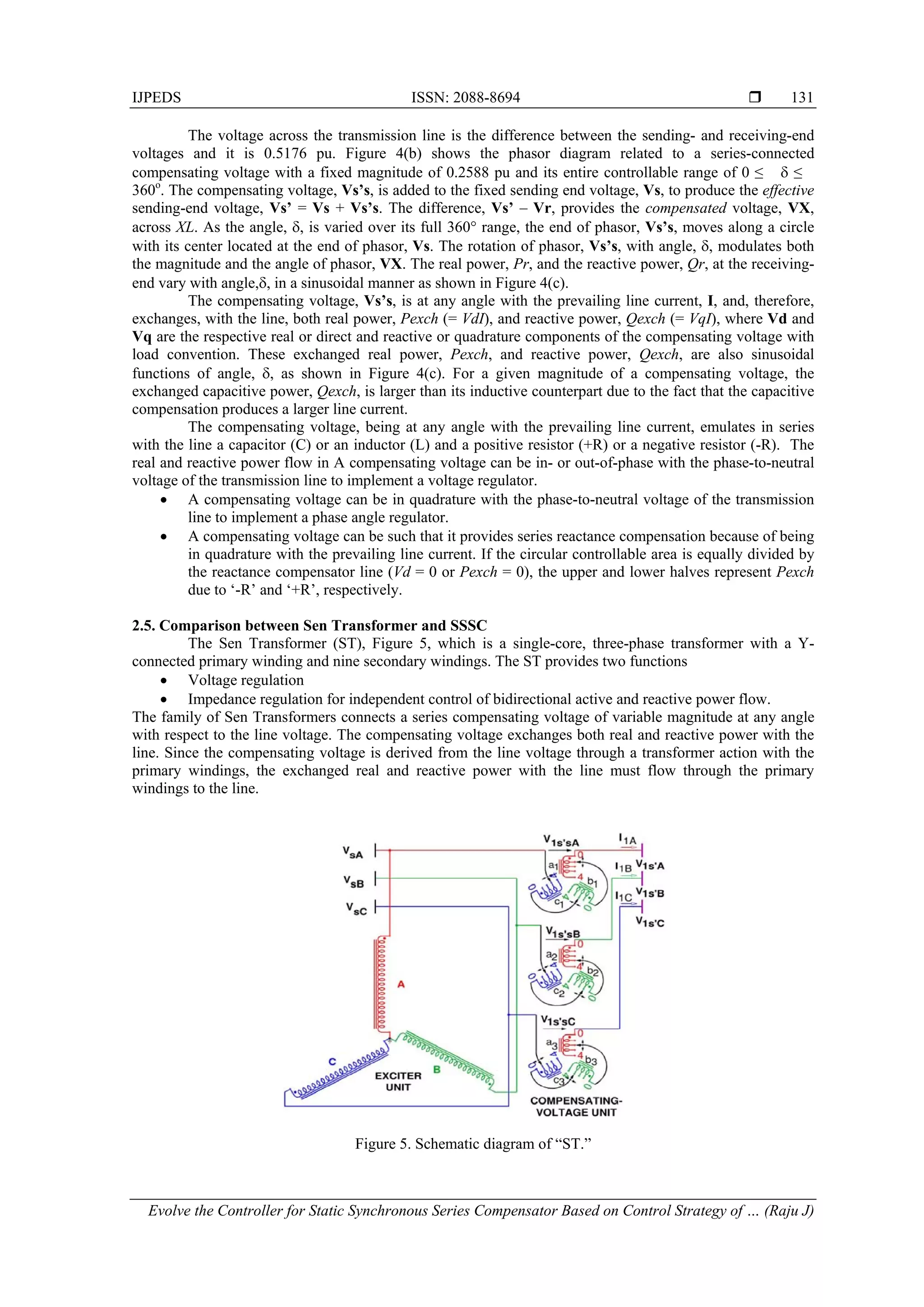
In a Sen transformer, as shown in Figure 5, there are two units: exciter unit and compensating-
voltage unit. The exciter unit consists of three primary windings (A, B, and C) that are Y-connected and
placed on each limb of a three-limb, single-core transformer. The three-phase transmission-line voltage (VsA,
VsB, and VsC) at the sending end is applied in shunt to the exciter unit.
3. STATIC SYNCHRONOUS SERIES COMPENSATION
3.1. Theory
The indirect way to implement a variable series capacitor or a variable inductor is to connect a
variable magnitude compensating voltage in series with the line and in quadrature with the line current. If the
SSSC voltage, VS, lags the line current, IL, by 90, a capacitive series compensation is obtained and if VS,
leads IL by 90, an inductive series compensation is obtained. By controlling the magnitude VS and phase
angle of the amount of series compensation can be adjusted.
3.2. Mathematical Model
Figure 1 shows a single line diagram of a simple transmission line with an inductive reactance, XL,
connecting a sending-end voltage source, Vs, and a receiving-end voltage source, Vr, respectively [6], [7]
[8].
The real and reactive power (P and Q) flow at the receiving-end voltage source are given by the
expressions
Where Vs and Vr are the magnitudes and s and s are the phase angles of the voltage sources Vs
and Vr, respectively. For simplicity, the voltage magnitudes are chosen such that Vs=Vr=V and the
difference between the phase angles is = s-r.
An SSSC, limited by its voltage and current ratings, is capable of emulating a compensating
reactance, Xq, (both inductive and capacitive) in series with the transmission line inductive reactance, XL.
Therefore, the expressions for power flow given in equation (1) become
Where Xeff is the effective reactance of the transmission line between its two ends, including the
emulated variable reactance inserted by the injected voltage source of the SSSC. The compensating
reactance, Xq, is defined to be negative when the SSSC is operated in an inductive mode and positive when
the SSSC is operated in a capacitive mode.
Figure shows an example of a simple power transmission system with an SSSC operated both in
inductive and in capacitive modes and the related phasor diagrams. The line current decreases from I0% to I-
100%, when the inductive reactance compensation, - Xq/XL, increases from 0% to 100%. The line current
increases from I0% to I33%, when the capacitive reactance compensation, Xq/XL, increases from 0% to 33%.
From equations (1) and (2), the expressions for the normalized power flow in the transmission line and the
normalized effective reactance of the transmission line can be written as
)(1cos1cos1
)(1sinsin
2
2
b
X
V
s
X
VV
Q
and
a
X
V
s
X
VV
P
L
r
L
rs
L
r
L
rs
)4(1
)3(
/1
1
L
q
L
eff
Lq
qq
X
X
X
X
XXQ
Q
P
P
)(2cos1
/1
cos1
)(2sin
/1
sin
22
22
b
XXX
V
X
V
Q
and
a
XXX
V
X
V
P
LqLeff
q
LqLeff
q
](https://image.slidesharecdn.com/1218dec135246evolvethecontrollerforsssc-171212151932/75/Evolve-the-Controller-for-Static-Synchronous-Series-Compensator-Based-on-Control-Strategy-of-Sen-Transformer-6-2048.jpg)
![IJPEDS ISSN: 2088-8694
Evolve the Controller for Static Synchronous Series Compensator Based on Control Strategy of … (Raju J)
133
The effects of the compensating reactance, Xq, on the normalized power flow in the transmission
line and the normalized effective reactance of the transmission line are shown. When the emulated reactance
is inductive, the power flow, Pq and Qq, decrease and the effective reactance, Xeff, increases as the reactance
compensation, -Xq/XL, increases. When the emulated reactance is capacitive, the power flow, Pq and Qq,
increase and the effective reactance, Xeff, decreases as the reactance compensation, Xq/XL, increases.
4. METHODOLOGY
4.1. Voltage Source Converter (VSC)
Figure 6. Basic principles of VSC
Voltage fed converter means [1], [9], it receives the dc voltage at one side and convert it to ac
voltage on the other side. The ac voltage frequency maybe variable or constant depends on the applications.
The voltage – fed inverter should have a stiff voltage source at the input, that is, its Thevenin impedance
should ideally zero. If the input voltage is not stiff a large DC capacitor can connect at the input side
irrespective of DC voltage variations. In this simulation studies also large value of capacitor (splits into two)
is connected in front of the converter.
Figure 6 shows the block diagram representation of VSC. The basic concept of voltage source
converter and current source converter has been studied [1] in details.
4.2. Principle of operation of VSC
Figure 7. Single valve operation
Figure 7 shows the principle of operation of an IGBT based single valve connection diagram. Gating
instant is not shown in Figure 3.2, for simplicity of explanation.
The capacitor voltage Vd is assumed to be a constant, supported by a large capacitor. With the
positive terminal of the capacitor is connected to the collector of the IGBT. When IGBT is turned ON, the
positive dc terminal is connected to an ac terminal at ‘A’ and the ac voltage would jump to Vd. If the current
happens to flow from +Vd to ‘A’ (through IGBT), the power would flow from the dc side to ac side (inverter
action). However, if the current happens to flow from ‘A’ to +Vd it will flow through the diode even the
IGBT is ON, and power will flow from ac side to dc side (rectifier action). Thus the valve with combinations
of diode can handle the power flow in direction, this valve and its capability to act as a rectifier or as an
inverter with instantaneous current flow in positive or negative direction respectively, is basic to voltage
source converter concepts.
ai
aV
dV
di
A
Active
dc power
C
G
E
aV
dc side
ac side
Active
and reactive
ac power
Vd](https://image.slidesharecdn.com/1218dec135246evolvethecontrollerforsssc-171212151932/75/Evolve-the-Controller-for-Static-Synchronous-Series-Compensator-Based-on-Control-Strategy-of-Sen-Transformer-7-2048.jpg)
![ ISSN: 2088-8694
IJPEDS Vol. 4, No. 1, March 2014 : 127 – 136
134
4.3. Basic Control of SSSC
The basic building block of the SSSC as shown in figure 8 is a dc-ac converter which is connected
in series with the transmission line by a coupling transformer. If the SSSC voltage, VS, lags the line current,
IL, by 90º, capacitive series compensation is obtained and if VS leads by IL 90º, inductive series compensation
is obtained. By controlling the magnitude of the amount of series compensation can be adjusted [10], [11].
The only way to control the magnitude of the converter ac voltage is by the input dc voltage. The dc
capacitor voltage control is achieved by a small phase displacement, , real power flows from the SSSC to
the transmission line and the dc capacitor is discharged. Similarly, real power flows from the transmission
line to the SSSC and the dc capacitor is charged. Besides, a small amount of real power from the
transmission line is required to compensate the converter switching and coupling transformer losses.
Figure 8. Basic Control block of SSSC
4.4. Proposed Power Flow Control using SSSC
The main function of the SSSC is to control the real power flow. This can be achieved either by
direct control of the line current or power, or alternatively by indirect control of the compensating reactance,
Xs, or series voltage, Vs. Because of practical considerations, sometimes the reactance control may be
preferred. [12] [13].
The degree of series compensation, S, is usually expressed as the ratio of the series injected
reactance, XS, to the transmission line reactance, XL. Therefore, S = (XS/XL) and the reference reactance is
SXL which is negative for capacitive and positive for inductive compensation. Figure shows the basic control
structure of the SSSC, with the series injected reactance, XS, as the reference value as shown in figure 9.
The Phase-Locked Loop (PLL) system provides the basic synchronization signal,, which is the
phase angle of the line current. XRef is compared with XS and the error is passed to a PI controller that
generates the required phase angle displacement, . The final output of the control system is the phase
angle of the SSSC voltage.](https://image.slidesharecdn.com/1218dec135246evolvethecontrollerforsssc-171212151932/75/Evolve-the-Controller-for-Static-Synchronous-Series-Compensator-Based-on-Control-Strategy-of-Sen-Transformer-8-2048.jpg)
![IJPEDS ISSN: 2088-8694
Evolve the Controller for Static Synchronous Series Compensator Based on Control Strategy of … (Raju J)
135
Figure 9. Basic Control Block for SSSC
XReff is the effective reactance of the transmission line between its two ends, including the emulated
variable reactance inserted by the injected voltage source of the SSSC. The compensating reactance, XS, is
defined to be negative when the SSSC is operated in an inductive mode and positive when the SSSC is
operated in a capacitive mode.
5. CONCLUSION
In this paper, an attempt is made to review the model of SSSC and VSC with preliminary studies for
the controller design. The power flow in the transmission line always decreases when the injected voltage by
the SSSC emulates an inductive reactance in series with the transmission line and the power flow in the
transmission line always increases when the injected voltage by the SSSC emulates a capacitive reactance in
series with the transmission line. An attempt has been made to evolve a better control strategy to control the
power flow in the transmission line using voltage source converter. The power flow control using sen
transformer discussed in [5], is considered as reference for evolving control strategy for SSSC.
ACKNOWLEDGEMENTS
I would like to acknowledge my external guide Dr. M. Arunachalam, Fellow of INAE, GM (Retd.)
at Bharat Heavy Electricals Limited, Bangalore, India. I would also like to show my special gratitude to the
Management of VIT University, Vellore, also Dr. K.K. Ray, Professor (Retd.), VIT University, India for his
valuable suggestions in many technical discussions.
REFERENCES
[1] NG Hingorani and L Gyugyi. ‘Understanding FACTS’. IEEE Press, New York. 1999.
[2] KR Padiyar. ‘FACTS Controllers in Power Transmission and Distribution’. New Age International (P) Limited,
New Delhi, India. 2007.
[3] IEEE Power Engineering Society/CIGRE, FACTS Overview, Publication 95TP108. IEEE Press, New York, 1995.
[4] KK Sen. ‘SSSC - Static Synchronous Series Compensator: Theory, Modeling and applications’. IEEE Trans. on
Power Delivery. 1998; 13(1).
[5] L Gyugyi, C Schauder, and KK Sen. ‘Static Synchronous Series Compensator: A solid state approach to the series
compensation of transmission lines’. IEEE Trans. on Power Delivery. 1997; 12(1).
[6] KK Sen and ML Sen. ‘Introducing the family of “sen” transformers: A set of power flow controlling transformers’.
IEEE Trans. Power Del. 2003; 18(1): 149–157.
PI
Reactance
Calculator
Phase
Shifter
PLL
Converter
Gate
Firing
Pulse
90º
Vinj iline
+ve sequence +ve sequence
voltage currents
*
VS
+
-L
s
Lff
X
X
S
SXX
Re
abc
o
Vinj_abc
Injected
Voltages,
generated
by the
converter
Reference
wave
Generator
I_abc
Line
Currents
](https://image.slidesharecdn.com/1218dec135246evolvethecontrollerforsssc-171212151932/75/Evolve-the-Controller-for-Static-Synchronous-Series-Compensator-Based-on-Control-Strategy-of-Sen-Transformer-9-2048.jpg)
![ ISSN: 2088-8694
IJPEDS Vol. 4, No. 1, March 2014 : 127 – 136
136
[7] KK Sen and ML Sen. ‘Comparison of the sen transformer with the unified power flow controller’. IEEE Trans.
Power Del. 2003; 18(4): 1523–1533.
[8] VK Sood. ‘Static Synchronous Series Compensator’. 2002 IEEE Canadian Conference on Electrical and Computer
Engineering, Winnipeg. 2002.
[9] Bimal K Bose. ‘Modern Power Electronics and AC Drives’. Pearson Education, New Delhi, India. 2003.
[10] S Salem and VK Sood. ‘Modeling of series voltage source converter applications with EMTP-RV’. Int. Conf. on
Power System Transients (IPST'05), Montreal. 2005.
[11] KK Sen and AJF Keri. ‘Comparison of field results and digital simulation results of voltage-sourced converter-
based FACTS controllers’. IEEE Trans. Power Del. 2003; 18(1): 300–306.
[12] AH Norouzi and AM Sharaf. ‘Two Control schemes to enhance the Dynamic Performance of the STATCOM and
SSSC’. IEEE Trans. on Power Delivery. 2005; 20(1): 435-440.
[13] Gyugyi L. ‘Dynamic Compensation of AC Transmission Lines by Solid-state Synchronous Voltage Source’. IEEE
Transactions on Power Delivery. 1994; 9(2).
BIOGRAPHIES OF AUTHORS
Raju J received B.E degree in Electrical and Electronics Engineering from Govt. College
Engineering, Bargur in 1998 and M.Tech. degree in Power Electronics form VIT University,
Vellore in 2004 and doing Ph.D (FACTS Controllers) in VIT University, Vellore, Tamilnadu,
India. Presently he is a Asst. Prof. (SG) in School of Electrical Engineering, VIT University,
Vellore. His research interest is Power Electronics Application in Powr Systems, Modeling and
Simulation in FACTS Controllers, Power Electronics and drives and Application in Reactive
Power Control.
Raju J is a member in IEEE and Life Member of System Society of India (SSI).
Kowsalya M received the B.E. degree in Electrical & Electronics Engineering and M.E.,
degree in Power Systems Engineering from Annamalai University, Tamil Nadu, India, in 1995
& 1997 respectively and Ph.D. degree from the VIT University Vellore 2011. Presently; she is
a Professor in School of Electrical Engineering, VIT University, Vellore. Her current research
interests include Power electronics applications in power systems, flexible ac transmission
system (FACTS), high-voltage dc (HVDC), power quality, Microgrid, Smart grid and
Reconfiguration.
Dr. M Kowsalya is a member in Institution of Engineers (India) (IE(I)) and the IEEE. She is a
Life Member of the Indian Society for Technical Education (ISTE) and the System Society of
India (SSI).](https://image.slidesharecdn.com/1218dec135246evolvethecontrollerforsssc-171212151932/75/Evolve-the-Controller-for-Static-Synchronous-Series-Compensator-Based-on-Control-Strategy-of-Sen-Transformer-10-2048.jpg)


![[IJET V2I5P4] Authors: Rachana Chavan, Rakesh Singh Lodhi](https://cdn.slidesharecdn.com/ss_thumbnails/ijet-v2i5p4-161107135739-thumbnail.jpg?width=640&height=640&fit=bounds)


