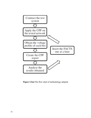
This document is a project report submitted by four students for their Bachelor of Engineering degree. The project investigates the optimal location of Interline Power Flow Controllers (IPFC) in power transmission systems. The objectives are to maintain voltage profiles and real and reactive power flows. The scope involves improving voltage profiles and power transfer capabilities using IPFCs. Recently, FACTS devices like IPFCs have attracted interest for applications like congestion management and cost reduction. The problem is that few publications have investigated IPFC locations in power systems and their effects. The report is organized into chapters covering theory, location determination methods, IPFC performance simulation and results.


![CHAPTER 2
THEORY AND LITERATURE REVIEW
2.1 Introduction
In this chapter, the basic working principle of the FACTS Controllers would
be discussed. It would also include brief overview of the continuous power flow
analysis. Lastly, the reviews of related work would also be included.
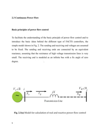
2.2 General Theory on FACTS Controllers
In general, FACTS Controllers can be divided into four categories:
• Series Controllers
• Shunt Controllers
• Combined series-series Controllers
• Combined series-shunt Controllers
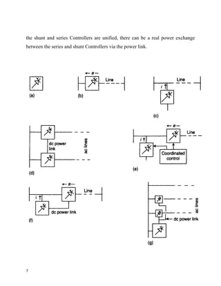
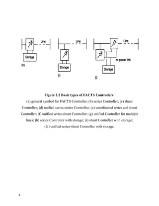
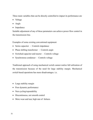
Series Controllers: [Figure 2.2(b)] The series Controller could be a variable
impedance, such as capacitor, reactor, etc., or a power electronics based variable
source of main frequency, subsynchronous and harmonic frequencies (or a
combination) to serve the desired need. In principle, all series Controllers inject
voltage in series with the line. Even a variable impedance multiplied by the current
flow through it, represents an injected series voltage in the line. As long as the
voltage is in phase quadrature with the line current, the series Controller only
supplies or consumes variable reactive power. Any other phase relationship will
involve handling of real power as well.
5](https://image.slidesharecdn.com/e9518071-32cc-421f-b480-9afed19a0745-161224082547/85/project-report-on-IPFC-10-320.jpg)
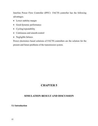
![Shunt Controllers: [Figure 2.2(c)] As in the case of series Controllers, the shunt
Controllers may be variable impedance, variable source, or a combination of these.
In principle, all shunt Controllers inject current into the system at the point of
connection. Even a variable shunt impedance connected to the line voltage causes a
variable current flow and hence represents injection of current into the line. As
long as the injected current is in phase quadrature with the line voltage, the shunt
Controller only supplies or consumes variable reactive power. Any other phase
relationship will involve handling of real power as well.
Combined series-series Controllers: [Figure 2.2(d)] This could be a combination
of separate series controllers, which are controlled in a coordinated manner, in a
multiline transmission system. Or it could be a unified Controller, Figure 1.4(d), in
which series Controllers provide independent series reactive compensation for each
line but also transfer real power among the lines via the power link. The real power
transfer capability of the unified series-series Controller, referred to as Interline
Power Flow Controller, makes it possible to balance both the real and reactive
power flow in the lines and thereby maximize the utilization of the transmission
system. Note that the term "unified" here means that the de terminals of all
Controller converters are all connected together for real power transfer.
Combined series-shunt Controllers: [Figures 2.2(e) and 2.2(f)] This could be a
combination of separate shunt and series Controllers, which are controlled in a
coordinated manner [Figure 2.2(e)], or a Unified Power Flow Controller with
series and shunt elements [Figure 2.2(f)]. In principle, combined shunt and series
Controllers inject current into the system with the shunt part of the Controller and
voltage in series in the line with the series part of the Controller. However, when
6](https://image.slidesharecdn.com/e9518071-32cc-421f-b480-9afed19a0745-161224082547/85/project-report-on-IPFC-11-320.jpg)