FACTS devices are one of the latest technologies which have been used to
improve power system dynamic and stability during recent years. However,
widespread adoption of this technology has been hampered by high cost
and reliability concerns. In this paper an economical phase imbalanced shunt
reactive compensation concept has been introduced and its ability for power
system dynamic enhancement and inter-area oscillation damping are
investigated. A hybrid phase imbalanced scheme is a shunt capacitive
compensation scheme, where two phases are compensated by fixed shunt
capacitor (C) and the third phase is compensated by a Static Synchronous
Compensator (STATCOM) in shunt with a fixed capacitor (CC). The power
system dynamic stability enhancement would be achieved by adding
a conventional Wide Area Damping Controller (WADC) to the main control
loop of the single phase STATCOM. Two different control methodologies
are proposed: a non-optimized conventional damping controller
and a conventional damping controller with optomised parameters that are
added to the main control loop of the unbalanced compensator in order to
damp the inter area oscillations. The proposed arrangement would, certainly,
be economically attractive when compared with a full three-phase
STATCOM. The proposed scheme is prosperously applied in a 13-bus
six-machine test system and various case studies are conducted to
demonstrate its ability in damping inter-area oscillations and power system
dynamic enhancement.
Enhancement of Power System Dynamics Using a Novel Series Compensation SchemeIJMER
Phase imbalanced capacitive compensation is a “hybrid” series compensation scheme, where the
series capacitive compensation in one phase is created using a single-phase TCSC in series with a fixed capacitor
(Cc), and the other two phases are compensated by fixed series capacitors (C). The TCSC control is initially set
such that its equivalent compensations at the power frequency combined with the fixed capacitor yield a
resultant compensation equal to the other two phases. Thus, the phase balance is maintained at the power
frequency while at any other frequency, a phase imbalance is created. The effectiveness of the scheme in damping
power system oscillations for various network conditions, namely different system faults and tie-line power flows is
evaluated using the MATLAB/SIMULINK Software
Comparison of Shunt Facts Devices for the Improvement of Transient Stability ...IJSRD
This paper presents, the performance of STATCOM placed at midpoint of the two machine power system and compared with the performance of SVC. The comparison of various results found for the different type of faults (single line, double line & three phase fault) occur in long transmission line, and their removal by using shunt FACTS devices is analysed. Computer simulation results under a severe disturbance condition (three phase fault) for different fault clearing times, and different line lengths are analyzed. Both controllers are implemented using MATLAB/SIMULINK. Simulation results shows that the STATCOM with conventional PI controller installed with two machine three bus systems provides better damping oscillation characteristics in rotor angle as compared to two machine power system installed with SVC. The transient stability of two machine system installed with STATCOM has been improved considerably and post settling time of the system after facing disturbance is also improved.
International Journal of Computational Engineering Research(IJCER) ijceronline
nternational Journal of Computational Engineering Research (IJCER) is dedicated to protecting personal information and will make every reasonable effort to handle collected information appropriately. All information collected, as well as related requests, will be handled as carefully and efficiently as possible in accordance with IJCER standards for integrity and objectivity.
In this paper, the voltage stability of the power system is studied during fault conditions. Enhancement of the system’s stability will be achieved by utilizing Flexible AC transmission systems (FACTS) controllers at the best place in the system. The optimum placement of (FACTS) controllers occurred on the most affected bus by the fault in the system (weakest bus). Two approaches have been used in this study to effectively obtain the best location of the (FACTS) controllers in the system. The first method is based on computing the deviation which occurs in the active power and reactive power due to the fault at each load bus at a time. Whereas the second method is performed through exploiting a MATLAB fuzzy set technique utilizing two indices: Line Flow Index (LFI) and Voltage Profile Index (VPI) during fault and steady-state conditions. The results show that both of these indices resulted in the same bus as the best location. Remedial actions in the attempt at improving in the stability of the power system are discussed taking the advantage of using (FACTS) compensation (SVC) and (STATCOM) at the most vulnerable system buses. In this work, MATLAB program with an IEEE 24 bus system is examined.
International Refereed Journal of Engineering and Science (IRJES) is a peer reviewed online journal for professionals and researchers in the field of computer science. The main aim is to resolve emerging and outstanding problems revealed by recent social and technological change. IJRES provides the platform for the researchers to present and evaluate their work from both theoretical and technical aspects and to share their views.
www.irjes.com
International Journal of Engineering Research and DevelopmentIJERD Editor
Electrical, Electronics and Computer Engineering,
Information Engineering and Technology,
Mechanical, Industrial and Manufacturing Engineering,
Automation and Mechatronics Engineering,
Material and Chemical Engineering,
Civil and Architecture Engineering,
Biotechnology and Bio Engineering,
Environmental Engineering,
Petroleum and Mining Engineering,
Marine and Agriculture engineering,
Aerospace Engineering.
Flexible alternating current transmission systems (FACTs) technology opens up new opportunities for
controlling power flow and enhancing the usable capacity of present, as well as new and upgraded lines. These
FACTs device which enables independent control of active and reactive power besides improving reliability and
quality of the supply. This paper describes the real and reactive power flow control through a short transmission
line and then compensated short transmission line with different FACTs devices are used to selection of FACTs
devices for better reactive power compensation with change in line capacitance/shunt capacitance to observe
power flow. Computer simulation by MATLAB/SIMULINK has been used to determining better reactive power.
TCSC, STATCOM, UPFC and SSSC FACTs controller with different capacitance are tested for controlling
reactive power flow.
WAMS-Based SSR Damping Controller Design for FACTS Devices and Investigating ...IJPEDS-IAES
Recent technological progresses in the wide-area measurement systems
(WAMS) are realizing the centralized controls as a breakthrough for
improving the power systems stability. The most challenging deficiency
against WAMS technology is related to communication delays. If this latency
is neglected, it can deteriorate the damping performance of closed loop
control or even degrade the system stability. This paper investigates a
conventional Wide Area Damping Controller (WADC) for a static
synchronous series compensator (SSSC) to damp out the Sub-Synchronous
Resonance (SSR) and also investigation of the destructive effect of time
delay in remote feedback signal. A new optimization algorithm called
teaching-learning-based- optimization (TLBO) algorithm has been
implemented to normalize and optimize the parameters of the global SSR
damping controller. The IEEE Second Benchmark Model is considered as the
system under study and all simulations are carried out in
MATLAB/SIMULINK environment.
Voltage Stabilization of a Wind Turbine with STATCOM Using Intelligent Contro...ijeei-iaes
Application of FACTS controller called Static Synchronous Compensator STATCOM to improve the performance of power grid with Wind System is investigated. The essential feature of the STATCOM is that it has the ability to absorb or inject fastly reactive power with power grid. Therefore the voltage regulation of the power grid with STATCOM FACTS device is achieved. Moreover restoring the stability of the wind system at suddenly step up or down in wind speed is obtained with STATCOM. This paper describes a complete simulation of voltage regulation of a wind system using STATCOM. Conventional control technique as proportional plus integral controller , and intelligent techniques as FLC and ANFIS are used in this work. The control technique is performed using MATLAB package software. The dynamic response of uncontrolled system is also investigated under wide range of disturbances. The voltage regulation by using STATCOM whose output is varied so as to maintain or control output voltage in the system. The dynamic response of controlled system is shown and comparison between the uncontrolled system and the controlled system is described to assure the validity of the proposed controller. Also comparison between the proposed control methods scheme is presented. To validate the powerful of the STATCOM FACTS controllers, the studied power system is simulated and subjected to different severe disturbances. The results prove the effectiveness of the proposed STATCOM controller in terms of fast damping the power system oscillations and restoring the power system stability and voltage.
International Journal of Engineering Research and Applications (IJERA) is an open access online peer reviewed international journal that publishes research and review articles in the fields of Computer Science, Neural Networks, Electrical Engineering, Software Engineering, Information Technology, Mechanical Engineering, Chemical Engineering, Plastic Engineering, Food Technology, Textile Engineering, Nano Technology & science, Power Electronics, Electronics & Communication Engineering, Computational mathematics, Image processing, Civil Engineering, Structural Engineering, Environmental Engineering, VLSI Testing & Low Power VLSI Design etc.
A Matlab/Simulink Model for the control scheme utilized to improve power qual...AM Publications
the wind energy generation, utilization and its grid penetration in electrical grid are increasing worldwide. The
integration of wind energy into the power system is to minimize the environmental impact on conventional plant but the injection
of the wind power into an electric grid affects the power quality. The wind generated power is always fluctuating due to its time
varying nature and causing stability problem. The power quality is determined on the basis of measurements and the norms
followed according to the guideline specified in International Electro-technical Commission standard, IEC-61400. The influence
of the wind turbine in the grid system concerning the power quality measurements are-the active power, reactive power, variation
of voltage, flicker, harmonics, and electrical behavior of switching operation and these are measured according to
national/international guidelines. The project demonstrates the power quality problem due to installation of wind turbine with
the grid. In this proposed scheme Static Compensator (STATCOM) is connected at a point of common coupling with a battery
energy storage system (BESS) to mitigate the harmonics. The battery energy storage is integrated to sustain the real power
source under fluctuating wind power. The STATCOM control scheme for the grid connected wind energy generation system for
power quality improvement is simulated using MATLAB/SIMULINK in power system block set. The effectiveness of the
proposed scheme relives the main supply source from the reactive power demand of the load and the induction generator. The
development of the grid co-ordination rule and the scheme for improvement in power quality norms as per IEC-standard on the grid has been presented.
Wind-Turbine Asynchronous Generator Synchronous Condenser with Excitation in ...IJMTST Journal
In this paper Standalone operation of a wind turbine generating system under fluctuating wind and variable load conditions is a difficult task. Moreover, high reactive power demand makes it more challenging due to the limitation of reactive capability of the wind generating system.The frequency is controlled by the Discrete Frequency Regulator block. This controller uses a standard three-phase Phase Locked Loop (PLL) system to measure the system frequency. The measured frequency is compared to the reference frequency to obtain the frequency error. This error is integrated to obtain the phase error. The phase error is then used by a Proportional-Differential (PD) controller to produce an output signal representing the required secondary load power. This signal is converted to an 8-bit digital signal controlling switching of the eight three-phase secondary loads. In order to minimize voltage disturbances, switching is performed at zero crossing of voltage.
Aircraft Electrical Power Generation & Distribution System Units Through an A...IJMTST Journal
This paper illustrates a generic Electrical Power Generation & Distribution System. The AC power frequency is variable and depends of the engine speed. The represents the generator mechanical drive and is modeled by a simple signal builder, which provides the mechanical speed of the engine shaft.The represents the power AC generator. It is composed of a modified version of the simplified synchronous machine. The mechanical input of the modified machine of 50 kW is the engine speed. The Generator Control Unit regulates the voltage of the generator to 200 volts line to line.The represents the Primary Distribution system. It is composed of three current and voltage sensors. There is also a 3-phase contactor controlled by the Generator Control Unit. Finally, a parasitic resistive load is required to avoid numerical oscillations. The section represents the secondary Power Distribution system. It is represented by 4 circuit breakers with adjustable current trip. The section represents the AC loads. There is a 4 kW Transformer and Rectifier Unit (which supplies 28 Vdc), a 12 kW induction machine (motor driving a pump), a 1 kW resistive load (lamps) and a 3 hp simplified (using an average value inverter) brushless DC drive (motor driving a ballscrew actuator)
Optimal Placement of DG for Loss Reduction and Voltage Sag Mitigation in Radi...IDES Editor
This paper presents the need to operate the power
system economically and with optimum levels of voltages has
further led to an increase in interest in Distributed
Generation. In order to reduce the power losses and to improve
the voltage in the distribution system, distributed generators
(DGs) are connected to load bus. To reduce the total power
losses in the system, the most important process is to identify
the proper location for fixing and sizing of DGs. It presents a
new methodology using a new population based meta heuristic
approach namely Artificial Bee Colony algorithm(ABC) for
the placement of Distributed Generators(DG) in the radial
distribution systems to reduce the real power losses and to
improve the voltage profile, voltage sag mitigation. The power
loss reduction is important factor for utility companies because
it is directly proportional to the company benefits in a
competitive electricity market, while reaching the better power
quality standards is too important as it has vital effect on
customer orientation. In this paper an ABC algorithm is
developed to gain these goals all together. In order to evaluate
sag mitigation capability of the proposed algorithm, voltage
in voltage sensitive buses is investigated. An existing 20KV
network has been chosen as test network and results are
compared with the proposed method in the radial distribution
system.
Transmission System Operators and Owners are required to maintain a Black Start and System
Restoration Plan that has been thoroughly verified with studies. Combustion turbines are
typically used as Black Start generators, which then are used to start larger coal and combined
cycle plants. Steady state and transient studies are normally performed to verify whether voltage
and frequency are within limits so as not to interrupt the restoration process, and to ensure
large induction motors associated with the power plants can be started. In recent times, Battery
Energy Storage Systems (BESS) are being considered for black start system restoration, in
lieu of combustion turbines. The models that are currently available for BESS in transmission
planning software are meant to study synchronized operation of BESS, rather than an islanded
operation. In this paper, a modeling technique is presented for evaluating BESS for black start
system restoration. The performance of BESS for black start system restoration is compared
with the performance of a combustion turbine.
Power Quality Improvement in Power System using UPFCijtsrd
Occurrence of a fault in a power system causes transients. To stabilize the system, Power System Stabilizer (PSS) and Automatic Voltage Regulator (AVR) are used. Load flow analysis is done to analyze the transients introduced in the system due to the occurrence of faults. The Flexible Alternating Current Transmission (FACTS) devices such as UPFC are becoming important in suppressing power system oscillations and improving system damping. The UPFC is a solid-state device, which can be used to control the active and reactive power. This paper considers a power system as a case study for investigating the performance of UPFC is achieving stability. By using a UPFC the oscillation introduced by the faults, the voltage deviations and speed deviations can be damped out quickly than a system without a UPFC. The effectiveness of UPFC in suppressing power system oscillation is investigated by analyzing their voltage deviations and reactive power support in this paper. A proportional integral (PI) controller has been employed for the UPFC. It is also shown that a UPFC can control independently the real and reactive power flow in a transmission line. Navneet Kaur | Gagan Deep Yadav"Power Quality Improvement in Power System using UPFC" Published in International Journal of Trend in Scientific Research and Development (ijtsrd), ISSN: 2456-6470, Volume-2 | Issue-1 , December 2017, URL: http://www.ijtsrd.com/papers/ijtsrd7139.pdf http://www.ijtsrd.com/engineering/electrical-engineering/7139/power-quality-improvement-in-power-system-using-upfc/navneet-kaur
International Journal of Engineering Research and DevelopmentIJERD Editor
Electrical, Electronics and Computer Engineering,
Information Engineering and Technology,
Mechanical, Industrial and Manufacturing Engineering,
Automation and Mechatronics Engineering,
Material and Chemical Engineering,
Civil and Architecture Engineering,
Biotechnology and Bio Engineering,
Environmental Engineering,
Petroleum and Mining Engineering,
Marine and Agriculture engineering,
Aerospace Engineering.
Static VAR Compensators (SVCs) is a Flexible Alternating Current Transmission System (FACTS) device that can control the power flow in transmission lines by injecting capacitive or inductive current components at the midpoint of interconnection line or in load areas. This device is capable of minimizing the overall system losses and concurrently improves the voltage stability. A line index, namely SVSI becomes indicator for the placement of SVC and the parameters of SVCs are tuned by using the multi-objective evolutionary programming technique, effectively able to control the power. The algorithm was tested on IEEE-30 Bus Reliability Test System (RTS). Comparative studies were conducted based on the performance of SVC in terms of their location and sizing for installations in power system.
Impact of hybrid FACTS devices on the stability of the Kenyan power system IJECEIAES
Flexible alternating current transmission system (FACTS) devices are deployed for improving power system’s stability either singly or as a combination. This research investigates hybrid FACTS devices and studies their impact on voltage, small-signal and transient stability simultaneously under various system disturbances. The simulations were done using five FACTS devices-static var compensator (SVC), static synchronous compensator (STATCOM), static synchronous series compensators (SSSC), thyristor controlled series compensator (TCSC) and unified power flow controller (UPFC) in MATLAB’s power system analysis toolbox (PSAT). These five devices were grouped into ten pairs and tested on Kenya’s transmission network under specific contingencies: the loss of a major generating machine and/or transmission line. The UPFC-STATCOM pair performed the best in all the three aspects under study. The settling times were 3 seconds and 3.05 seconds respectively for voltage and rotor angle improvement on the loss of a major generator at normal operation. The same pair gave settling times of 2.11 seconds and 3.12 seconds for voltage and rotor angle stability improvement respectively on the loss of a major transmission line at 140% system loading. From the study, two novel techniques were developed: A performance-based ranking system and classification for FACTS devices.
Voltage profile Improvement Using Static Synchronous Compensator STATCOMINFOGAIN PUBLICATION
Static synchronous compensator (STATCOM) is a regulating device used in AC transmission systems as a source or a sink of reactive power. The most widely utilization of the STATCOM is in enhancing the voltage stability of the transmission line. A voltage regulator is a FACTs device used to adjust the voltage disturbance by injecting a controllable voltage into the system. This paper implement Nruro-Fuzzy controller to control the STATCOM to improve the voltage profile of the power network. The controller has been simulated for some kinds of disturbances and the results show improvements in voltage profile of the system. The performance of STATCOM with its controller was very close within 98% of the nominal value of the busbar voltage.
International Journal of Engineering Research and DevelopmentIJERD Editor
Electrical, Electronics and Computer Engineering,
Information Engineering and Technology,
Mechanical, Industrial and Manufacturing Engineering,
Automation and Mechatronics Engineering,
Material and Chemical Engineering,
Civil and Architecture Engineering,
Biotechnology and Bio Engineering,
Environmental Engineering,
Petroleum and Mining Engineering,
Marine and Agriculture engineering,
Aerospace Engineering.
In this paper a grid interconnected system with wind energy source linked with a FACTs based SSFC device ( Static switched filter compensator ) at load for enhancing power quality is considered .Analysis is done for the proposed system by varying Carrier frequency over a wide range and observed system performance at all 3 busses wise Grid bus, Generator Bus and Load Bus. Two regulators are used to organize the FACTS SSFC-device, these are based on a tri-loop dynamic error obsessed inter-coupled input to VSC controller. Investigation is made in MATLAB/SIMULINK Environment for the proposed system ,it is observed that system performance in terms of percentage Total harmonic Distortion is satisfactory along with the Enhanced Power Quality.
A Review on Optimization of Coordinated Control Plan for PSS and STATCOM Devi...ijtsrd
This thesis work introduces the control of the coordinates of PSS and STATCOM to damp the inter field oscillations of the multi machine system. In previous eras, PSS was used as a local controller in multi machine systems to dampen such oscillations between fields. Reactive FACTS devices, such as synchronous static compensators STATCOM are taken into account and evaluated for their design of a damping controller. STATCOM is a reactive power compensator based on a voltage source converter that uses electronic power devices with stop capacity as switching devices. Its main function is to support the voltage of the bus from which it is connected to the system by providing a quick response to the delivery or absorption of reactive power. In order to dampen the power oscillations, the power oscillation damping function POD must be used, in which its output is summed with the voltage reference at the input of STATCOM. Gautam Kumar | Prof. Govind Prasad Pandiya "A Review on Optimization of Coordinated Control Plan for PSS and STATCOM Devices to Improve Power System Oscillation" Published in International Journal of Trend in Scientific Research and Development (ijtsrd), ISSN: 2456-6470, Volume-4 | Issue-4 , June 2020, URL: https://www.ijtsrd.com/papers/ijtsrd30922.pdf Paper Url :https://www.ijtsrd.com/engineering/electronics-and-communication-engineering/30922/a-review-on-optimization-of-coordinated-control-plan-for-pss-and-statcom-devices-to-improve-power-system-oscillation/gautam-kumar
Comparison of Shunt Facts Devices for the Improvement of Transient Stability ...IJSRD
This paper presents, the performance of STATCOM placed at midpoint of the two machine power system and compared with the performance of SVC. The comparison of various results found for the different type of faults (single line, double line & three phase fault) occur in long transmission line, and their removal by using shunt FACTS devices is analysed. Computer simulation results under a severe disturbance condition (three phase fault) for different fault clearing times, and different line lengths are analyzed. Both controllers are implemented using MATLAB/SIMULINK. Simulation results shows that the STATCOM with conventional PI controller installed with two machine three bus systems provides better damping oscillation characteristics in rotor angle as compared to two machine power system installed with SVC. The transient stability of two machine system installed with STATCOM has been improved considerably and post settling time of the system after facing disturbance is also improved.
Efficacy of Facts in Power Oscillation Damping and Renewable IntegrationIOSRJEEE
This paper discusses about the approach towards effective power oscillation damping, root causes for the genesis of power oscillation and various methodologies adopted to eradicate it.This paper presents an unified approach of FACTS controller installation in order to ensure effective power oscillation damping. The power oscillations, if not controlled within time, may aggravate the entire power system’s functioning and ultimate outcome as blackout. The network congestion has been a matter of serious concern to utility operations due to classical transmission corridors and inadequate controllers’ deployment. The necessity of system regulations demands an adequate controller for matching the power requirement variability and this has been demonstrated with STATCOM control feature. This controller enhances the Available Transfer Capability along with security and reliability. IEEE 14 Bus system is simulated and studied with various scenarios with the help of MATLAB and PSAT to identify various complexities and to resolve these issues so as to enhance the ATC, reliability and security
International Journal of Engineering Research and DevelopmentIJERD Editor
Electrical, Electronics and Computer Engineering,
Information Engineering and Technology,
Mechanical, Industrial and Manufacturing Engineering,
Automation and Mechatronics Engineering,
Material and Chemical Engineering,
Civil and Architecture Engineering,
Biotechnology and Bio Engineering,
Environmental Engineering,
Petroleum and Mining Engineering,
Marine and Agriculture engineering,
Aerospace Engineering.
Improvement of Power System Oscillation by using Coordinated Control Plan for...ijtsrd
This thesis work introduces the control of the coordinates of PSS and STATCOM to damp the inter field oscillations of the multi machine system. In previous eras, PSS was used as a local controller in multi machine systems to dampen such oscillations between fields. Reactive FACTS devices, such as synchronous static compensators STATCOM are taken into account and evaluated for their design of a damping controller. STATCOM is a reactive power compensator based on a voltage source converter that uses electronic power devices with stop capacity as switching devices. Its main function is to support the voltage of the bus from which it is connected to the system by providing a quick response to the delivery or absorption of reactive power. In order to dampen the power oscillations, the power oscillation damping function POD must be used, in which its output is summed with the voltage reference at the input of STATCOM. Gautam Kumar | Prof. Girraj Solanki "Improvement of Power System Oscillation by using Coordinated Control Plan for PSS and STATCOM Devices" Published in International Journal of Trend in Scientific Research and Development (ijtsrd), ISSN: 2456-6470, Volume-4 | Issue-4 , June 2020, URL: https://www.ijtsrd.com/papers/ijtsrd30923.pdf Paper Url :https://www.ijtsrd.com/engineering/electronics-and-communication-engineering/30923/improvement-of-power-system-oscillation-by-using-coordinated-control-plan-for-pss-and-statcom-devices/gautam-kumar
Voltage Compensation in Wind Power System using STATCOM Controlled by Soft Co...IJECEIAES
When severe voltage sags occur in weak power systemsassociated with gridconnected wind farms employing doubly fed induction generators, voltageinstability occurs, which may lead to forced disconnection of wind turbine.Shunt flexible AC transmission system devices like static synchronous compensator (STATCOM) may be harnessed to provide voltage support bydynamic injection of reactive power.In this work, the STATCOM providedvoltage compensation at the point of common coupling in five test cases,namely, simultaneous occurrence of step change (drop) in wind speed and dip in grid voltage, single line to ground, line to line, double line to groundfaults and sudden increment in load by more than a thousand times. Threetechniques were employed to control the STATCOM, namely, fuzzy logic,particle swarm optimization and a combination of both. A performancecomparison was made among the three soft computing techniques used tocontrol the STATCOM on the basis of the amount of voltage compensationoffered at the point of common coupling. The simulations were done with thehelp of SimPowerSystems available with MATLAB / SIMULINK and theresults validated that the STATCOM controlled by all the three techniques offered voltage compensation in all the cases considered.
The International Journal of Engineering & Science is aimed at providing a platform for researchers, engineers, scientists, or educators to publish their original research results, to exchange new ideas, to disseminate information in innovative designs, engineering experiences and technological skills. It is also the Journal's objective to promote engineering and technology education. All papers submitted to the Journal will be blind peer-reviewed. Only original articles will be published.
The papers for publication in The International Journal of Engineering& Science are selected through rigorous peer reviews to ensure originality, timeliness, relevance, and readability.
USING SSSC & STATCOM --IMPROVE TRANSIENT STABILITY--P & Q OSICALLATIONSIJSRD
In a deregulated power system, the electric power demand is extending ordinary which may lead to overloads and loss of generation. Transient stability studies put a fundamental part in power systems, which give information related to the capacity of a power structure to stay in synchronism during major disturbances resulting from either the loss of generation or transmission facilities, sudden or sustained changes. The examination of transient quality is discriminating to work the power structure more secure and this paper focuses on growing the transient relentlessness using FACTS devices like Static Synchronous Series Compensator (SSSC) and static synchronous compensator (STATCOM). These FACTS contraptions are in a perfect world set on transmission structure using Sensitivity approach framework.
Location of Shunt FACTS Devices for First-Swing Stability Enhancement in Inte...Editor IJMTER
This paper deals with the location of shunt FACTS devices to improve transient stability
in a long transmission line with predefined direction of real power flow. Shunt Flexible AC
Transmission System (FACTS) devices, when placed at the mid-point of a long transmission line,
play an important role in controlling the reactive power flow to the power network and hence both
the system voltage fluctuations and transient stability. The validity of the mid-point location of shunt
FACTS devices was verified using Simulink, with different shunt FACTS devices, namely static var
compensator (SVC) and static synchronous compensator (STATCOM) in a long transmission line
using the actual line model. It has been observed that the FACTS devices, when placed slightly offcentre towards sending-end, give better performance in improving transient stability and the location
depends on the amount of local/through load. The results are experimented and simulated on
MATLAB/Simulink environment.
Phase Measurement Units based FACT’s Devices for the Improvement of Power Sys...IJECEIAES
This paper describes the importance of FACTS devices; it presents the outcome of the study of its reflectance on the performance of power system networks. It seeks to increase and guarantee the fact and accuracy of response systems under disturbance conditions when the phase measurement units are introduced as Real-Time Measurement (RTM) stations. This paper also describes the importance of FACTS devices. The combination of FACTS devices and PMUs is presented to increase the controllability performance of power systems. This paper demonstrates how PMUs measure voltage, current and their angles. It provides, through a communication link, a Phase Angle Data Concentrator (PDC) to make an appropriate decision to correct the power system state using the FACTS device (TCSC). We utilized the Graph-Theoretic Algorithm to optimize the number and location of PMUs. The technique proposed was tested on the Iraqi National Super Grid’s 24bus network, Diyala City’s regional 10bus network and the 14bus IEEE standard test system. The MATLAB/PSAT package was utilized for the simulation of results. It is evident that our proposed algorithm and technique achieved the purpose of this paper as confirmed by the level of accuracy of the results obtained from most of the cases tested.
Similar to Inter-Area Oscillation Damping using an STATCOM Based Hybrid Shunt Compensation Scheme (20)
Fuzzy Gain-Scheduling Proportional–Integral Control for Improving the Speed B...IJPEDS-IAES
In this article, we have set up a vector control law of induction machine
where we tried different type of speed controllers. Our control strategy is of
type Field Orientated Control (FOC). In this structure we designed a Fuzzy
Gain-Scheduling Proportional–Integral (Pi) controller to obtain best result
regarding the speed of induction machine. At the beginning we designed a Pi
controller with fixed parameters. We came up to these parameters by
identifying the transfer function of this controller to that of Broïda (second
order transfer function). Then we designed a fuzzy logic (FL) controller.
Based on simulation results, we highlight the performances of each
controller. To improve the speed behaviour of the induction machine, we
have designend a controller called “Fuzzy Gain-Scheduling Proportional–
Integral controller” (FGS-PI controller) which inherited the pros of the
aforementioned controllers. The simulation result of this controller will
strengthen its performances.
Advance Technology in Application of Four Leg Inverters to UPQCIJPEDS-IAES
This article presents a novel application of four leg inverter with
conventional Sinusoidal Pulse Width Modulation (SPWM) Scheme to
Unified Power Quality Conditioner (UPQC). The Power Quality problem
became burning issues since the starting of high voltage AC transmission
system. Hence, in this article it has been discussed to mitigate the PQ issues
in high voltage AC systems through a three phase Unified Power Quality
Conditioner (UPQC) under various conditions, such as harmonic mitigation
scheme, non linear loads, sag and swell conditions as well. Also, it proposes
to control harmoincs with various artificial intelligent techniques. Thus
application of these control technique such as Neural Networks (ANN)
Fuzzy Logic makes the system performance in par with the standards
and also compared with existing system. The simulation results based on
MATLAB/Simulink are discussed in detail to support the concept developed
in the paper.
Modified SVPWM Algorithm for 3-Level Inverter Fed DTC Induction Motor DriveIJPEDS-IAES
In this paper, a modified space vector pulse width modulation (MSVPWM)
algorithm is developed for 3-level inverter fed direct torque controlled
induction motor drive (DTC-IMD). MSVPWM algorithm simplifies
conventional space vector pulse width modulation (CSVPWM) algorithm for
multilevel inverter (MLI), whose complexity lies in sector/subsector/subsubsector
identification; which will commensurate with number of levels. In
the proposed algorithm sectors are identified as in two level inverter
and subsectors/sub-subsectors are identified by shifting the original reference
vector to sector 1 (S1). This is valid due to the fact that a three level space
vector plane is a composition of six two level space planes, and are
symmetrical with reference to six pivot states. Switching state/sequence
selection is also very important while dealing with SVPWM strategy for
MLI. In the proposed algorithm out of 27 available switching states apt
switching state is selected based on sector and subsector number, such that
voltage ripple is considerably less. To validate the proposed algorithm, it is
tested on a three level neutral point clamped (NPC) inverter fed DTC-IMD.
The performance of the MSVPWM algorithm is analyzed by comparing no
load stator current ripple of the three level DTC-IMD with two level
DTC-IMD. Significant reduction in steady state torque and flux ripple is
observed. Hence, reduced acoustic noise is a distinctive facet of the proposed
method.
Modelling of a 3-Phase Induction Motor under Open-Phase Fault Using Matlab/Si...IJPEDS-IAES
The d-q model of Induction Motors (IMs) has been effectively used as an
efficient method to analyze the performance of the induction machines. This
study presents a step by step Matlab/Simulink implementation
of a star-connected 3-phase IM under open-phase fault (faulty 3-phase IM)
using d-q model. The presented technique in this paper can be simply
implemented in one block and can be made available for control purposes.
The simulated results provide to show the behavior of the star-connected 3-phase IM under open-phase fault condition.
Performance Characteristics of Induction Motor with FielIJPEDS-IAES
With development of power electronics and control Theories, the AC motor
control becomes easier. So the AC motors are used instead of the DC motor
in the drive applications. With this development, a several methods of control
are invented. The field oriented control and direct torque control are from the
best methods to control the drive systems. This paper is compared between
the field oriented control and direct torque control to show the advantages
and disadvantages of these methods of controls. This study discussed the
effects of these methods of control on the total harmonic distortion of the
current and torque ripples. This occurs through study the performance
characteristics of the AC motor. The motor used in this study is an induction
motor. This study is simulated through the MATLAB program.
A Novel Modified Turn-on Angle Control Scheme for Torque- Ripple Reduction in...IJPEDS-IAES
In recent years, Switched Reluctance Motors (SRM) have been dramatically
considered with both researchers and industries. SRMs not only have a
simple and reliable structure, but also have low cost production process.
However, discrete torque production of SRM along with intensive magnetic
saturation in stator and rotor cores are the major drawbacks of utilizing in
variety of industrial applications and also causes the inappropriate torque
ripples. In this paper, a modified logical-rule-based Torque Sharing Function
(TSF) method is proposed considering turn-on angle control. The optimized
turn-on angle for conducting each phase is achieved by estimating the
inductance curve in the vicinity of unaligned position and based on an
analytical solution for each phase voltage equation. Simulation results on a
four-phase switched reluctance motor and comparison with the conventional
methods validates the effectiveness of the proposed method.
Modeling and Simulation of Induction Motor based on Finite Element AnalysisIJPEDS-IAES
This paper presents the development of a co-simulation platform of induction
motor (IM). For the simulation, a coupled model is introduced which
contains the control, the power electronics and also the induction machine.
Each of these components is simulated in different software environments.
So, this study provides an advanced modeling and simulation tools for IM
which integrate all the components into one common simulation platform
environment. In this work, the IM is created using Ansys-Maxwell based on
Finite Element Analysis (FEA), whereas the power electronic converter is
developed in Ansys-Simplorer and the control scheme is build in MATLABSimulink
environment. Such structure can be useful for accurate design
and allows coupling analysis for more realistic simulation. This platform is
exploited to analyze the system models with faults caused by failures of
different drive’s components. Here, two studies cases are presented: the first
is the effects of a faulty device of the PWM inverter, and the second case is
the influence of the short circuit of two stator phases. In order to study the
performance of the control drive of the IM under fault conditions,
a co-simulation of the global dynamic model has been proposed to analyze
the IM behavior and control drives. In this work, the co-simulation has been
performed; furthermore the simulation results of scalar control allowed
verifying the precision of the proposed FEM platform.
Comparative Performance Study for Closed Loop Operation of an Adjustable Spee...IJPEDS-IAES
In this paper an extensive comparative study is carried out between PI
and PID controlled closed loop model of an adjustable speed Permanent
Magnet Synchronous Motor (PMSM) drive. The incorporation of Sinusoidal
Pulse Width Modulation (SPWM) strategy establishes near sinusoidal
armature phase currents and comparatively less torque ripples without
sacrificing torque/weight ratio. In this closed loop model of PMSM drive, the
information about reference speed is provided to a speed controller, to ensure
that actual drive speed tracks the reference speed with ideally zero steady
state speed error. The entire model of PMSM closed loop drive is divided
into two loops, inner loop current and outer loop speed. By taking the
different combinations of two classical controllers (PI & PID) related with
two loop control structure, different approximations are carried out. Hence a
typical comparative study is introduced to familiar with the different
performance indices of the system corresponding to time domain and
frequency domain specifications. Therefore overall performance of closed
loop PMSM drive is tested and effectiveness of controllers will be
determined for different combinations.
Novel Discrete Components Based Speed Controller for Induction MotorIJPEDS-IAES
This paper presents an electronic design based on general purpose discrete
components for speed control of a single phase induction motor drive. The
MOSFETs inverter switching is controlled using Sampled Sinusoidal Pulse
Width Modulation (SPWM) techniques with V/F method based on Voltage
Controlled Oscillator (VCO). The load power is also controlled by a novel
design to produce a suitable SPWM pulse. The proposed electronic system
has ability to control the output frequency with flexible setting of lower limit
to less than 1 Hz and to higher frequency limits to 55 Hz. Moreover, the
proposed controller able to control the value of load voltage to frequency
ratio, which plays a major parameter in the function of IM speed control.
Furthermore, the designed system is characterized by easy manufacturing
and maintenance, high speed response, low cost, and does not need to
program steps as compared to other systems based on Microcontroller
and digital signal processor (DSP) units. The complete proposed electronic
design is made by the software of NI Multisim version 11.0 and all the
internal sub-designs are shown in this paper. Simulation results show the
effectiveness of electronic design for a promising of a high performance IM
PWM drive.
Sensorless Control of a Fault Tolerant PMSM Drives in Case of Single-Phase Op...IJPEDS-IAES
This paper introduces a sensorless-speed-controlled PMSM motor fed by a
four-leg inverter in case of a single phase open circuit fault regardless in
which phase is the fault. To minimize the system performance degradation
due to a single phase open circuit fault, a fault tolerant control strategy that
includes taking appropriate actions to control the two remaining healthy
currents is used in addition to use the fourth leg of the inverter. Tracking the
saliency is done through measuring the dynamic current responses of the
healthy phases of the PMSM motor due the IGBT switching actions using the
fundamental PWM method without introducing any modification to the
operation of the fourth leg of the inverter. Simulation results are provided to
verify the effectiveness of the proposed strategy for sensorless controlling of
a PMSM motor driven by a fault-tolerant four-phase inverter over a wide
speed ranges under the case of a single phase open circuit.
Improved Stator Flux Estimation for Direct Torque Control of Induction Motor ...IJPEDS-IAES
Stator flux estimation using voltage model is basically the integration of the
induced stator back electromotive force (emf) signal. In practical
implementation the pure integration is replaced by a low pass filter to avoid
the DC drift and saturation problems at the integrator output because of the
initial condition error and the inevitable DC components in the back emf
signal. However, the low pass filter introduces errors in the estimated stator
flux which are significant at frequencies near or lower than the cutoff
frequency. Also the DC components in the back emf signal are amplified at
the low pass filter output by a factor equals to . Therefore, different
integration algorithms have been proposed to improve the stator flux
estimation at steady state and transient conditions. In this paper a new
algorithm for stator flux estimation is proposed for direct torque control
(DTC) of induction motor drives. The proposed algorithm is composed of a
second order high pass filter and an integrator which can effectively
eliminates the effect of the error initial condition and the DC components.
The amplitude and phase errors compensation algorithm is selected such that
the steady state frequency response amplitude and phase angle are equivalent
to that of the pure integrator and the multiplication and division by stator
frequency are avoided. Also the cutoff frequency selection is improved; even
small value can filter out the DC components in the back emf signal. The
simulation results show the improved performance of the induction motor
direct torque control drive with the proposed stator flux estimation algorithm.
The simulation results are verified by the experimental results.
Minimization of Starting Energy Loss of Three Phase Induction Motors Based on...IJPEDS-IAES
The purpose of this paper is to minimize energy losses consumed by three
phase induction motors during starting with wide range of load torque from
no load to full load. This will limit the temperature rise and allows for more
numbers of starting during a definite time. Starting energy losses
minimization is achieved by controlling the rate of increasing voltage
and frequency to start induction motor under certain load torque within a
definite starting time. Optimal voltage and frequency are obtained by particle
swarm optimization (PSO) tool according to load torque. Then, outputs of the
PSO are used to design a neuro-fuzzy controller to control the output voltage
and frequency of the inverter during starting for each load torque. The
starting characteristics using proposed method are compared to that of direct
on line and V/F methods. A complete model of the system is developed using
SIMULINK/MATLAB.
Hardware Implementation of Solar Based Boost to SEPIC Converter Fed Nine Leve...IJPEDS-IAES
Multi level inverters are widely used in high power applications because of
low harmonic distortion. This paper deals with the simulation
and implementation of PV based boost to SEPIC converter with multilevel
inverter. The output of PV system is stepped up using boost to sepic
converter and it is converted into AC using a multilevel inverter.
The simulation and experimental results with the R load is presented in this
paper. The FFT analysis is done and the THD values are compared. Boost to
SEPIC converter is proposed to step up the voltage to the required value. The
experimental results are compared with the simulation results. The results
indicate that nine level inverter system has better performance than seven
level inverter system.
Transformer Less Voltage Quadrupler Based DC-DC Converter with Coupled Induct...IJPEDS-IAES
In this paper a voltage quadrupler dc-dc converter with coupled inductor
and π filter is presented. The use of the coupled inductor reduces the high
leakage inductance which is present in a transformer enabled converter.
The output ripples in the converter is reduced by providing a π filter.
The interleaved voltage quadrupler is used in this system in order to boost the
output voltage. The voltage multiplier improves the output voltage gain.
The main advantage of this system is more voltage gain when compared with
the transformer eneabled circuit and the overall efficiency of the system is
improved. The circuit is simple to control. As a final point of this research,
the simulation and the hardware investigational results are presented to
demonstrate the effectiveness of this proposed converter.
IRAMY Inverter Control for Solar Electric VehicleIJPEDS-IAES
Solar Electric Vehicles (SEV) are considered the future vehicles to solve the issues of air pollution, global warming, and the rapid decreases of the petroleum resources facing the current transportation technology. However, SEV are still facing important technical obstacles to overcome. They include batteries energy storage capacity, charging times, efficiency of the solar panels and electrical propulsion systems. Solving any of those problems and electric vehicles will compete-complement the internal combustion engines vehicles. In the present work, we propose an electrical propulsion system based on three phase induction motor in order to obtain the desired speed and torque with less power loss. Because of the need to lightweight nature, small volume, low cost, less maintenance and high efficiency system, a three phase squirrel cage induction motor (IM) is selected in the electrical propulsion system. The IM is fed from three phase inverter operated by a constant V/F control method and Space Vector Pulse Width Modulation (SVPWM) algorithm. The proposed control strategy has been implemented on the texas instruments TM320F2812 Digital Signal Processor (DSP) to generate SVPWM signal needed to trigger the gates of IGBT based inverter. The inverter used in this work is a three phase inverter IRAMY20UP60B type. The experimental results show the ability of the proposed control strategy to generate a three-phase sine wave signal with desired frequency. The proposed control strategy is experimented on a locally manufactured EV prototype. The results show that the EV prototype can be propelled to speed up to 60km/h under different road conditions.
Design and Implementation of Single Phase AC-DC Buck-Boost Converter for Powe...IJPEDS-IAES
This paper discusses the Power Factor Correction (PFC) for single phase AC-DC Buck-Boost Converter (BBC) operated in Continuous Conduction Mode (CCM) using inductor average current mode control. The proposed control technique employs Proportional-Integral (PI) controller in the outer voltage loop and the Inductor Average Current Mode Control (IACMC) in the inner current loop for PFC BBC. The IACMC has advantages such as robustness when there are large variations in line voltage and output load. The PI controller is developed by using state space average model of BBC. The simulation of the proposed system with its control circuit is implemented in MatLab/Simulink. The simulation results show a nearly unity power factor can be attained and there is almost no change in power factor when the line frequency is at various ranges. Experimental results are provided to show its validity and feasibility.
Improvement of Wind farm with PMSG using STATCOMIJPEDS-IAES
This paper studies about the dynamic performance of the Permanent Magnet Synchronous Generator with Static Synchronous Compensator (STATCOM) for Wind farm integration. A whole dynamic model of wind energy conversion system (WECS) with PMSG and STATCOM are established in a MATLAB environment. With this model the dynamic behaviour of the generator and the overall system has been studied to determine the performance of them with and without STATCOM. Final results portrays that the WECS based PMSG with STATCOM improves the transient response of the wind farm when the system is in fault.
Modeling and Control of a Doubly-Fed Induction Generator for Wind Turbine-Gen...IJPEDS-IAES
This paper presents a vector control direct (FOC) of double fed induction generator intended to control the generated stator powers. This device is intended to be implemented in a variable-speed wind-energy conversion system connected to the grid. In order to control the active and reactive power exchanged between the machine stator and the grid, the rotor is fed by a bi-directional converter. The DFIG is controlled by standard relay controllers. Details of the control strategy and system simulation were performed using Simulink and the results are presented in this here to show the effectiveness of the proposed control strategy.
A Review on Design and Development of high Reliable Hybrid Energy Systems wit...IJPEDS-IAES
Hybrid Energy system is a combination of two or more different types of energy resources. Now a day this hybrid energy system plays key role in various remote area power applications. Hybrid energy system is more reliable than single energy system. This paper deals with high reliable hybrid energy system with solar, wind and micro hydro resources. The proposed hybrid system cable of multi mode operation and high reliable due to non communicated based controllers (Droop Characteristic Control) are used for optimal power sharing. Size of battery can be reduced because hydro used as back up source and Maximum power point Tracking also applied to solar and wind energy systems.
Fuzzy Sliding Mode Control for Photovoltaic SystemIJPEDS-IAES
In this study, a fuzzy sliding mode control (FSMC) based maximum power point tracking strategy has been applied for photovoltaic (PV) system. The key idea of the proposed technique is to combine the performances of the fuzzy logic and the sliding mode control in order to improve the generated power for a given set of climatic conditions. Different from traditional sliding mode control, the developed FSMC integrates two parts. The first part uses a fuzzy logic controller with two inputs and 25 rules as an equivalent controller while the second part is designed for an online adjusting of the switching controller’s gain using a fuzzy tuner with one input and one output. Simulation results showed the effectiveness of the proposed approach achieving maximum power point. The fuzzy sliding mode (FSM) controller takes less time to track the maximum power point, reduced the oscillation around the operating point and also removed the chattering phenomena that could lead to decrease the efficiency of the photovoltaic system.
Hierarchical Digital Twin of a Naval Power SystemKerry Sado
A hierarchical digital twin of a Naval DC power system has been developed and experimentally verified. Similar to other state-of-the-art digital twins, this technology creates a digital replica of the physical system executed in real-time or faster, which can modify hardware controls. However, its advantage stems from distributing computational efforts by utilizing a hierarchical structure composed of lower-level digital twin blocks and a higher-level system digital twin. Each digital twin block is associated with a physical subsystem of the hardware and communicates with a singular system digital twin, which creates a system-level response. By extracting information from each level of the hierarchy, power system controls of the hardware were reconfigured autonomously. This hierarchical digital twin development offers several advantages over other digital twins, particularly in the field of naval power systems. The hierarchical structure allows for greater computational efficiency and scalability while the ability to autonomously reconfigure hardware controls offers increased flexibility and responsiveness. The hierarchical decomposition and models utilized were well aligned with the physical twin, as indicated by the maximum deviations between the developed digital twin hierarchy and the hardware.
Online aptitude test management system project report.pdfKamal Acharya
The purpose of on-line aptitude test system is to take online test in an efficient manner and no time wasting for checking the paper. The main objective of on-line aptitude test system is to efficiently evaluate the candidate thoroughly through a fully automated system that not only saves lot of time but also gives fast results. For students they give papers according to their convenience and time and there is no need of using extra thing like paper, pen etc. This can be used in educational institutions as well as in corporate world. Can be used anywhere any time as it is a web based application (user Location doesn’t matter). No restriction that examiner has to be present when the candidate takes the test.
Every time when lecturers/professors need to conduct examinations they have to sit down think about the questions and then create a whole new set of questions for each and every exam. In some cases the professor may want to give an open book online exam that is the student can take the exam any time anywhere, but the student might have to answer the questions in a limited time period. The professor may want to change the sequence of questions for every student. The problem that a student has is whenever a date for the exam is declared the student has to take it and there is no way he can take it at some other time. This project will create an interface for the examiner to create and store questions in a repository. It will also create an interface for the student to take examinations at his convenience and the questions and/or exams may be timed. Thereby creating an application which can be used by examiners and examinee’s simultaneously.
Examination System is very useful for Teachers/Professors. As in the teaching profession, you are responsible for writing question papers. In the conventional method, you write the question paper on paper, keep question papers separate from answers and all this information you have to keep in a locker to avoid unauthorized access. Using the Examination System you can create a question paper and everything will be written to a single exam file in encrypted format. You can set the General and Administrator password to avoid unauthorized access to your question paper. Every time you start the examination, the program shuffles all the questions and selects them randomly from the database, which reduces the chances of memorizing the questions.
Understanding Inductive Bias in Machine LearningSUTEJAS
This presentation explores the concept of inductive bias in machine learning. It explains how algorithms come with built-in assumptions and preferences that guide the learning process. You'll learn about the different types of inductive bias and how they can impact the performance and generalizability of machine learning models.
The presentation also covers the positive and negative aspects of inductive bias, along with strategies for mitigating potential drawbacks. We'll explore examples of how bias manifests in algorithms like neural networks and decision trees.
By understanding inductive bias, you can gain valuable insights into how machine learning models work and make informed decisions when building and deploying them.
Harnessing WebAssembly for Real-time Stateless Streaming PipelinesChristina Lin
Traditionally, dealing with real-time data pipelines has involved significant overhead, even for straightforward tasks like data transformation or masking. However, in this talk, we’ll venture into the dynamic realm of WebAssembly (WASM) and discover how it can revolutionize the creation of stateless streaming pipelines within a Kafka (Redpanda) broker. These pipelines are adept at managing low-latency, high-data-volume scenarios.
KuberTENes Birthday Bash Guadalajara - K8sGPT first impressionsVictor Morales
K8sGPT is a tool that analyzes and diagnoses Kubernetes clusters. This presentation was used to share the requirements and dependencies to deploy K8sGPT in a local environment.
NUMERICAL SIMULATIONS OF HEAT AND MASS TRANSFER IN CONDENSING HEAT EXCHANGERS...ssuser7dcef0
Power plants release a large amount of water vapor into the
atmosphere through the stack. The flue gas can be a potential
source for obtaining much needed cooling water for a power
plant. If a power plant could recover and reuse a portion of this
moisture, it could reduce its total cooling water intake
requirement. One of the most practical way to recover water
from flue gas is to use a condensing heat exchanger. The power
plant could also recover latent heat due to condensation as well
as sensible heat due to lowering the flue gas exit temperature.
Additionally, harmful acids released from the stack can be
reduced in a condensing heat exchanger by acid condensation. reduced in a condensing heat exchanger by acid condensation.
Condensation of vapors in flue gas is a complicated
phenomenon since heat and mass transfer of water vapor and
various acids simultaneously occur in the presence of noncondensable
gases such as nitrogen and oxygen. Design of a
condenser depends on the knowledge and understanding of the
heat and mass transfer processes. A computer program for
numerical simulations of water (H2O) and sulfuric acid (H2SO4)
condensation in a flue gas condensing heat exchanger was
developed using MATLAB. Governing equations based on
mass and energy balances for the system were derived to
predict variables such as flue gas exit temperature, cooling
water outlet temperature, mole fraction and condensation rates
of water and sulfuric acid vapors. The equations were solved
using an iterative solution technique with calculations of heat
and mass transfer coefficients and physical properties.
2. IJPEDS ISSN: 2088-8694
Inter-Area Oscillation Damping using an STATCOM Based Hybrid Shunt … (Vahid Farzam)
1173
control, in addition to the FACTS device main control, can greatly improve system damping [6]-[8] and can
also improve system voltage profile, which is advantageous over PSSs. Besides many merits which are
provided with FACTS devices, they are suffering from high initial costs, device complexity and low
reliability of these devices which means if a single point of failure occurs in a system, the system will be
entirely shut down. These barriers have convinced the researchers to search out for a solution and, in the
literature some new structures and systems have been introduced [9]-[15]. In [9]-[12] the Distributed FACTS
(D-FACTS) technology has been introduced. This newly born technology points a way to a novel approach
for achieving the power flow control, voltage stability, system oscillation damping and whole system
reliability.
The distributed nature of the suggested system makes it possible to achieve fine granularity in the
system rating. Moreover, it is possible to expand the system with the growing demand. This gives a salient
benefit in planning the system, which allows the planner to have control on available transfer capacity
(ATC). It is done in a way that the growing needs in power transfer (equal to 2% for every year) are satisfied
by installing new D-FACTS modules in the line for 10 years; this is done in order to meet project growth
needs without having to invest all the capital at the start of the project implementation or in [13]-[15] two
economical phase imbalanced series compensation concept has been introduced and their ability for power
system dynamic enhancement and inter-area oscillation damping have been investigated where the series
capacitive compensation in one phase is created using a single-phase TCSC (Scheme I) or a single-phase
SSSC (Scheme II) in series with a fixed capacitor, and the other two phases are compensated by fixed series
capacitors. The TCSC and SSSC controls are initially set such that their equivalent compensations at the
power frequency combined with the fixed capacitor yield a resultant compensation equal to the other two
phases. These two schemes would, definitely, be economically attractive when compared with a full
three-phase TCSC or SSSC, which have been used/proposed for power oscillations damping. Furthermore,
reducing the number of thyristor valves and VSC to one third will also have a positive impact on equipment
reliability.
The main contribution of this paper is introducing an economical phase imbalanced shunt capacitive
compensation concept and investigating its ability for power system dynamic enhancement
and inter-area oscillation damping. A shunt hybrid phase imbalanced scheme is a shunt capacitive
compensation scheme, where two phases are compensated by fixed shunt capacitor (C) and the third phase is
compensated by a single phase Static Synchronous Compensator (STATCOM) in shunt with a fixed
capacitor (CC). Certainly the proposed arrangement would, certainly, be economically attractive when
compared with a full three-phase STATCOM. The power system dynamic stability enhancement would be
achieved by adding an auxiliary damping controller to the main control loop of the single phase STATCOM.
In designing damping controller, the feedback signals could either comprise wide-area information through
utilization of PMUs dispersed over the network or be limited to merely local data captured at the line’s
sending end. Since this paper concentrates on the inter-area phenomenon on which is inherently a global
issue, wide area signals are used for the damping controller input signal [16]-[17]. To optimize the
parameters of the designed Wide Area Damping Controller (WADC) the Particle Swarm Optimization (PSO)
method is utilized. The PSO is a population based stochastic optimization algorithm, prompted by social
behavior of bird flocking or fish schooling [18]-[19]. In order to assess the capability of the PSO based
damping controller in oscillations suppression, a nonoptimized conventional damping controller is also
designed and enhanced to the main control loopof the unbalanced STATCOM to suppress the
oscillations.Finally the proposed approach is prosperously applied in a 16-bus six-machine test system
and various case studies are conducted to demonstrate the potential of the proposed approach.
2. PHASE IMBALANCED SHUNT COMPENSATION SCHEME
The STATCOM is a well-known shunt connected FACTS controller based on voltage source
converter (VSC). As illustrated in Figure 1, a typical STATCOM is realized with a three-phase VSC, a dc
link capacitor and an interfacing transformer. Also a filtering stage (not shown) is considered at the output of
the VSC for alleviating the harmonic pollution in the injected voltage [4].
The STATCOM is capable of generating or absorbing reactive power. By varying the amplitude of
the produced output voltages, the reactive power exchange between the converter and the ac system can be
controlled; hence, it gives the opportunity to control some specific parameters (e.g. voltage) of an electric
power system. To address in more details, the STATCOM main task is to control the voltage dynamically.
However, it is commonly expected to yield some ancillary duties such as power oscillation damping,
transient stability enhancement, voltage flicker control and so forth. Figure 1 also displays the main control
system of the single phase STATCOM considered here. From this figure it can be seen that the control
system requires three input signals including ac system bus voltage, V, converter output current oi and the
3. ISSN: 2088-8694
IJPEDS Vol. 7, No. 4, December 2016 : 1172 – 1180
1174
bus reference voltage RefV . As illustrated, voltage Voperates a phase-locked loop (PLL) which determines
the basic synchronizing signal, angle . The reactive component of the output current oQI is extracted
and compared to the produced reactive current reference, QRefI . Ultimately the obtained error signal is
utilized to provide angle , which determines the necessary phase shift between the output voltages of the
converter and the ac system voltage. In the sequel when is calculated, the dc link capacitor is charged or
discharged to the dc voltage level required [4].
A phase imbalanced STATCOM is a shunt compensation scheme, where two phases are
compensated by fixed shunt capacitor (C) and the third phase is compensated by a single phase STATCOM
paralleled with a fixed capacitor ( CC ) as shown on Figure 2. The phase imbalance of proposed Scheme can
be explained mathematically as follows. At the power frequency, the reactive power for phases a, b and c are
given by:
cba QQQ (1)
STATCOMCcc QQQ (2)
During any other frequency, Fe
STATCOMSTATCOMCcc QQQQ (3)
The first terms in (2) and (3) are different because of the difference in frequency. The third term
in (3) represents the change in effective reactive power of the single phase STATCOM due to the action of
the STATCOM supplementary damping controller that has been added to yhe main control loop of
STATCOM to inter area oscillation mitigation. As said on section 1 this scheme would, definitely, be
economically attractive when compared with a full three-phase STATCOM. This paper introduces this
economical scheme and evaluates the effectiveness of the scheme in damping oscillations. Time domain
simulations were conducted on a benchmark network using the Matlab.
Figure 1. STATCOM Control system
CCQ
aQ
CCCC
bQ CQ
STATCOMQ
STATCOM
Figure 2. Schematic Diagrams of the Hybrid Shunt Compensation Schemes
C
activeRe
current
computer
PLL
oi
oQI
Error
Amplifier
oV
Gate
iclog
pattern
Auxiliary
Signal
V
STATCOM
V
dcV
oi
fReQI
fReV
V
oV
Error
Amplifier
Damping
fRe
*
V
4. IJPEDS ISSN: 2088-8694
Inter-Area Oscillation Damping using an STATCOM Based Hybrid Shunt … (Vahid Farzam)
1175
3. STUDY SYSTEM
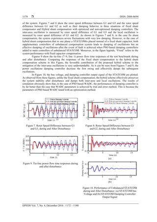
The power system adopted for this study is illustrated in Figure 4 [13]-[14] and [17]. It has
originally 15 buses and six machines in three areas. Although this is a test system, it well serves to illustrate
the concept, which remains the same for large systems. To keep the voltage profile of the system constant,
shunt capacitors are installed at buses 7, 9, and 15. For the nonlinear time domain simulation, generators are
modeled in the d-q-o reference frame and transmission lines are represented in the π model. It is worth
mentioning that the dynamics of generator excitation is also considered in the simulation. The comprehensive
data of the power system are given in the Appendix A. For applying the phase imbalanced shunt compensator
in the system, a single phase STATCOM is installed instead of one phase of shunt capacitor that installed on
bus 7 and the STATCOM contribution in the hybrid compensated phase is 0.5 p.u. of the total reactive
compensation. However, the optimal location of reactive power compensator in practical and large power
systems is vital point and requires comprehensive studies [21].
The power system under study has five distinct oscillatory modes: three local modes and two
inter-area modes which have been obtained by the Eigen value analysis. The inter-area mode 1 is
characterized by having a slightly higher frequency (0.78 Hz) than mode 2 (0.46 Hz). Mode 1 consists of
generators of area 1 swinging against those of area 3. While, mode 2 consists of generators of area 2
oscillating against those of areas 1 and 3 [14]. As a result, in order to mitigate the unstable oscillation modes,
a PSO-based is designed and added to the main control loop of the unbalanced STATCOM.
Figure 4. Three-Area Six-Machine Power System Aggregated with an Unbalanced STATCOM
4. POWER OSCILLATIONS DAMPING CONTROLLER DESIGN
As explained in Section III, the system under study has five distinct modes. These oscillatory modes
are to be damped by an auxiliary damping controller that is added to the main control loop of the unbalanced
STATCOM. Among crucial requirements of implementing auxiliary damping controllers is figuring out its
best location. This task should be done with two major objectives: (i) providing an effective damping of
oscillations and (ii) minimizing the possible interactions between STATCOM reactive power and damping
controllers.
One of the fundamental issues in designing the damping controller is the selection of feedback
signals to achieve the best modal observability and optimal oscillation damping [22]. Any kind of input
signal with sufficient modal observability of inter-area oscillation can be used; amongst are the active power
of tie lines, voltage angle differences between areas, rotor angular speed differences between generators, etc.
Generally, the damping controller input signals can be classified in twofold groups: local signals and wide-
area ones. As a result, two sorts of solutions exist for designing damping controllers: the decentralized
approach based on local signals and the centralized approach exploiting wide-area information. The main
advantage of the former solution comes from the fact that no telecommunication infrastructure is needed. The
expense of this method is that it will suffice to economically and efficiently satisfy the damping requirements
of the present/future heavily stressed networks with credible inter-area oscillation modes. In contrast, the
centralized technique offers more effective outcomes at the expense of having fast communication
infrastructure. Clearly, in a practical environment, selection of either centralized or decentralized solution
depends on a given power system characteristics and its communication facilities. With respect to Figure 4
the power system under study equipped with PMUs, wide area signals used as damping controller input
5. ISSN: 2088-8694
IJPEDS Vol. 7, No. 4, December 2016 : 1172 – 1180
1176
signal. Opposite to the conventional measurement devices, PMUs are synchronized respect to each other
through the one pulse per second signals of the global positioning system. This new opportunity realized the
true concept of measuring phase angles which inherently encompass valuable information of the system
stress situation. The huge infrastructure which is in charge for gathering the PMUs’ data in a central
location(s) is referred to as WAMS. Autonomous control including oscillation damping is among advanced
functionalities imagined for WAMS. Clearly, the WAMS potential in feeding WADCs is directly dependent
to the number and location of PMUs deployed in the grid. The PMU placement problem is a broadly
investigated research area and various aspects of this problem have been so far digested in dept [23]-[25].
Intuitively, it can be deduced that for oscillation damping objective a limited number, but geographically
distributed, of PMUs would work sufficiently. The numerical studies presented in the following support this
conclusion.
One of the main advantages of WADCs is its capability in designing multi-band damping
controllers. Each band of the WADC has its own global input signal for damping one of the oscillation
modes. As the system under study has two inter-area modes, a simple two-band classic controller is
considered which is represented in Figure 5. Each controller is a conventional damping controller that is
shown in Figure 6. Band controllers are denoted by WADC1 and WADC2 and the whole unit is recognized
by WADC.
+
WADC1
3113
WADC2
5115
++
1W
2W
1SignalDamping
2SignalDamping SignalDamping
Figure 5. The Two-Band WADC Designed for the Three-Area Power System
sT1
sT
w
w
sT
sT
4
3
1
1
K
max
min
SignalInput 1SignalDamping
sT1
sT1
2
1
Figure 6. The Block Diagram of the Classical Damping Controller
It is apparent that to damp out multi-mode oscillations, two suitable supplementary signals
containing both modes of oscillations are necessary. Any kind of input signal that has a good modal
observability of inter-area oscillation can be used such as the power of tie line interconnecting two areas,
frequency difference between two areas, angle difference of two buses in two areas, etc.
Generally, the PMU firstly receives the sinusoidal waveforms of three-phase voltages and currents,
then converts the sampled digital data to the phasor values, and finally sends the information to the regional
or system control center [26]. Although the PMU computed frequency and its rate of change are based on
local voltage measurements, there are several approaches to calculate the generator speed through local PMU
measurement [27]-[29]. Frequency is a key indicator for the system stability and generation/demand balance.
This parameter or its derivatives such as rotor speeds and their rates of change are usually implemented as the
damping controller feedback signal [11]-[12] and [17]. To this end, high voltage buses associated with G1,
G3 and G5 are assumed to be equipped with PMUs and 3113 - and 5115 - are chosen
as global feedback signals. For damping the inter-area mode 1 (0.78 Hz), WADC1 is used whose input is
15 and WADC2 is responsible for damping the oscillation mode 2 (0.46 Hz) with input of 13 . As shown
in Figure 5, the output of WADCs are weighted and summed up to generate the WADC output, which is
)2(*)1(* 21 SignalDampingWSignalDampingWSignalDamping (4)
6. IJPEDS ISSN: 2088-8694
Inter-Area Oscillation Damping using an STATCOM Based Hybrid Shunt … (Vahid Farzam)
1177
W1 and W2 are weighting factors and are chosen inversely proportional to the normalized damping
ratio of their dominant mode obtained from the Prony analysis (W1=1.15, W2=1) [14]. The WADC output is
finally employed for modulating the reactive power loop of the STATCOM (see Figure 1).
It has to be noted that the communication system is thus far assumed to be delay free in the design
process which is not the case in real world observations and the communication latency should be considered
in design procedure. The authors intend to work on this issue in future while many good pioneer research is
available presently [18] and the controller designed in this paper is an ideal WADC without considering
latency in wide area signals. The proposed WADC is implemented in the simulation setup and its parameters
are tuned through the PSO technique. İn the following a quiet explanation about optimisation of WADC
parameters has been presented.
4.1. PSO Algorithm
In the PSO technique, there are some simple entities (particle) which their trajectory in the search
space can be adjusted by dynamically regulating the velocity of each particle. Generally, a predefined
objective function will be defined by the user, and then the best value of the objective function that is
achieved by the ith
particle is expressed as Pbest. Furthermore, the overall best value of the objective function
obtained by the particles at every time step (gbest) is calculated through the algorithm. Then, each particle’s
velocity and position is being updated by [18]-[19]:
))(())(()()1( 2211 tXPrctXPrctwVtV idgdidididid (5)
)()1()( tcVtXtX ididid
(6)
Where, Vid is the velocity of the ith
particle, Xidis the position of the ith
particle, Pidand Pgd are Pbest
and gbest, respectively. c1 andc2 are positive constants which are responsible for alternation of the particle
velocity toward Pbest and gbest, r1 and r2are two random constants between 0 and 1 and c is a factor which
can modify the velocity of the particle to adjust the position of each particle in the next iteration. w, inertia
weight, is defined to balance the local and global searches. Hence, the PSO algorithm searches for the
optimal minimum value of the objective function and updates the velocity and particle’s location in each
iteration. The iterative process will be terminated when the stopping criterion is met.
If the parameters of damping controller are properly optimized, the damping of oscillation will be
resulted effectively. For this reason, damping controller parameters will be optimized by the PSO algorithm.
In this study, the objective function to be minimized by PSO is come from the generators rotor speed
deviations. This objective function is an integral of time multiplied by the absolute value of the power
deviation, that is
dtWtJ
simt
13..
0
(7)
Where, simt is the total simulation time and 13W is the generators rotor speed deviations. The
optimization is subjected to parameter limits, i.e.
maxmin KKK , max11min1 TTT , max22min2 TTT , max33min3 TTT , max44min4 TTT
It has to be pointed out that the above parameters are associated with the damping controller
and would be introduced in the next section. Here, the ranges for parameters are as follows. K [0.01-40]
and T1, T2, T3, T4[0.0001-2]. Associated with PSO algorithm, the number of particles, number of iterations,
c1, c2, c, and w are set to 50, 200, 2, 2, 1, and 0.85, respectively and the final values of parameters are
presented in Appendix B.
5. SIMULATION RESULTS
This section demonstrates the capability of the proposed STATCOM based hybrid shunt
compensation scheme in damping inter-area oscillations. As seen on Figure 4, for this propose fixed
capacitor of one phase installed on bus 7 is replaced with an unbalanced. The parameters of the unbalanced
STATCOM are shown in appendix C. For the sake of simulation, it is assumed that in the system shown in
Figure 4, a three-phase to ground fault occurs on bus 8 and lasts for 200 ms. this fault stimulates oscillation
7. ISSN: 2088-8694
IJPEDS Vol. 7, No. 4, December 2016 : 1172 – 1180
1178
of the system. Figures 7 and 8 show the rotor speed difference between G1 and G3 and the rotor speed
difference between G1 and G2 as well as their damping behavior in three situations of fixed shunt
compensator and Hybrid shunt compensation with optimized and non-optimised damping controllers. The
inter-area oscillation is measured by rotor speed difference of G1 and G3 and the local oscillation is
measured by rotor speed difference of G1 and G2. As shown in Figures 7 and 8, in the case fix shunt
compensation, the system experiences severe fluctuations with very low damping. However, in the case of
hybrid shunt compensation that in one phase a STATCOMis placed instead of a fixed shunt capacitor, both
supplementary controllers of unbalanced compensation system leads to damping of oscillations but an
effective damping of oscillations after the event of fault is achieved when PSO based damping controlleris
added to main controllers of unbalanced STATCOM. Moreover, in the figure legends, “Fixed” refers to the
system performance with fixed capacitor compensation.
Figures 9 show the tie-line (7–9, line 1) power flow time responses of the test benchmark during
and after disturbance. Comparing the responses of the fixed shunt compensation to the hybrid shunt
compensation scheme in this Figure, the favorable contribution of the proposed hybrid scheme to the
mitigation of the inter-area oscillations is very understandable. As it can be seen from Figures 7 and 9, the
power oscillations damping controller decrease the first swing and effectively damps the subsequent
oscillations.
In Figure 10, the bus voltage, and damping controller output signal of the STATCOM are plotted.
As observed from these figures, unlike the fixed shunt compensation, the hybrid scheme effectively preserves
the system stability after disturbance and damps both inter-area and local oscillations. The results of
simulation obviously show that, in the case of PSO based WADC, the performances of damping controller is
by far better than the case that WADC parameters is achieved by trial and error method. This is because the
parameters of PSO based WADC tuned with an optimization method.
Figure 7. Rotor Speed Difference between G1
and G3, during and After Disturbance
Figure 8. Rotor Speed Difference between G1
and G2, during and After Disturbance
Figure 9. Tie-line power flow time responses during
and after disturbance
(a)
(b)
Figure 10. Performance of Unbalanced STATCOM
during and After Disturbance: (a) STATCOM bus
Voltage and (b) STATCOM Damping Controller
Output Signal
0 5 10 15
-2
0
2
x 10
-3
time (s)
W1-W2(p.u)
Without Damping Controller
With non-optomised Damping Controller
With PSO Based Damping Controller
0 5 10 15
0.9
1
1.1
time (s)
Vstatcom(p.u)
0 5 10 15
-0.2
0
0.2
time (s)
DampingSignal(p.u)
8. IJPEDS ISSN: 2088-8694
Inter-Area Oscillation Damping using an STATCOM Based Hybrid Shunt … (Vahid Farzam)
1179
6. CONCLOSION
This work is mainly dedicated to investigate the capability of a new “hybrid” shunt compensation
schemes in damping inter-area oscillations. The presented hybrid shunt compensation schemes is easily
achievable, technically sound, and have an industrial application potential. A six-machine three area power
system is put under investigation in order to verify the proposed scheme capability on inter-area oscillation
damping. The power system dynamic stability enhancement achieved by adding two wide area, damping
controllers. A non-optimized conventional damping controller and a conventional damping controller with optomised
parameters. The PSO algorithm is used to solve optimization problem. Both damping controllers are added to
the main control loop of the proposed shunt compensator. With respect simulation illustrations, it was
observed that as the time goes on, the proposed hybrid compensation equipped with auxiliary damping
controller would damp all inter-area and locally oscillation modes; also the results of simulation showed that,
in the case of PSO based WADC, the performances of damping controller was by far better than the case that
WADC parameters were achieved by trial and error method.Hence, the effective performance of proposed
unbalanced shunt compensation in the system oscillation damping was validated.
Appendix A Power System Data
Generator Data: 900 MVA, 20 kV, ra = 0.0025 p.u., xl= 0.2 p.u., xd = 1.8 p.u., xq = 1.7 p.u., x׳d = 0.3
p.u., x׳q = 0.55 p.u., x״d = -0.25 p.u., x״q = 0.25 p.u., T׳
do = 8 s, T״do = 0.03 s, T׳qo = 0.4 s, T״qo = 0.05 s,
H(G1&G2) = 6.5 s, H(G3&G4) = 6.175 s, H (G5) = 5.5 s, H(G6) = 5 s.
Generator Steady State Data: G1: V = 1.04 ∟0o
p.u., G2: P = 700 MW, V = 1.01 p.u., G5: P = 800
MW, V = 1.02 p.u., G6: P = 780 MW, V = 1.01 p.u. Transmission Line Data: r = 0.053 Ω/km, Xseries = 0.53
Ω/km, Yshunt = 5.21 μS/km. Bus 7 load: 1400 + j100-j350, Bus 9 load: 1800 + j100 – j500, Bus 15 load:
1200 + j300 – j220.
Appendix B
Table 1. Parameters of the STATCOM based WADCs
Type K TW T1 T2 T3 T4 min & max
WADC1 9 2 0.012 0.89 1.11 0.011 ±0.2
WADC2 16 2 0.032 1.3 0.014 0.044 ±0.2
Appendix C STATCOM Data
Rated Power = 25 MVA, Rated Voltage = 26 KV, Frequency = 60 Hz, XT(sh) = 0.1 p.u. Switching
Frequency = 15KHz.
REFERENCES
[1] Yu YN. Electric power system dynamics. New York: Academic Press; 1983.
[2] Sauer PW, Pai MA. Power system dynamics and stability. Englewood Cliffs, NJ: Prentice-Hall; 1998.
[3] X. Yang and A. Feliachi, “Stabilization of inter-area oscillation modes through excitation systems”, IEEE Trans.
Power Syst., vol. 9, no. 1, pp.494–502, Feb. 1994.
[4] R.M. Mathur and R.K.Varma, Thyristor-Based FACTS Controllers for Electrical Transmission Systems. New York:
IEEE Press and Wiley.Interscience, Feb. 2002.
[5] N.G. Hingorani, Flexible AC transmission, IEEE Spectrum (1993) 40 45.
[6] E.V. Larson, J.J. Sanchez Gasca, J.H. Chow, “Concepts for design of FACTS controllers to damp power swings”,
IEEE Trans. Power Syst., vol. 10, no. 2, pp948-956, May. 1995.
[7] R. Kunamneni, S. Suman, M. Rambabu, K. Ashok Kumar, "Implementation of phase imbalance scheme for
stabilizing torsional oscillations", International Journal of Electrical and Computer Engineering (IJECE), vol. 4,
no. 5, pp. 697–702, October 2014.
[8] M. Farsadi, A. Ghasemi, B. Ghasemi, " WAMS-Based SSR Damping controller design for FACTS devices and
investigating effects of communication delays", International Journal of Power Electronics and Drive System
(IJPEDS), vol. 6, no. 4, pp. 736–746, December 2015.
[9] D. Divan et al, “A distributed static series compensator system for realizing active power flow control on existing
power lines”, IEEE Trans. Power Delivery, vol. 22, no. 1, pp. 642-649, Jan 2007.
[10] Z. Yuan, S.W.H. de Haan, J.B. Ferreira, and D. Cvoric, “A FACTS Device: Distributed Power-Flow Controller
(DPFC)”, IEEE Trans. Power Electron, vol. 25, no. 10, Oct 2010.
[11] J. Khazaie, M. Mokhtari, M. Khalilian, D. Nazarpour, “Sub-Synchronous Resonance Damping Using Distributed
Static Series Compensator Enhanced with Fuzzy Logic Controller”, Inter Jour of Elect Power and Ener Systems,
vol. 43, no. 1, pp. 80-89, Dec 2012.
9. ISSN: 2088-8694
IJPEDS Vol. 7, No. 4, December 2016 : 1172 – 1180
1180
[12] M. Khalilian, M. Mokhtari, S. Golshannavaz, D. Nazarpour, “Distributed Static Series Compensator (DSSC) for
Subsynchronous Resonance Alleviation and Power Oscillation Damping”, Euro. Trans. Electr. Power, vol. 22, no.
5, pp. 589-600, July 2012.
[13] D. Rai, G. Ramakrishna, S.O. Faried, and A. Edris, “Enhancement of power system dynamics using a phase
imbalanced series compensation scheme”, IEEE Trans. Power Syst., vol. 25, no. 2, pp. 966–974, May 2010.
[14] D. Rai, G. Ramakrishna, S.O. Faried, G. Ramakrishna, and A. Edris, “Damping Inter-Area Oscillations Using
Phase Imbalanced Series Compensation Schemes”, IEEE Trans. Power Syst., vol. 26, no. 3, pp. 1756-1761, Aug
2011.
[15] D. Rai, S. O. Faried, G. Ramakrishna, and A. Edris, “Hybrid series compensation scheme capable of damping
subsynchronous resonance”, Proc. Inst. Eng. Technol. Gen., Transm. Distrib, vol. 4, no. 3, pp. 456–466, March
2010.
[16] X. Xie, J. Xiao, C. Lu, and Y. Han, “Wide-area stability control for damping interarea oscillations of
interconnected power systems”, IET Gen. Transm. Distrib., vol. 153, pp. 507–514, Sep. 2006.
[17] M. Mokhtari, F. Aminifar, D. Nazarpour, and S. Golshannavaz, “Widearea power oscillation damping with a Fuzzy
controller compensating the continuous communication delays”, IEEE Trans. Power Syst., vol. 28, no. 2, pp. 1997–
2005, May 2013.
[18] Ho SL, Yang S, Ni G, Lo EWC, Wong HC. A particle swarm optimization basedbmethod for multi objective
design optimizations. IEEE Trans Magnet, 2005; 41(5): 1756–9.
[19] Shayeghi H, Shayanfar HA, Jalilzadeh S, Safari A. Design of output feedback UPFC controllers for damping of
electromechanical oscillations using PSO. Energy Convers Manage, 2009; 50: 2559–61.
[20] T.J.E Miller, Reactive Power Control in Electric System: [M]. New York, Wiley, 1982.
[21] R. Minguez, F. Milano, R. Zarate-Miano, A.J. Conejo, “Optimal Network Placement of SVC Devices”, IEEE
Trans. Power Syst., vol. 22, no. 4, pp. 1851–1860, Nov 2007.
[22] Farsangi MM, Sung YH, Lee KY. Choice of FACTS Device Control Inputs for Damping Inter-area Oscillations.
IEEE Transactions on Power Systems, 2004; 19(2): 1806–1812.
[23] F. Aminifar, M. Fotuhi-Firuzabad, M. Shahidehpour, and A. Khodaei, “Observability enhancement by optimal
PMU placement considering random power system outages”, Energy Syst., vol. 2, pp. 45–65, Mar. 2011.
[24] F. Aminifar, M. Fotuhi-Firuzabad, A. Safdarian, and M. Shahidehpour, “Observability of hybrid AC/DC power
systems with variablecost PMUs”, IEEE Trans. Power Del., to be published.
[25] F. Aminifar, M. Fotuhi-Firuzabad, and A. Safdarian, “Optimal PMU placement based on probabilistic cost/benefit
analysis”, IEEE Trans.Power Syst., vol. 28, no. 1, pp. 566–567, Feb. 2013.
[26] I. Kamwa and R. Grondin, “PMU configuration for system dynamic performance measurement in large, multi-area
power systems”, IEEETrans. Power Syst., vol. 17, no. 2, pp. 385–394, May 2002.
[27] A. G. Phadke, “Synchronized phasormeasurements in power systems”, IEEE Comput. Appl. Power, vol. 6, pp. 10–
15, Apr. 1993.
[28] K. Mei, S.M. Rovnyak, and C.M. Ong, “Clustering-based dynamic event location using wide-area phasor
measurements”, IEEE Trans.Power Syst., vol. 23, no. 2, pp. 673–679, May 2008.
[29] P. Tripathy, S.C. Srivastava, and S.N. Singh, “A divide-by-differencefilter based algorithm for estimation of
generator rotor angle utilizing synchrophasor measurements”, IEEE Trans. Instrum. Meas., vol. 59, pp. 1562–1570,
Jun. 2010.
BIOGRAPHIES OF AUTHORS
Vahid Farzam was born in Tabriz, Iran, September 1992. He received the B.Sc. and the M.Sc.
degrees in electrical engineering from the Islamic Azad University of Tabriz, Tabriz, Iran, in
2013 and 2016, respectively. His research interests arein advanced power electronic, flexible AC
transmission system (FACTS), power quality, renewable energy, wide area measurement system,
and power system dynamics.
Ahad Mokhtarpour was born in Tabriz, Iran, 1979. He received the B.S. degree from University
of Tabriz, Tabriz, Iran, M.S.E. degree from Iran University of Science and Technology, Tehran,
Iran and Ph.D degree from Islamic Azad University, Science and Research Branch, Tehran, Iran
all in Electrical Engineering in 2003, 2005 and 2013, respectively. Currently he is with
Departement of Electrical and Computer Engineering,Tabriz Branch, Islamic Azad University
Tabriz, Iran as an Assistant Professor. His research interests are in the power quality
compensation, FACTS device, distribution network control and reliability.