
More Related Content
What's hot
What's hot (20)
Similar to Estimation & costing guide
Similar to Estimation & costing guide (20)
Recently uploaded
Recently uploaded (20)
Estimation & costing guide
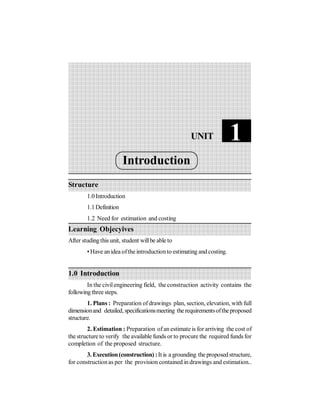
- 1. Structure 1.0Introduction 1.1Definition 1.2 Need for estimation and costing Learning Objecyives After studingthis unit, student willbe able to • Have anidea ofthe introductionto estimating and costing. 1.0 Introduction In the civilengineering field, the construction activity contains the following three steps. 1. Plans : Preparation ofdrawings plan, section, elevation, with full dimensionand detailed, specificationsmeeting therequirementsoftheproposed structure. 2. Estimation : Preparation ofan estimate is for arriving the cost of the structure to verify the available funds or to procure the required funds for completion of the proposed structure. 3. Execution(construction) :It is a grounding theproposedstructure, for constructionas per the provision contained in drawings and estimation.. Introduction 1 UNIT
- 2. Construction Technology 152 The plans contains size of roomand dimensions ofthe work and the estimate contains the quantity and quality aspects ofthe structure. 1.1 Definition Estimation and costing there are two basic points involved in constructionofstructures are : 1. Quantity: Thequantity aspectsiswith referencetothemeasurement in thedrawings (plan, elevation, section) 2. Quality: Thequalityaspectsis with reference to the specifications, i.e properties ofmaterials, workmanship etc. Note : The estimation and costing ofanystructure is defined as the process of determination of quantities of items of work, and its cost for completion. 2. Estimate ofa project is therefore, a forecast ofits probable cost. 1.2 Need for Estimation and Costing The object ofpreparing the estimatefor anycivilengineering structure is 1. To know the quantities ofvarious items of work, a materialand labour and theirsource ofidentification. 2. To decide whether the proposalcanmatch the available funds to complete the structure. 3. To obtainthe administrative and technicalsanction ofestimate from the competent authoritiesto release thefundsforconstruction. 4. To invite tenders or quotations based on the estimate quantities for entrust of works to the execution. Short Answer Type Questions 1. What is meant byEstimating and Costing ? 2. Stateneed for Estimationand Costing.
- 3. Structure 2.0 Introduction 2.1 Units ofmeasurements 2.2 Rules For Measurement 2.3 Different methods oftasking out quantities Learning Objectives After the studyingthis unit student willbe able to • To measure various quantities as per rules. 2.0 Introduction The units ofdifferents works depends on their nature, size and shape. .In general, the units of different items of works are based on the following principle. 1. Massive or volumetric items ofwork such asearth work, concerete for foundations, R.R Masonry , Brick Masonry etc. The measurements of length, breadth, height ordepthshallbe takentocomputethe volume or cubical contents. 2. Shallow, thin and surface work shallbe taken in square unit or in area. The measurements of length and breadth or height shall be taken to compute the area, Ex. Plastering, white washing etc. Measurement of Materials and Works 2 UNIT
- 4. Construction Technology 154 3. Long and Thin work shall be taken inlinear or running units and linear measurement shall, be taken. Ex : Fencing, Rainwater pipes, ornamental borders etc. 4. Single units ofwork are expressedinnumbers.Ex. Doors,Windows, Rafters, Trusses etc. 2.1 Units of measurement for various items of Civil Engineering Works Sl.No 1. 2. 3. 4. 5. Unit of payment 10.00cum 1.00cum 1.00rmt 10.00cum 10.00cum 1.00cum 1.00cum 1.00cum 1.00cum Particulars of items (a)Earthworkexcavationinall types of soils except rock re- quiringblastering. (b) Earth work excavation in the soils hard rock requirng blastering. (c) Excavation of pipe line throughofspecified widthand depth inalltypes ofsoils (d) Earthwork for road for- mation ,bund formation etc. cutting , embankment. (e) Refilling of foundations , basements, pipelines, trenches withexcavated soils. Plain cement concrete for foundation. R.R.masonry or brick ma- sonry for foundation base- ment, superstrucrture, parapet walletc. Filling the basement with sand. (a) RCC 1:2: 4 with normal reinforcement forplinthbeam, columns, lintels, verandah beam- T beam etc. Units of measure- ments 10.00cum 1.00cum 1.00 rmt 10.00cum 10.00cum 1.00cum 1.00cum 1.00cum 1.00cum
- 5. Paper - II Estimating and Costing 155 10.00sqm 10.00sqm 10.00sq m. 1.00Rmt 1.00No 1.00No 1.00Rmt 1.00Rmt kg/unit 1.00cum 1.00cum 1.00sqm 1.00cum 6. 7. 8. 9. 10 11. 12. 13. 14. 15. (b) R.C.C 1: 2: 4 for slabs of specified thickness . Plastering pointing, flooring, weather proof coarse, white washing,colourwashing,paint- ing. Roofing withA.C sheets, tiled roofing, Kurnooltrerrace, Ma- dras terrace etc. D.P.C specified width and thick- ness Wooden and steel trusses Doors, windows, ventilators. Ornamentelborder of speci- fied widthand thickness. R.C.C pipes, A.C pipes GI or C.I pipes, stone ware pipes etc. Steelreinforcement inR.C.C. Rough stone pitching revet- ment and soiling of specified thickness. (a) Roads works : Metal col- lections , gravel collections, solving stones, pitching any stones, revetment stones etc. (b) Road works : Spreading metalgraveland consolidation with roller ofspecified thick- ness. (c) Cement concrete pay- ments ofspecified thickness. 10.00sqm 1.0.00sqm1.00sqm 10.00sq m. 1.00Rmt 1.00No 1.00 No 1.00Rmt 1.00Rmt Kg/unit 1.00cum 1.00cum 10.00sqm 10.00cum
- 6. Construction Technology 156 2.2 Rules For Measurement Measurement ofworks occupiesaveryimportant placeintheplanning and execution ofanywork or project, fromthe time ofthe first estimate are madeuntilthe completion and settlement ofpayments. The methods followed for the measurement are not uiform and the practices or prevalent differ considerablyinbetweenthe states. Eveninthe samestatedifferent departments followdifferent methods. Forconvernienceauniformmethodshould befollowed throughout the country. The uniform methods ofmeasurement to be followed which is applicable to the preparation of the estimates and billofquantities and to theside measurement ofcompleted works have beendescribed below. General Rules 1. Measuremet shallbe itemwise forthe finished items ofwork and the descriptionofeachitemsshall be held toinculde materials, transport, labour, fabrication, hoisting, tools and plants, over hands and other incidentalcharges forfinishing the work to therequired shape, size, designand specifications. 2. In booking dimensions the order shallbe in the sequence oflength, breadth and height or depth or thickness. 3.Allworksshallbemeasured not subject to following tolerances unless otherwise stated. (a) Dimensions shallbe measured to the nearest 0.01 meter i.e 1cm(1/ 211 ). (b)Areas shall eb measured to the nearest 0.01 sq.m(0.1 sqft). (c) Cubiccontents shallbe workedup to the nearest 0.01 cum(0.1cuft) 4. Same type of work under different condition and nature shallbe measured separatelyunder separate items. 5. The billofquantities shallfullydescribe thematerials proportions andwork-manships andaccuratelyrepresent theworktobe executed. Work which byits nature cannot be accuratelytaken offor which requires site measuremets shallbe described as provisional. 6. In case of structurealconcrete, brick work or stone masonry, the work under the following categories shall be measured separately and the heights shallbe described. (a) Fromfirst floor level
- 7. Paper - II Estimating and Costing 157 (b) Fromplinth levelto first floor level. (c) Fromfirst levelto second floor level and so on. The parapet shall be measured with the corresponding items of the storynext below. Principle ofunits:Theunitsofdifferent worksdependontheir nature, size and shape. In generalthe units ofdifferent itemofwork are based onthe following principle. (i) Mass, voluminious and thick works shallbe taken in cabic unit or volumne. The measurement of length, breadth, and height or depth shall be taken to compute the volume cubic contents(cum). (ii) Shallow, thin and surface work shallbe taken in separate units or in area. The measurement of length and breadth or height shall be taken to compute the area (sq.m). (iii) Long and thin work shall be taken in linear or running unit and linear measurement shallbe taken(running meter). (iv) Piece work, job work etc taken in number 2.3 Different methods of taking out quantities Theitems ofworklikeearthworkinexcavation infoundation,foundation concrete stonemasonryinfoundationand basement, stone or brick masonryin super stucrture maybyestimated bu either ofthe following methods. 1. Long wall and short wallmethod (or) Generalmethod 2. Centreline method 2.3.1 Long wall and short wall method Inthis methodmeasure orfind out the external lengthsofwalls running in the directiongenerallythe long walls out-to-out and the internal length of walls runningin the transverse direction in-to-in i.e. ofcross or short wallin- to-inand calculatequantities multiplying the lengthbythe breadthand height of wall. The same rule applicable to the excavation in foundation, to concrete in foundaiuonandto masonry. The simple mehtod is to take the long walls of short or erros walls separately and to find out the centre to centre lengths of long wall anf short walls from the plan. For symmetrical footing on either sides, the centre line remians same for suepr structure and for foundation and plinth.
- 8. Construction Technology 158 For long walls add to the center length one breadth of wall, which givesthelengthofthe wallout-to-out ,multiplying thislengthbythebreadthand height and get the quantities,. Thusfor findingthe quantities ofearthwork in excavation, for the length of trench out-to-out add to the centre length one breadthoffoundaiton.Adopt the sameprocess for foudationconceret and for eacth footing. It should be notedthat eachfooting isto be taken separately and the breadthofthe particular footing is to be added to the centre length. Long walllengthout-to-out = centreto centre length+ halfbreadth on oneside+halfbreadthon the other side =centre to centrelength+ onebreadth. For short or cross walls subtract ( instead ofadding) from the centre lengthonebreadthofwall, which givesthe lengthin-to-in, and repeat the same process as for the long walls, subtracting one breadthinstead ofadding. Short walllengthin-to-in= Centre to centre length- one breadth. That is, in case of long wall add one breadth and in case ofshort wall substract one breadth fromthe centre lengthto get the corresponding lengths. It willbe noticed that bytaking dimensions in this ways, the long walls are graduallydecreasingin length fromfoundationto superstructure, while the short walls areincreasing inlength. Thismethodissimpleandaccurateandthereisno chanceofanymistake. This method may be named as long wall and short wall method, or general method. 2.3.2 Centre line method In this method known as centre line method. This method is easy and quick incalculations. Inthis method sumtotallengthofcentre lines ofallwalls, long and short has to be found out. This method is well suitable for walls of similar cross sections. Inthis method the totalcentre line multiplied bybreadth and depthofconcerned itemgivesthetotalquantityofeachitem.Inthismethod, thelengthwillremainsameforexcavationinfoundationforconcreteinfoundation, for allfootings and for super structure (with slight difference where there are crosswallsornumberofjunctions).It requiresspecialattentionandconsideration at the junctions, meeting points ofpartition or cross walls, etc. For rectangular, circular polygonal(hexagonal, octagonaletc) building havingno interor cross walls, thismethod isquite simple. Foreachjunctionhalf breadth of the respective items or footings is to be deducted from the total centre length. Thus inthe caseofa building withone partitionwallorcross wall havingtwo junctions,forearthworkinfoundationtrenchandfoundationconcrete deduct onebreadthoftrenchorconcretefromthetotalcentrelength(halfbreadth
- 9. Paper - II Estimating and Costing 159 for onejunctionand thebreadth( 2 x1/2= one) for twojunctions. Forfootings, similarlydeduct one breadth offootingfor two junctions fromthe totalcentre length andso on. Iftwo walls come fromoppositedirections and meet awallat the samepoint, than there willbe two junctions. Inthecaseofabuildinghavingdifferent type ofwalls,suppose the other (main) walls are ofAtype and inter cross walls are ofB type, then allA type walls shall be taken jointly first , and then all B type walls should be taken together separately. Insuch cases no deductions ofanykind need be made for A type walls, but when B type walls are taken, for eachjunction deducting of half breadth ofAtype wall (main wall) shall have to be made from the total centre lengthofwalls. It may be noted that at corners of the building where two walls are meeting no substractionor addition is required. Note:Student shouldpracticemethodIfirstandwhentheyhavebecome sufficientlyacquaintedwithmethod I, thenonlytheyshould takeupthe method II. Short Answer Type Questions 1.Writetheunit ofmeasurements. Earthwork,P.C.C, R.C.C, Masonary, Plastering, Flooring, Fencing, Ornamentalborder, Door, Windows, Trusses etc. 2. Write generalrules for measurement. 3. Write different methods oftaking out quantities and describe.
- 10. Construction Technology 160 Structure 3.0 Introduction 3.1 Detailed estimate 3.2 Preliminaryor approximate estimate 3.3 Problems in preliminaryestimate Learning Objectives After studying this unit student willbe able to • Understand the definition ofdetailed estimate, stages ofpreparation ofestimate, Data required for an estimate and types ofestimate. 3.0 Introduction An estimate is a probable cost ofa work. It is usuallyprepared before the construction is taken up. The primary object of an estimate is to know beforehand the cost ofthe work. The actualcost ofthe work is knownafter the completionofthe work. Iftheestimate is prepared carefullyand correctlythere willnot be muchdifference intheestimated cost and actualcost. The estimator should be fully acquainted with the methods of construction, skilled and experienced foraccurate estimating. 3 UNIT Types of Estimates
- 11. 161 Paper - II Estimating and Costing 3.1 Detailed estimate The estimate maybe approximate or preliminaryestimate or accurate estimate. Inapproximate estimate theapproximatecost ofthe workisestimated. In the accurate estimate the detailsofvarious items are taken and calculated. 3.1.1 Definition The estimate preparedbydividing the work into different items, taking detailed measurements ofeach itemofwork and calculating their quantities is known as detailed estimate. 3.1.2. Stages of preparation To prepare thecompleteestimationofthe project, besidesthe estimated cost ofdifferentmainitemsofwork,Thecost ofpreliminaryworksandsurveying, cost ofland and its acquisition, cost ofleveling and preparationofground and thecostofexternalservices areto be provided. Provisionofsupervisioncharges and contractors profit are to be provided in the estimate. Data required for preparing an estimate : To prepare an estimate for a work the following data are necessary. Drawings: Thedetaileddrawings ofplan, elevationandsection, drawn to a scaleare necessaryto take the details ofmeasurements ofvarious items of work. Specifications : The specifications gives the nature, qualityand class ofmaterials, their proportion, method ofexecution and workmanship and the class oflabourrequired. The cost ofthework varies withits specifications. The cement mortarwith1:3 is morecostlier thancement mortar with 1:6. Rates:Theratesforvariousitemsofwork, theratesofvariousmaterials to be usedinconstruction, the wagesofdifferent categories oflabour should be available for preparinganestimate. The locationofthe work andits distance of source ofmaterials and cost oftransport should be known. Theserates maybe obtained from the Standard Schedule of Rates prepared by the engineering departments. 3.1.3 Detailsof measurements and calculation ofquantities and abstract of estimated cost To prepare an accurate estimate, a detailed estimate ofquantities of various items ofwork and an abstract estimate ofthe quantities and their unit rates are required.
- 12. Construction Technology 162 Detailed Estimate Abstract estimate 3.2. Preliminary or approximate estimate Preliminaryor approximate estimate is requiredfor preliminarystudies ofvarious items ofwork or project , to decide the financialposition and policy foradministrative sanctionbythecompetent authority.Thepreliminaryestimate is prepared by different methods for different types of works. The various methods ofpreparing the preliminaryestimate are plintharea estimate, cubical rate estimate and estimate per unit base. 3.2.1 Plinth area estimate The plintharearateis calculated byfinding the plinthareaofthe building and multiplying by the plinth area rate. The plinth area rate is obtained by comparing thecost ofthecost ofsimilar building havingsimilar specifications in the locality. 3.2.2. Cubic area estimate The cubic rate estimate is prepared on the basis ofthe cubicalcontents ofthebuilding. Thecubic rateis obtained fromthecost ofthe similarbuilding in the localityhaving similar specifications. Thecost ofthe buildingis estimated by multiplyingthevolumeofthebuildingwiththecubicarearate.Cubicrateestimate is more accurate as compared to the plinth area estimate. 3.2.3 Estimate per unit base Thepreliminaryestimate maybe prepared for different structures and works byvarious ways. For schools and hostels, per class rooms for schools, per bed forhospitals, per seat fortheater halls, etc. For roadsand highways and for irrigationworks, the preliminaryestimateismade per kilometer.For bridges and culvertsper running meter. For sewerage and water supplyprojects on the basis ofper head of population served. S.no Description of work No Length Breadth Height/Depth Quantity Remarks S.No. Description of work Quantity Rate Per Amount
- 13. 163 Paper - II Estimating and Costing 3.3. Problems in preliminary estimate 1. Ifthecost ofschoolbuildingper student is Rs. 25000. Calculate the cost ofschoolbuilding for 100 students. Cost of the school building for 100 students = Rs. 25000x100=Rs.2500000. 2. Ifthe cost ofconstruction of1 km. length ofa highwayis Rs. 10000000. Find the cost ofconstructionfor 20 km. Cost ofconstruction for 20 km= Rs. 10000000x20=Rs.200000000. 3. Ifthe plinth area rate ofa residentialbuilding is Rs.10000/sq m. Calculate the cost ofconstruction ofa residentialbuilding of100 sq. m. Cost of construction of 100 sq. m.= plinth area rate x area = 10000x100=Rs.1000000 Summary Detailedestimateconsistsoftakingthedetailedmeasurements oflength, breadth, height andcalculating thequantities. Data required for estimate : Drawings, specifications and rates. Types of preliminary estimates : Plinth area estimate, cubic rate estimate and estimate per unit base. Short Answer Type Questions 1. Define detailed estimate. 2. What are stages for preparation ofan estimate? 3. List out the data required for preparation ofan estimate. 4. Write the tabular formfor the detailed estimate. 5. Write the tabular formfor preparation ofanabstract estimate. Long Answer Type Questions 1. Describe the various typesofpreliminaryestimates.
- 14. Construction Technology 164 Structure 4.0 Introduction 4.1 Single roomed building (loadbearing structure) 4.2 Two roomed building( load bearing type structure) 4.3 Singlestoriedresidentialbuildingwithnumberofrooms(loadbearing type structure) 4.4 Singlestoried residentialbuilding withnumber ofrooms (framed structure type) 4.5 Primaryschoolbuilding withsloped roof 4.6 RCC Dog legged – open wellstairs 4.7 Two storied residentialbuilding (framed structure type) 4.8 Detailed estimate ofcompound walland steps Learning Objectives After studying this unit student willbe able to Prepare detailedestimates ofsingle roomed, Building roomed, Double roomed buildings, forload bearing walls and Framedstructures. Detailed Esti- mateofPrimarySchoolBuilding, Compound walls andsteps. Detailed estimate Dog legged and OpenWellSTair case. Preparationalestimate for ground and first floor. 4 UNIT Detailed and Abstract Estimate of Buildings
- 15. 165 Paper - II Estimating and Costing 4.0 Introduction To estimate the cost of any building or a structure, drawings, specifications and rates are required. Regarding the detailed estimate bylong wallandshort wallmethod and centre line method, the drawings consisting of planelevationandsectionare sufficient. Theestimator should be ableto take all the dimensions from the drawings. The length and breadth are taken fromthe plan, while theheight or deptharetakenfromthe sectionandelevations. Inlong wallandshortwallmethod thewallsaretakenseparately, while inthe centre line method, the centre line lengths ofallthe walls are combined. The accuracyof estimate depends upon the skillofthe estimator in studying the drawings. The long walland short wallmethod is usefulfor load bearing type structure, but it cannot be applied for framed structure. 4.1 Single roomed building (load bearing structure) There are two steps inestimating the cost ofa building or a structure. 1.Takingoutquantities andcalculationofquantitiesindetailedestimate. 2. Determiningthe cost fromthe abstract estimate. Long wall and short wall method : This method is also called as separate orindividualwallmethod. Thisis simple and it gives accurate values. The following procedure is adopted. 1.Thedimensionsoflongwallandshort wallshouldbetakenseparately. 2. Irrespective ofitslengths, thewallwhichistakenfirst islong walland the wallwhichis taken next is the short wall. 3. Thecentrelineofthewallofthebuildingisconsideredfordetermining the centre to centre line length oflong walls and short walls. 4. The centre to centreto centre lengthoflong walls or short walls is obtained byadding halfthe width ofthe wallto theinternallength of either long wallor short wall. 5. Centreto centre lengthoflong wall=internallengthoflongwall+ ½ width ofthe wall. 6. Centre to centre lengthofshort wall=internallengthofshort wall+ ½ widthof the wall. 7. To determinethe lengths ofdifferent quantities such as earthwork, c.c. bedinfoundation, R.R. masonryetc, lengthoflongwall= centre
- 16. Construction Technology 166 to centre lengthoflong wall+ width, the widthis the respective width ofthe itemin consideration. 8. Similarlylengthoftheshort wall=centreto centrelengthofthe short wall – width, where the widthis the respective widthofthe item such as earthwork, c.c. bed etc. Centre line method : In the centre line method, the sum of all the centre linelengths oflong wallsand short walls areadded to get thetotalcentre line length. At the junctions of two walls, the length is present in both of the walls. Hence halfofthe lengthofthat width is to be subtracted fromthe total centrelinelength. Length =Totalcentre line length– ½ widthxnumber ofjunctions. Fig 4.1 Plan Single Room Centre to centre length oflong wall= 6.0 + 2x0.3/2 = 6.3 m. Centre to centre length ofshort wall= 4.0 + 2x0.3/2 = 4.3 m. Length ofLongWall= Centre to centre Length ofLongWall+Width Length ofShort Wall= Centre to centre Length ofShort Wall– width For earthwork inexcavation LengthofLongWall= 6.3 + 1.2 =7.5 m. E L E V A T I O N S E C T I O N 1.2 0.9 0.7 0.5 0.3 0.6 0.3 3.0
- 17. 167 Paper - II Estimating and Costing For earthwork inexcavationLengthofShort Wall=4.3 – 1.2 =3.1 m. In cement concrete in foundation the length and widthofthe long wall and shortwallare thesame, but theheight isdifferent fromthat ofthe foundation For R.R. masonryFirst footing Lengthoflong wall=6.3 + 0.9 =7.2 m. Length of Short Wall= 4.3 -0.9 = 3.4 m. Similarlyfor secondfooting &Thirdfooting,LengthofLongWalls are 7.0 and 6.8 and for short walls are 3.6 m and 3.8 m respectively. Detailed estimate ofa single roomed building bycentre line method Centre to centre length oflong wall= 6.0 + 2x0.3/2 = 6.3 m. Centre to centre length ofshort wall= 4.0 + 2x0.3/2 = 4.3 m. Totalcentre line length = 2(6.3 + 4.3) = 21.2 m. Detailed Estimate Quantity 30.528 7.63 11.45 4.45 12.72 28.62 19.08 Remarks Sl. No. 1 2 3 4 Description of work Earth work in excavation C.C. bed in foundation R.R. masonry infoundation and plinth First footing Secondfooting Basement Brick work in superstructure No. 1 1 1 1 1 1 L 21.2 21.2 21.2 21.2 21.2 21.2 B 1.2 1.2 0.9 0.7 0.5 0.3 H 1.2 0.3 0.6 0.3 1.2 3 m m m m3
- 18. Construction Technology 168 Sl. No. 1 2 3 Description of work Earthwork in excavationin foundation Long Walls Short Walls Plaincement concrete infoundation(1:5:10) Long Walls Short Walls R.R. Masonryin foundation & basement c.m(1:8) First footing Long Walls Short WaLLS Secondfooting Long Walls Short WaLLS Basement Long Walls Short Walls No. 2 2 2 2 2 2 2 2 2 2 L m 7.5 3.1 7.5 3.1 7.2 3.4 7 3.6 6.8 3.8 B m 1.2 1.2 1.2 1.2 0.9 0.9 0.7 0.7 0.5 0.5 H m 1.2 1.2 Total 0.3 0.3 Total 0.6 0.6 0.3 0.3 1.2 1.2 Quantity m3 21.6 8.93 30.53 5.4 2.68 8.08 7.78 3.67 11.45 2.94 1.51 4.45 8.16 4.56 Remarks L=6.3+1.2=7.5 L = 4 . 3 - 1.2=3.1 L=6.3+1.2=7.5 L = 4 . 3 - 1.2=3.1 L=6.3+0.9=7.2 L = 4 . 3 - 0.9=3.4 L=6.3+0.7=7.0 L = 4 . 3 - 0.7=3.6 L=6.3+0.5=6.8 L = 4 . 3 - 0.5=3.8
- 19. 169 Paper - II Estimating and Costing 4.2 Two roomed building( load bearing type structure) Detailed Estimate OfADouble Roomed Building ByLong WallAnd Short WallMethod Centre to centre length oflong wall= 5.0 + 0.3 + 5.0 + 2x0.3/2 = 10.6 m. Centre to centre length ofshort wall= 5.0 + 2x0.3/2 = 5.3 m. Number oflong walls = 2. Number of short walls = 3. Lengthoflongwall= centre to centre lengthoflong walls + width Length ofshort wall= centre to centre lengthofshort wall- width 4 Brick work insuper structure c.m. ( 1:8) Long Walls Short Walls 2 2 Total of 6.6 4 R.R. 0.3 0.3 masonry 3 3 12.72 28.62 11.88 7.2 19.08 L=6.3+0.3=6.6 L = 4 . 3 - 0.3=4.0 Sl. No. 1 2 Description of work Earthworkin excavation Long Walls Short Walls C.C. bed in foundation Long Walls No. 2 3 2 L m 11.8 4.1 11.8 B m 1.2 1.2 1.2 H m 1.2 1.2 Total 0.3 Quantity m3 33.98 17.71 51.69 8.5 Remarks L= 10.6 + 1.2 = 11.8 L = 5.3 - 1.2 = 4.1 Totalcentre to centre line lenght = 10.6 x 2 + 5.3x3 = 37.1 m
- 20. Construction Technology 170 3 4 Short Walls R.R. masonryin foundation& plinth First footing Long Walls Short walls Secondfooting Long Walls Short Walls Thirdfooting& plinth Long Walls Short walls Brick work in super structure Long Walls Short Walls 3 2 3 2 3 2 3 2 3 4.1 11.5 4.4 11.3 4.6 11.1 4.8 10.9 5 1.2 0.9 0.9 0.7 0.7 0.5 0.5 0.3 0.3 0.3 0.6 0.6 0.3 0.3 1.2 1.2 3 3 4.43 12.93 312.42 7.13 19.55 4.75 2.9 7.65 13.32 8.64 21.96 49.16 19.62 13.5 33.12 L = 10.6 + 0.9 = 11.5 L = 5.3 - 0.9 = 4.4 L = 10.6 + 0.7 = 11.3 L = 5.3 -0.7 = 4.6 L = 10.6 + 0.5 = 11.1 L = 5.3 - 0.5 = 4.8 L= 10.6+ 0.3= 10.9 L = 5.3 - 0.3 = 5.0 R.R. masonryTotal
- 21. 171 Paper - II Estimating and Costing Centre line method Fig 4.2 Double Room No. 1 1 1 1 1 1 1 L 35.9 35.9 36.2 36.4 36.6 36.8 B 1.2 1.2 0.9 0.7 0.5 0.3 H 1.2 0.3 0.6 0.3 1.2 Total 3 Sl. No. 1 2 3 4 Description of work Earthworkin excavation C.C. bed in foundation R.R. masonryin foundation First footing Secondfooting Basement Brickwork in superstructure Remarks L= 37.1 - 2x1/2x1.2 L = 37.1 - 2x1/2x0.9 L = 37.1 - 2x1/2x0.7 L = 37.1 - 2x1/2x0.5 L = 37.1 - 2x1/2x0.3 Quantity 51.69 m3 12.93 m3 19.55 me 7.65 m3 21.96 m3 49.165 m3 33.12 m3 E L E V A T I O N S E C T I O N 5m x 5 m 5 m x 5 m 1.2 0.9 0.7 0.5 0.3 0.6 0.3 3.0
- 22. Construction Technology 172 4.3 Single storied residential building with number of rooms (load bearingtype structure) Length oflong walls = 6.0+0.3+5.0+2x0.3/2=11.6 m. Number oflong walls = 3 Length ofshort wallof5.0 m. length= 5.0+2x0.3/2=5.3 m. Number of5.0 mshortwalls =3 Length of4.0 m. length short walls = 4.0+2x0.3/2=4.3m. Number of4.0 m. length short walls = 3 Totalcentre line length= 11.6x3+5.3x3+4.3x3=63.6m. Fig 4.3 Plan Section 6.0 x 5.0 m 5.0 x 5.0 m 5.0 x 4.0 m 5.0 x 4.0 m D D D D D D 0.3 0.6 0.3 0.9 0.9 1.2m 3.0m
- 23. 173 Paper - II Estimating and Costing 56.43 m m m m3 5m 4m 5m 4m 5m 4m 5m 4m Basement Basement
- 24. Construction Technology 174 4.4 Single storied residential building with number of rooms (framed structure type) Number ofcolumns in a framed structure = 9 Size ofthe columns = 230mmx230 mm Length of R.R. masonry, Brickwork, lintels, plinth beam and beams under slab = (6+6)x3+(5+4)x3=63 m. Length ofsunshades and externalplastering = (12.9+9.9)x2= 45.6 m. Length ofslab with 1 m. extension on both sides = 1.0+1.0=2.0 m. ExternalPlastering :Area ofexternalplastering =LengthxHeight Length ofPlastering = 2x(12.9+9.9)=45.6 m. Height ofexternal plastering = 3.0+0.12, where 3.0mis the height of the room and 0.12 m. is the thickness ofthe slab. Internalplastering: Area ofinternalplastering = Lengthx Height Length of plastering = 2(L+B) , Where L and B are the length and breadthofthe roomrespectively. For 6mx5mroom, length = 2(6+5)=22m. Similarlyfor 5mx4mroom, length=2(5+4)=18 m. Fig 4.4 Residential Building Framed Structure 6.0x5.0m 5.0x5.0m 5.0x4.0m 6.0x4.0m P L A N S E C T I O N 0.23x0.23 R.C.CColumn 3.0m 1.2m 0.9m 0.3m 0.3m R.C.C. Footing R.C.C. G .L G .L 100 mm thick RCC slab 1.2m
- 25. 175 Paper - II Estimating and Costing B m 1.2 0.9 0.6 1.2 0.9 0.6 0.7 0.45 0.23 0.23 0.23 1.2 0.23 S. No. 1 2 3 4 5 Description of work Earthworkinexcavation Columns Inbetweencolumns Deduct for columns C.C. bed in foundation Columns Inbetweencolumns Deduct for columns R.R. masonryin foundation First footing Secondfooting Brickwork in superstructure Deductions Doors Windows R.C.C. column footing Trapezoidalsection Stem No. 9 1 9 9 1 9 1 1 1 6 8 9 9 9 L m 1.2 63 0.6 1.2 63 0.6 63 63 63 1 1.2 1.2 0.23 H m 1.8 0.9 0.9 0.3 0.3 0.3 0.6 1.2 3 2 1.2 0.3 0.3 5.1 Quantity m3 23.33 51.03 -2.92 71.44 3.89 17.01 -0.972 19.93 26.46 34.02 60.48 43.47 -2.76 -2.65 38.06 3.89 2.44 2.43 8.76 Remarks L=12x3+ 9x3=63 H=0.9+1.2+ 3.0=5.1 Net Brickwork in super structure (1.44+4x0.985+0.053)/6
- 26. Construction Technology 176 6 7 8 9 10 11 R.C.C. Plinth beam R.C.C. in lintels&sunshades Lintels Sunshades R.C.C. slaband beams Beams under slab 1m. Projection from slab R.C.C. Slab. Externalplastering 20 mm Thick Deductions Doors Windows InternalPlastering 12 mmthick Rooms6mx5m Rooms5mx4m Sandfillinginrooms Rooms6mx5m 1 1 1 1 9 1 1 6 8 2 2 2 63 63 45.6 63 1 14.9 45.6 1 1.2 22 18 6 0.23 0.23 0.7 0.23 0.23 11.9 5 0.3 0.1 0.07 0.3 0.3 0.12 3.12 2 1.2 3 3 1.2 4.35 1.45 2.23 3.68 4.35 0.62 21.28 26.25 142.27 -12 -11.52 118.75 132 108 240 72 L=2(12.9+ 9.9)=45.6 L=12.9+1.0+ 1.0=14.9 B=9.9+1.0+ 1.0=11.9 L=2(12.9+9.9) =45.6 H=3.0+0.12 L=2(6+5)=22 L=2(5+4)=18 Net External plastering area
- 27. 177 Paper - II Estimating and Costing 4.5 Primary school building with sloped roof Wallthickness = 0.3 m. inbrick masonry. Width offoundation = 1.2 m. Depth offoundation= 1.8 m. Widthoffirst footing = 0.9 m. Depthoffirst footing = 0.9 m. Second footing width= 0.7 m. Depth = 0.6 m. Width ofthird footing and plinth = 0.5 m. Height = 0.9 m. Centre to centre length oflong walls = 3.0+0.3+3.0+2x0.3/2=6.6 m. Centre to centre length ofshort walls = 3.0+2x0.3/2=3.3 m. Totalcentre line length= 6.6x2+3.3x3=23.1 m. Number ofjunctions = 2. Height ofthesloping roof=1.0 m. 12 13 14 Rooms5mx4m C.C. bed in rooms Rooms6mx5m Rooms5mx4m Flooringinrooms Rooms6mx5m Rooms5mx4m Fabrication & placement of steel 2 2 2 2 2 5 6 5 6 5 4 5 4 5 4 1.2 0.1 0.1 48 120 6 4 10 60 40 100 (8.76+4.35+3.68+26.25)x1.25x87.5/100x1000 78.5x100/100x1000 tonnes 4.22 t
- 28. Construction Technology 178 Length ofthe sloping roof = square root of (1.5mx1.5m+ 1.0m.x1.0 m.) = 1.8 m. Number of gable rafters at a spacing of 30 cms. Centre to centre =( 6.0/0.3)+1=21 Length ofthe gable rafters = 1.8+1.8+0.5+0.5=4.6 m. Number ofreapers along a length of6.05 mts.At a spacing of10 cms each = (4.6/0.1)+1=47
- 29. 179 Paper - II Estimating and Costing ELEVATION W W D D Room 3.0 x 3.0 m Room 3.0 x 3.0 m References D - Door 1.00 m x 2.00 m W - Window 1.2 m x 1.2 m Width of1st footing : 0.9 m Second footing : 0.7 m Basement : 0.5 m P L A N S E C T I O N Tiles T i l e s 1.2 m 0.9 m 0.6 m 0.3 m 0.9 m 0.9 m 0.6 m 0.3 m 0.9 m 2.0 m 1.5 m 0.9 m PRIMARYSCHOOLBUILDINGWITHSLOPINGROOF
- 30. Construction Technology 180 4.6 RCC Dog legged – open well stairs Fig 4.5 Dog Legged Stair case 1650 250 150 Floor 1650 2500 1000 E L E V A T I O N S E C T I O N - A A P L A N
- 31. 181 Paper - II Estimating and Costing Sloping side 22 0.28 2.464 0.4 11.264 Total
- 32. Construction Technology 182 Lengthoftheinclined flight = Squareroot of(1.65x1.65+2.5x2.5)=3.0 m. Size ofbase offlight = 1.0x0.5x0.25 m3 Landing at the middle and topfloor =2.0mx1.0mx0.15m. Length ofthe hand rail = (2x3.0+0.40)=6.8 m. Number ofrisers = 11 Height ofthe first flight = 11x0.15=1.65 m. Number oftreads = 10 Length oftreads in each flight = 10x0.25=2.5 m. Triangular portionofthe brick has abase of0.25 m. and height 0.15 m. Area ofthe brickwork = 1/2x(0.25x0.15) m2. 4.6.1 Open Well Staircase Fig 4.6 Open well Stair case Flight No. No. of Risers No. of Treads Each Riser Each Tread A 8 8 152 300 B 4 3 152 300 C 8 7 152 300 SECTION AT ‘AA’ Note : 1.All dimensionsare in Milli meters 2. Follow the written dimensions only OPENWELLTYPESTAIRCASE Scale 1:50 DRG. No. 18
- 33. 183 Paper - II Estimating and Costing Flight No.A Horizontaldistance oftreads = 0.3x8=2.4 m. Height of risers = 0.15x9=1.35 m. Sloping lengthofflight = Square root of(2.4x2.4+1.35x1.35)=2.75 m. Flight No. B Horizontallengthoftreads = 0.3x3=0.9 m. Height ofrisers = 0.15x4=0.6 m. Sloping lengthofflight= Square root of(0.9x0.9+0.6x0.6)=1.08 m. Flight No. C Horizontallengthoftreads = 0.3x7=2.1 m. Height ofrisers = 0.15x8=1.2 m. Sloping length offlight = Square root of(2.1x2.1+1.2x1.2)=2.42 m.
- 34. Construction Technology 184 4.7 Two storied residential building (framed structure type) Fig 4.7 Twostoried residential building E L E V A T I O N Parpet wall Weathering course Lintel & sunshade Brick masonry Roof slab C.C. flooring R.C.CMix 1:4:1 Sandfilling C.C. floring 1:4:8 Elevation 0.902 3.05m 3.05m
- 35. 185 Paper - II Estimating and Costing Fig 4.8 Ground Floor & First Floor Ground floor Number ofcolumns = 15 Height of columns in ground floor & first floor = 0.90+0.9+3.05+0.1+3.05+0.1+0.8=8.9 m. Height ofcolumn in ground floor = 0.9+9+3.05+0.1=4.95 m. Height ofcolumn in first floor = 3.05+0.1+0.8=3.95 m. Length of brickwork, lintels and beams = 4.21x4+4.20x4+3.05x2+3.00x2+2.00x2+4.00x2+3.34x2 = 64.42 m. Openings – Main door – 1.00mx2.1m -1 No., Door – D 0.9x2.1 – 3 Nos., Door D1 – 0.76x2.1 – 2 Nos. Windows - W – 1.8mx1.2m – 5 Nos., W1 – 1.2mx1.2m – 2 Nos. Length of wall100 mm. thick = 4.21+3.79+1.5= 9.5 m. Length ofsunshade = 2.1x5+1.5x2+1.1x1+1.3x1 = 15.9 m.
- 36. Construction Technology 186 Length ofslab = 12.68 m., Width of slab = 9.10 m. Length ofexternalplastering = 2(12.68+9.10)=43.56 m. Trapezoidal section of the column foundation : Area of base A1 = 1.0x1.0=1.0 m2. Area ofthe column stem= 0.23x0.23=0.0529 m2=A2
- 37. 187 Paper - II Estimating and Costing
- 39. 189 Paper - II Estimating and Costing
- 40. Construction Technology 190 4.8 Detailed estimate of compound wall and steps Length of the compound wall between the brick columns 230 mm x 230 mm = 6.0 + 4.0 = 10.0 m. Height ofthe compound wall= 1.5 m. Depthofexcavation below ground level= 0.9 m. Width ofthe foundation = 0.9 m. Thickness ofthe C.C. bed = 0.3 m. Size ofthe first footing = 0.6 m. x 0.6 m. Size ofthe plinth = 0.45 x 1.0m2. Size ofthe brickwork in columns = 0.23 x 0.23 x 1.5 m. Number ofbrick columns = 3 Lengthoftheearthwork inexcavation= 6.0+0.23+0.23+4.0+0.23=10.69 Quantityofearthwork in excavation = 10.69x0.9x0.9=8.66 m3. QuantityofC.C. bed in foundation = 10.69x0.9x0.3=2.89 m3. R.R. masonryfirst footing = 10.69x0.6x0.6= 3.85 m3. R.R. masonryin plinth = 10.69x0.45x1.0= 4.81 m3. R.R. masonry total = 3.85+4.81= 8.66 m. Brick masonryincolumns = 3x0.23x0.23x1.5=0.24 m3. Brickwork inbetween columns = 10.0x0.10x1.5= 1.5 m3. Totalbrick masonry= 0.24+1.5=1.74 m. Deduction for gate 2.0mx1.5m= 2.0x0.1x1.5=0.3 m3. Net brickwork in superstructure = 1.74-0.3 = 1.44 m. Plastering in columns= 4x0.23x1.5x3=4.14 m2. Plastering in betweencolumns = 10x1.5x2=30 m2.
- 41. 191 Paper - II Estimating and Costing Total area ofplastering = 4.14+30=34.14 m2. Estimate of steps Quantityoffirst step = 1.0x0.9x0.3=0.27 m3. Quantityof second step = 1.0x0.6x0.3=0.18 m3. Quantityofthird step = 1.0x0.3x0.3=0.09 m3. Total quantityofbrickwork in steps = 0.27+0.18+0.09=0.54 m3. 1.5 m 1.0 m 0.45 0.6 0.9m 0.3 m 0.6 m 0.23m 0.23 4.0 m 0.23 6.0m 0.23 0.15 0.15 0.15 0.3 0.3 0.3 1.0 m Topview FrontView Side View Fig. 4.9 Plan and Section of a compoundWall
- 42. Construction Technology 192 Summary To estimate the cost ofa buildingor a structure the steps involved are 1. Taking out the measurement ofvarious items and calculate the quantities as per the detailed estimate. 2. Determining the cost ofthe calculated quantities as perAbstract estimate. ThemethodsofcalculatingquantitiesareLongwallandshortwallmethod and Centreline method. Length ofLongwall= Centre to centre length ofthe longwall+ width Lengthofshort wall= Centre to centre lengthofthe short wall– width Incentre linemethod, the length=Totalcentre line length– (number of junctions)xwidth/2 For a double roombuilding, the totalcentre line length =sumofthe centre linelengths oftwo longwalls and three short walls. The number ofjunctions = 2. For a building with number ofrooms, the totalcentre linelength= sum ofthecentre to centre lengthsofthree long walls, three short walls oflength5.3 m. and three short walls oflength4.3 m. Number ofjunctions = 6. The long wall short wall method and the centre line method are not applicable. The lengthsofthe R.R. masonry, Brickworkinsuperstructure, Plinth beam, lintelsandbeamsunderslabareobtainedbyaddingtheinternaldimensions ofthe rooms. The roofforthe primaryschoolbuildingis a gable roof, having its slope intwo directions. The roofunder considerationisthe roofhaving itswidth=3.0 m. and its length = 6.0 m. Length ofthe gable rafter = square root of[(width/2)2 + (Rise)2] Number ofgable rafters = Lengthofthe roof/ spacingofthe rafters. Area ofthetiledsurface = 2x(Lengthofthe roof)xWidthofthesloping side.) Number ofrisers = Height ofthe flight/ rise. Number oftreads = Number ofrisers – 1. Treads length= Number oftreads xTread.
- 43. 193 Paper - II Estimating and Costing Horizontallengthofthe stairs =Treads length +Widthofthe landing Lengthofthe sloping side =Squareroot of[(Treadslength)2 + (Height offlight)2]. Area ofbrickwork in each step = (Rise x Tread) x ½. Short Answer Type Questions 1. What are the steps involved in finding the cost ofthe building? 2. What are the methodsinvolved intaking measurementsina detailed estimate. 3. Write the tabular formula ofa detailed estimate. 4. Calculatethe numberofrisers ina flightofheight 1.50 m. andthe rise of 15 cms. 5. Ifthe number of risers = 10, find the number oftreads. 6. Find the length ofthe gable rafter for a roomofwidth 6.0 m. and length 12.0 m and the rise is 1.5 m. Long Answer Type Questions 1. Find the earthwork in excavation, C.C. bed in foundation, R.R. masonryin foundation, Brick work in superstructure and plastering for single roombuilding and double roombuilding by long wall short wallmethod and centre line method. 2. Detailed estimate ofa dog legged stair case. 3. Detailed estimate ofcompound walland steps. O.J.T. Type Questions 1. Detailed estimate ofa number ofrooms. 2. Detailed estimate ofa framed structure. 3. Detailed estimate ofa Primaryschoolbuilding. 4. Detailed estimate ofan openwellstair case. 5. Detailedestimate ofa doublestoried building.
- 44. Construction Technology 194 Structure 5.0 Introduction 5.1 Prepare specifications for different items ofwork. 5.2 Find the cost ofmaterials at source and at site. 5.3 Studyofthe cost oflabor types oflabor using standard schedule of rates 5.4 Concept oflead and lift- leads statement 5.5 Preparationofunit rates for finished items ofworks Learning Objectives After studying this unit student willbe able to • Prepare the unit ratio ofvarious items ofworks. Find the cost of materials, specifications ofvarious ofvarious itemsofworks. 5.0 Introduction To estimate the cost ofthe building, the quantities ofvarious items of work are calculatedfromthe drawings. Theunit rates ofvariousitems ofwork arecalculatedfromthespecifications ofthe varioustypesofmaterials. The rates are calculatedas per the ratesinthe standard scheduleofrates. The unit rates of various items of work increase considerably with the specifications. The 5 UNIT Specifications andAnalysis of Rates
- 45. 195 Paper - II Estimating and Costing specifications indicate the qualityofthe work while the drawings are used for the qualityofthe work. 5.1 Prepare specifications for different items of work Specifications specifies or describes the nature and the class of work, materials to be used in the work, workmanship etc. From the study of the specifications one can easily understand the nature ofthe work and what the work shallbe. Detailed specifications : Detailed specificationsare writtento express the requirements clearlyin a concise form avoiding repetition and ambiguity. The detailed specificationsfor various items ofwork are as follows. Earthwork excavationoffoundation The following specifications shall be followed in the earthwork in excavations infoundations. 1. Foundationtrench shallbe dug to the exact widthand depth of foundation. 2. Excavated earth shallnot be placed within 1 m. ofthe edge ofthe foundation. 3. The bottomofthe trenches shallbe perfectlyleveled both longitudinallyand transversely. 4. Ifwater accumulates in the trench, it should be pumped out. Care should be taken to prevent water fromentering the trench. 5. Ifrocks and boulders are found during excavation, theyshould be removed and the bed ofthe trench should be leveled and consolidated. 6. Foundation concrete should be laid onlyafter the inspection and approval by the Engineer in charge. Cement concrete in foundation (1:5:10) The following specifications should be followed incement concrete in foundation. 1. Course aggregate should be ofhard broken stone, free fromdust, dirt and foreign matter. 2. Fineaggregate shallbe ofcoarse sand, consisting ofhard, sharp and angular grains and shallpassthrough screen of5 mm. square mesh.
- 46. Construction Technology 196 3. Sand should be free fromdust, dirt and organic matters. 4. Water shallbe cleanand free from alkaline and acid matter. 5. Mixing should be done onmasonryplatformor sheet irontrayin hand mixing. 6. Coarse aggregate and sand should be mixed byvolume and cement by weight. Random rubble masonry The following specifications should be followed in random rubble masonry 1. The stones should besound, hard and durable. Stones withrounded surface shallnot be used. 2. No stone shall be less than 15 cm. in size. 3. Bond stones should be provided at every1 m. length. 4. Cement mortar 1:3 to 1:6 shallbe provided. 5. The joints in the stone masonryshallnot be thicker than 2 cm. 6. The masonryshall be watered for at least 10 days. Brick masonry The following specifications should be followed inbrick masonryfirst class 1. Bricks ofstandard size, copper red color, regular in shape, having sharp square edges should be used. 2. Thebricksshouldnotabsorbmorethan20%ofwaterwhenimmersed in water for 24 hours. 3. The mortar used inbrick masonryshallbe 1:3 to 1:6. 4. The bricks shallbe wellbonded and laid in English bond unless otherwise specified. 5. Mortarjoints shallnot exceed6 mm. inthickness andthe joints shall be fullyflushed with mortar. 6. The bricks should be soaked in water before use in masonry. 7. The brick masonry shallbe watered for at least 10 days.
- 47. 197 Paper - II Estimating and Costing Plastering The followingspecifications should be followedinplastering 1. The materials ofmortar, cement and sand used in plastering should be as per specifications. 2. The joints ofthebrickwork shallbe raked for a depth of18 mm. on the surface. 3. Ceiling plastering should be completed before the start ofwall plastering. 4. The thickness ofthe plastering should not be less than12 mm. for internalplastering and 20 mm. for externalplastering. 5. The plastering work shallbe checked forhorizontalitywitha straight edge and for verticality with a plumb bob. 6. Anydefectiveplasteringshallbecut inrectangularshapeandreplaced. 7. The plastering should be watered for at least 10 days. 5.2 Find the cost of materials at source and at site. The amount required to purchase the material at the source of its production is the cost ofmaterials at the source. Cost of materials at site : The cost of materials at site includes the cost ofmaterials at source along withthe cost ofseignories, taxes, royalties, transport, stacking, loadingand unloading etc. Seignories are collected for materials like sand, stones etc., which are under the controlofrespective localagencies under government control. 5.3 Study of the cost of labor types of labor using standard schedule of rates Labour rates Si No. Category of worker S. Rate For 2012-13
- 48. Construction Technology 198 1 2 3 Skilled catregory • 1 Bar bender 330 • 2 Black smith / Tin smith/ Rivetor 315 • 3 Blaster ( Licensed ) 355 • 4 Carpenter Cl- I 315 • 5 Electrician ( Licensed ) 355 • 6 Fitter Cl- I 315 • 7 Floor Polisher /Tile Layer 315 • 8 Foreman 355 • 9 Gauge reader 300 • 10 • Maistry/ Work Inspector with Non-technicalQualification • SSLC/SSC/HSC • 300 • 11 Mason Cl- I / Brick layer Cl- I 315 • 12 Mechanic Cl- I 315 • 13 OperatorAir compressor / DG set 315 • 14 Operator Batching plant 355 • 15 Operator Bus/Ambulance/ Lorry/Tanker 315 • 16 Operator Concrete /Asphalt mixer 315 • 17 Operator Concrete /Asphalt paver 315 • 18 Operator Concrete pump / Placer/ ice plant 315 Common SoR 2012 : 13 280 Sl No.
- 49. 199 Paper - II Estimating and Costing Category of worker S. Rate for 2012-13 1 2 3 • 19 Operator Core drilling machine 355 • 20 Operator Crane/ Tower crane/ Cable way 355 • 21 Operator Drilling jumbo / Loco / Winch 315 • 22 Operator Grouting/ Guniting/Shotcreting 315 • 23 Operator Jackhammer/Pneumatic tamper 315 • 24 Operator Pump /Ventilation fan 315 • 25Operator Lathe/Drilling/Shearing machine 355 • 26 Operator Bending / Planing machine 315 • 27 Operator Road roller 315 • 28 Operator Shovel / Scraper / Dozer 355 • 29 Operator Spillway/ Sluice gate 315 • 30 Operator Crusher / Conveyor / Mucker 315 • 31 Operator Tipper / Dumper /Transit mixer 355 • 32 Operator Concrete vibrator 315 • 33 Operator Vibratory plain / pad foot roller 315 • 34 Operator Wagon drill/ Drifter 355 • 35 Painter Cl- I 350 • 36 Plumber / Pipe fitter 350 • 37 Sarang / Khalasi 315 • 38 Spun pipe moulder 315 • 39 Stone chiseller CI- I / Stone cutter Cl- l 315 • 40 Struct. steelFabricator / Marker / Erector 355
- 50. Construction Technology 200 • 41 Welder / Gas Cutter 315 • 42 Welder (X-ray quality) 355 II. Semi skilled category 1. Asphalt Sprayer / Boiler attendant 285 2. Bhisti 285 3. Boatmanwith boat 300 Common SoR 2012:13 281 Sl No. Category of worker S. Rate for 2012-13 1 2 3 • 4 Carpenter Cl- II / Erector shuttering 285 • 5 Cartman with double bullock cart 330 • 6 Cartman with single bullock cart 310 • 7 Chavali/ Navagani 285 • 8 Crowbarman / Jumper man 285 • 9 Fitter Cl- II 285 • 10 Gang man / Head / Survey mazdoor 285 • 11 Gardener / Trained mali285 • 12 HelperAir compressor / DG set 285 • 13 Helper Batching plant 285 • 14 Helper Blasting 285 • 15 Helper Bus/Ambulance/ Lorry/ Tanker 285
- 51. 201 Paper - II Estimating and Costing • 16Helper Bending/Shearing/Planing machine 285 • 17 Helper Carpenter 285 • 18 Helper Concrete /Asphalt mixer 285 • 19 Helper Concrete /Asphalt paver 285 • 20 Helper Core drilling machine 285 • 21 Helper Crane/ Tower crane/ Cable way 285 • 22 Helper Drilling jumbo / Loco / Winch 285 • 23 Helper Fitter / Fabrication/Electrician 285 • 24 Helper Grouting/ Guniting/ Shotcreting 285 • 25 Helper Jack hammer / Pneumatic tamper 285 • 26 Helper Laboratory/ Instrumentation 285 • 27 Helper Road roller 285 • 28 Helper Shovel/ Scraper / Dozer 285 • 29 Helper Crusher / Conveyor / Mucker 285 • 30 Helper Tipper / Dumper/ Transit mixer 285 • 31 Helper Vibrator 285 • Common SoR 2012:13 • 282 Sl No. Category of worker S. Rate for 2012-13 1 2 3 • 32 Helper Vibratory plain/ pad foot roller 285 • 33 Helper Wagon drill/ Drifter 285
- 52. Construction Technology 202 • 34 Lineman Electric / Telephone 285 • 35 Mason Cl- ll / Brick layer Cl-II 285 • 36 Mechanic Cl- II 285 • 37 Painter Cl- II 300 • 38 Patkari / Neeraganti/ Sowdy 285 • 39 Stone Chiseller Cl- II 285 • 40 Stone breaker / Hammer man 285 • 41 Valve man / Canalsluice operator 285 III. Un-skilled category • 1 Cement /Asphalt handling mazdoor 250 • 2 Civic worker 250 • 3 Heavy mazdoor 250 • 4 Light mazdoor 250 • 5 Watchman 250 IV. Other category • 1 Care-taker / conductor / LiftAttender 300 • 2 Cook / Mess man 300 • 3 Dhobi 300 • 4 Diploma Engineer / Surveyor 450 • 5 Diver with headgear 365 • 6 Graduate / LaboratoryAssistant 350 • 7 Graduate Engineer/ Geologist 600 • 8 HorticultureAssistant /Photographer 300 • 9 ITI certificate holder / Tracer / Printer 350 • 10 Literate mazdoor 285 • 11 Stenographer / Computer Operator 400 • Common SoR 2012:13
- 53. 203 Paper - II Estimating and Costing 283 Sl No. Category of worker S. Rate for 2012-13 1 2 3 • 12 Telephone / Wireless Operator 350 • 13 Typist / Job Typist 350 • 14 • CADoperator withDiploma inEngineering/Generaldegree with • CAD certificate • 500 • 15 Jeep Driver 355 • 16 Data Processing Operator 500 • Note : 1. The wage should not be less than the minimumwages of schedule ofemployment, • Subject to out turn. 2. 25% extra over the corresponding labour rates in respect of the work to be • Done during night time subject to issue ofcertificate accordinglyby the concerned estimate. • Sanctioning authorityfor providing in the data andbyconcerned Executive Engineerincharge oftheworkfor payment. Thenight time allowance is applicable only to the works done under Greater • HyderabadMunicipalCorporation, GreaterVisakhapatnamMunicipal Corporationand Vijayawada MunicipalCorporationlimits only.of various government agencies. • Transport cost includes cost oftransporting the materialfromsource to the site. In S.S.R., the cost oftransporting on a mettaled road is
- 54. Construction Technology 204 given. Iftransport is required on a cart track or a sand track, to reach the site, that distance is converted to equivalent metalled road. Distance on cart track = Distance on metalled road x 1.1 Distance on sand track = Distance on metalled road x 1.4 Stacking includes placing the material in a specified heap for a given volumeinthecaseofmaterialslikesandandcoarseaggregate.Bricksarestacked for agivennumber. Sometimes arestacking charges are includedinloading and unloading. Loadingandunloadingcharges arefixedforagivenvolumeorweight fordifferent materials. The cost oflabor wages for eachcategoryoflabor are given above as per Standard schedule ofrates 2012-13. Standard schedule of rates : In standard schedule ofrates (S.S.R.) , the rates ofvarious materials, machineryand hiring charges andwages oflabor are prepared. It is prepared bythe board ofchiefengineers and approve it for that year. 5.4 Concept of lead and lift- leads statement The distance between the source ofmaterialto the worksite is known as the lead. This lead distance changes from one project to another project depending uponthelocation. The verticalheight throughwhichthematerialisto be disposed is known as the lift. Lead charges : The conveyance charges ofthe materials fromsource to thesite ofwork iscalled lead charge. InS.S.R. the lead chargesare given for Metalledroads.Theequivalent distanceofmetalledroadforcarttrack=1.1xlead, while for sandytrack = 1.4xlead. Lead statement : Lead statement gives the cost ofvarious materials at site. It includesbasic rate, plusconveyance, blastingcharges, seignorage charges etc. Lead Statement S. No Mat- erial Source Unit Cost at source Lead inKm. Equi valent metal led road Blas ting char ges Seign orage char ges Cess charges Cru shing char ges Deduc tions if any Net rate at site Re mar ks
- 55. 205 Paper - II Estimating and Costing 5.5 Preparation of unit rates for finished items of works Cost of sand as per S.S.R. : For concrete = Rs. 375., For filling = Rs. 288., For plastering = Rs.490. Cost ofcement = Rs. 5100/ton., = Rs. 255 per bag. Mixing charges for mixing 1 m3 ofmortar = Rs. 85. Cost of preparation of 1 m3 mortarfor different proportions 5.5.1. Cement concrete in foundation (1:5:10)1 Quantity of cement =(1.52/16)x1=0.095 m3=0.095x1440/50=2.74 bags. Quantityofsand = (1.52/16)x5=0.475 m3 Quantityofaggregate= (1.52/16)x10=0.95 m3. Cost ofcement = Rs.255 per bag., Cost ofsand=Rs. 375/m3., Cost of Coarse aggregate=Rs.588/m3. Cost of sand Rs. 323. 40 Rs. 367. 50 Rs. 392. 00 Rs. 406. 70 Rs.419.95 Rs. 436.10 Rs. 445.9 Mix -ing charges Rs.85 Rs.85 Rs.85 Rs.85 Rs.85 Rs.85 Rs.85 Mix propor -tion 1:2 1:3 1:4 1:5 1:6 1:8 1:10 Quantity of cement in bags 9.5 bags 7.2 5.76 4.79 4.11 3.19 2.62 Quantity of sand inm3 0.66 0.75 0.8 0.83 0.857 0.89 0.91 Cost of cement Rs.2422. 50 Rs. 1836. 00 Rs. 1469. 00 Rs. 1221. 50 Rs.1048. 05 Rs.813. 45 Rs.668. 10 Total cost 2831.50 2288.50 1946.00 1713.20 1553.00 1334.55 1199.00
- 56. Construction Technology 206 R.C.C. (1:2:4) works in Beams, slab, columns etc Quantityofcement = 1.52x1/7=0.217 m3=0.217x1440/50=6.25 bags. Quantity of sand = 1.52x2/7=0.434 m3. Quantityofcoarse aggregate = 1.52x4/7=0.869 m3. Quantityofsteel=1.1x78.5/100=0.86quintals=86.35 kgs. Centering and scaffolding charges with casurina ballies, bamboos, wooden reapers, poles etc. Lintel=Rs. 1215/m3; Sunshades = Rs. 214/m2., Columns = Rs. 929/ m2., Beams = Rs. 1637/m2. Slabs up to 150 mm. = Rs. 184/m2. Particulars Materials Cement Sand Coarse aggregate Labor: Head mason Mason Menmazdoor Womenmazdoor Waterman Add 20% for labor Quantity 2.74 bags 0.475 m3 0.95 m3 0.05 No. 0.15 No. 1.2 NO. 1.8 No. 0.4 No. Rate Rs. 255/bag Rs. 375/m3. Rs. 588/bag Rs. 350/No. Rs. 315/No. Rs. 250/No. Rs. 250/No. Rs. 250/No. Total Cost Rs. 698.70 Rs. 178.15 Rs. 558.60 Rs. 17.50 Rs. 47.25 Rs. 300 Rs. 450 Rs. 100 Rs.182.95 Rs.2533.15 Particulars R.C.C(1:2:4) including cost of materials, labour charges, centering chargesbut excluding cost ofsteeland its fabrication. Materials Cement Quantity 6.25 bags Rate Rs. 255/bag Amount Rs. 1593.75
- 57. 207 Paper - II Estimating and Costing Sand Coarse aggregate Labour Head mason Mason Menmazdoor Womenmazdoor Waterman Totalcost ofmaterials & labour = Rs.2760.30+1274.40= Rs.4034.70 R.C.C. works in lintel, slab, beams and columns Centering chargeswith Casuarinas baileys, bamboos, poles, wallplates etc. Item Lintel Slab Beam Column 0.434 m3 0.868 m3 0.05 0.3 1.2 No. 2.0 NO. 0.6 No. Centering charges including materials and labour Rs.1215 Rs. 1533.33 Rs. 1637 Rs.929 Rs. 375/m3 Rs. 1161.80/ m3 Total Rs. 350/No. Rs. 315/No. Rs. 250/No. Rs. 250/No. Rs. 250/No. 20% local allowance Cost of materials and labour Rs. 4034.70 Rs. 4034.70 Rs. 4034.70 Rs. 4034.70 Rs. 162.75 Rs. 1003.80 Rs. 2760.30 Rs. 17.50 Rs. 94.50 Rs. 300.00 Rs. 500.00 Rs. 150.00 Rs. 1062.00 Rs. 212.40 Rs. 1274.40 TotalCost Rs. 5249.70 Rs. 5568.00 Rs. 5671.70 Rs. 4963.70
- 58. Construction Technology 208 1 m3ofR.C.C. work requiresapproximately90 kgs. ofsteel. The cost offabricationofsteelincluding bending and placement in positionis Rs. 6.00/ Kg. 5.5.3 Brick masonry in cement mortar The size ofthe bricks considered are 19 cmx9 cmx9 cm. The volume ofmortar is 0.32 m3. Cost ofbrick masonryfor 1.0 m3 is considered. Number of bricks required = 500 Mortar witha proportionof1:6 is considered. Quantityofcement = 0.32/7=0.0457 m3=0.0457x1440/50=1.32 bags QuantityofSand = 0.32x6/7=0.274 m3 Cost of1000 no. ofbricks 19cmx9cmx9cm as per S.S.R. =Rs. 4687, Loading and unloading charges=Rs.37.30, Conveyance charges =118.65+17.80x10=Rs. 297.( for 15 K.M.) Totalcost ofbricks = Rs.4687+Rs.37.30+297=Rs.5021.30 Quantity 500 Nos. 1.32 bags 0.274 m3. Materials cost 0.05 No. 1.0 No. 0.7 NO. 1.0 No. 0.2 No. Particulars Brick masonryin superstructure includingcost ofmaterials and labour Materials Bricks Cement Sand Labour Head mason Mason Menmazdoor Womenmazdoor Waterman Rate Rs. 5021.30per 1000 Nos. Rs. 255 per bag Rs. 490/m3. Total Rs. 350/No. Rs. 315/No. Rs. 250/No. Rs. 250/No. Rs. 250/No. Amount Rs.2510.65 Rs. 336.60 Rs. 134.30 Rs. 2981.55 Rs. 17.50 Rs. 315.00 Rs. 175.00 Rs. 250.00 Rs. 50.00
- 59. 209 Paper - II Estimating and Costing 5.5.4 Course rubble stone masonry(CRS) in cement mortar Quantity of stone required = 1.25 m3. Volume of mortar required =40%=0.4. Quantityofcement requiredfor C.M. 1:6= 0.4/7=0.06m3=0.06x1440/ 50=1.8 bags. Total Add 20% Rs. 807.50 Rs.161.50 Rs. 969.00 Rs. 3950.55 Materials and Labour TotalCost Particulars Materials Stone including bond stone and wastage Cement Sand Labour Head mason Mason Menmazdoor Womenmazdoor Waterman Totalcostofmaterialsand labour Quantity or No. 1.25 m3. 1.8 bags 0.36 m3. 0.05 No. 1.6 No. 1.6 No. 0.8 No. 0.15 No. Rate Rs.535.60/m3 Rs. 255/ bag Rs. 490/m3. Rs. 350/No. Rs. 315/No. Rs. 250/No. Rs. 250/No. Rs. 250/No. Add 20% allowance Amount Rs. 669.5 Rs. 459 Rs. 176.40 Rs. 1304.90 Rs. 17.50 Rs. 504.00 Rs. 400.00 Rs. 200.00 Rs. 37.50 Rs.1159.00 Rs. 231.80 Rs. 1390.80 Rs. 2695.70
- 60. Construction Technology 210 Quantity of sand= 0.36 m3. Cost of rubble stone = Rs.293+Rs.74.60+11.20x15 = Rs. 535.60 for a conveyance of 20 K.M. 5.5.5 Plastering Externalplastering 20 mm. thickand Internalplastering 12mm. thick. Materials for 20 mm. thick plastering in a wallof100 sq. m. Volume ofplastering = 100x20/1000=2.0 m3. Add 20% for wet volume and increasing 25% dry volume=2.0+0.4+0.6=3.0 m3. Cost of1:6 cement mortar = Rs. 1553.00/m3. Cost of3.0 m3 cement mortar=1553.00x3=Rs.4659.00 Labourcharges : Head mason=1/3 no. Cost=(1/3)x350=Rs. 116.70 Mason=12 Nos. Cost=10x315=Rs. 3150.00 Men mazdoor=15 Nos. = 15x250= Rs. 3750.00 Waterman= ¾ No. Cost = (3/4)x250=Rs. 187.50. Cost oflabour = Rs.116.70+Rs. 3150+Rs.3750.00+Rs. 187.50= Rs. 7204.20 Add 20% allowance =Rs. 1440.80. Total cost of labour = Rs. 7204.20+1440.80=Rs. 8645.00 Total cost of external plastering=Rs.4659.00+ Rs. 8645.00=Rs. 13304.00 Cost of20 mm. thick plastering/m2 = 13304.00/100= Rs.133.04 Materials for internalplastering 12 mm. thick for 100 m2. Volume of plastering= 100x12/1000=1.2 m3. Add 30% for uneven surfaces and 25% for dryvolume. Total volume ofplastering = 1.2+0.36+0.29=1.95 m3. say2.0 m3. Cost of 1:6 cement mortar for 1 m3= Rs. 1553.00 Cost of 2.0 m3 mortar = 2x1553.00= Rs.3106.00 Labour charges = Rs. 8645.00. Totalcost ofplastering 12 mm. thick = Rs. 3106.00+ Rs.8645.00=Rs. 11751.00 Cost ofplastering 12 mm thick per m2= 11751/100=Rs. 117.51
- 61. 211 Paper - II Estimating and Costing 5.5.6 Pointing in cement mortar For pointing in brickwork the totaldryvolume ofmaterialsis taken as 0.60 m3 for 100 m2. Pointing withcement mortar ofproportion1:2 : Dryvolume ofmortar = 0.60 m3 Cost of mortar 1:2 for 1 m3=Rs. 2831.50. Cost of 0.6 m3 mortar = 0.6x2831.50=Rs. 1699.00 Labour: Head mason (1/3)x350=Rs. 116.70 Mason = 10x315=Rs.3150.00; Men mazdoor=10x250=Rs.2500.00; Waterman=0.5x250=Rs. 125.00 l Cost oflabour = 116.70+3150+2500+125.00=Rs. 5891.70 Add 20% allowance=Rs.1178.30; Total cost = 5891.70+1178.30= Rs.7070.00 Totalcost ofmaterials and labour = 1699.00+7070.00=Rs.8769.00 Cost ofpointing per m2= 8769.00/100=Rs. 87.70 5.5.7. Cement concrete flooring Considering 2.5 cm. thick concrete for an area of floor = 100 m2. Volume of concrete floor = 100x2.5/100=2.5 m3. Add 10% for unevenness ofconcrete Quantityof concrete = 2.5+0.25=2.75 m3. Add 50% for dry volume ofconcrete=1.375 m3. Totalquantityofconcrete= 2.75+1.375=4.125 m3. Quantity of cement required = 4.125/7=0.60 m3.=0.6x1440/50=18 bags. Quantityofsand= 0.6x2=1.2 m3. Quantityofstone aggregate= 0.6x4 = 2.4 m3. Cement forsurface finishing = 100x2/1000=0.2 m3. = 0.2x1440/50=6 bags. Cost of cement= Rs. 255/ bag; Cost of sand= Rs. 490/m3.; Cost of aggregate = Rs.1161.80/m3.
- 62. Construction Technology 212 Cost of cement concrete flooring per sq. meter = 17491.00/ 100=Rs.174.91/sq m. 5.5.8. Doors and windows – paneled and glazed Consider preparation of door frame with Sal wood . The size of the door is 1.00 m. x 2.00 m. Particulars Materials Stone aggregate Sand (coarse) Cement Cement for surface finishing Labour etc. Head mason Mason Menmazdoor Womenmazdoor Waterman Totalcost ofmaterials Totalcost oflabour Side formsforfinishing Quantity orNo. 2.40 m3. 1.20 m3. 18 bags 6 bags ¾ no. 10 Nos. 5 Nos. 5 Nos. 2 Nos. Add 20% extra Side forms Rate per Rs. 1161.80/m3. Rs. 490/m3. Rs. 255/ bag Rs. 255/ bag Rs. 350/day Rs. 315/day Rs. 250/day Rs. 250/day Rs. 250/day Lumpsum Lumpsum Totalcost Amount Rs. 2788.40 Rs. 588.00 Rs. 4590.00 Rs.1530.00 Rs. 9496.40 Rs. 262.50 Rs. 3150.00 Rs. 1250.00 Rs.1250.00 Rs.500.00 Rs. 6412.50 Rs.1282.50 Rs. 7695.00 Rs. 300.00 Rs. 9496.40 Rs. 7695.00 Rs. 300.00 Rs.17491.00
- 63. 213 Paper - II Estimating and Costing Materials : Teakwood of cross section 8 cmx12 cm. Length of the frame = 2x( 2.14+1.2)=6.68 m. Quantity of timber=6.68x0.08x0.12=0.064 m3. Add 5% for wastage = 0.0032 m3. Total quantity of timber =0.064+0.0032=0.0672 m3. Rate of salwood = Rs. 40012.00/m3. Cost of timber = 0.0672x40012.00= Rs. 2688.80 Labour : Head carpenter =1/16 No. Cost =350x1/16= Rs.21.90 Carpenter =1/4 No. Cost =315x1/4= Rs.78.75 Men mazdoor = ½ No. Cost =250x1/2= Rs.125.00 Cost oflabour Rs.225.65 Add 20% allowance Rs.45.20 Totalcost oflabour Rs.270.85 Total cost of materials and labour = Rs. 2688.80+Rs. 270.85=Rs.2959.65 say Rs. 2960.00 Width ofthe plank=1.0-0.10-0.10-0.10=0.6 m. (Widthofthe stiles) Length ofthe plank = 2.0-0.10-0.10-0.10-0.15-0.10=1.55 m. (width oftop, frieze, lock and bottomrails Unit rate of 40 mm. thick paneled door shutter ofsize 1.0x2.0 sq m. double door in teak wood. Amount Particulars Materials:- timber Stiles Toprail Frieze rail Lock rail Bottom rail No. 4 1 1 1 1 L 2.00 1.00 1.00 1.00 1.00 B 0.10 0.10 0.10 0.15 0.10 Thick ness 0.04 0.04 0.04 0.04 0.04 Quantity/ Nos. 0.032 0.004 0.004 0.006 0.004 Rate
- 64. Construction Technology 214 Planks for panels Brass accessories Towerbolt 30 cm. Towerbolt 15 cm. Handle 10 cm. Hinges Aldrop 30 cm. Door stopper Labour Head carpenter Carpenter Helpers 1 1No. 1No. 2.no 6.no 1 No. 1 No. 1/15 No. 4 Nos. 1.55 Add 5% 0.6 for Cost 0.025 wastage Of 0.023 0.073 0.00365 0.0767 m3 1 No. 1 No. 2 Nos. 6 Nos. 1 No. 1 No. accessories 1/15 No. 4 Nos. 2 Nos. Rs.1054 86.00/m3 Rs.248 .00/No. Rs.121.00/ No. Rs.337.00/ No.. Rs.112.00/ No. Rs. 729.00/ No. Rs. 146.00/ No. Rs. 350/ day Rs. 315/ day Rs. 250/ day Rs.8090.80 Rs. 248.00 Rs.121.00 Rs.674.00 Rs. 672.00 Rs. 729.00 Rs.146.00 Rs.2590.00 Rs. 23.35 Rs. 1260.00 Rs.500.00 Rs. 1783.35
- 65. 215 Paper - II Estimating and Costing Cost of materials = Rs. 8090.80 Cost ofbrass accessories=Rs.2590.00 Cost oflabour = Rs. 2140.00 Totalcost = Rs.12820.80 Summary Specification definesthe nature and classofwork, materials to be used in the work, workmanship etc. Cost of materials at the source : The amount required to purchase the materialsat the source ofits productionis thecost ofmaterialsat the source. Cost ofmaterialsat thesite=Cost ofmaterialsat thesource+Seignories + Taxes +Royalties + Transport + Loading+ unloading etc. Cost oftransport on metalled road is givenin the S.S.R. Distance oncart track = 1.1 x Distance on metalled road Distance onsand track = 1.4 x Distance on metalled road Standard Schedule of Rates (S.S.R.) : Standard schedule of rates consists ofthe ratesofmaterials, machinery, hiringchargesandwages oflabour. It is prepared by the board ofchiefengineers and approved for that year. Lead and Lift : The horizontal distance between the source of the materialto thework siteis knownas the lead. The verticalheight throughwhich the materialis lifted is knownas the lift. Lead Statement :Thestatement indetailofthe cost ofmaterialsat the site is knownas the lead statement. Quantityofmaterials in Plaincement concrete (1:5:10) : Quantity ofcement = 1.52 x 1/16 = 0.095 cu m. = 0.095 x 1440/50 = 2.74 bags Quantity ofsand = 1.52 x 5/16 = 0.475 cu m. Add 20% extra Total Rs. 356.65 Rs. 2140.00
- 66. Construction Technology 216 Quantity ofcoarse aggregate = 1.52 x 10/16 = 0.95 cu m. Brick masonryin cement mortar for 1.0 cu m. Number of bricks of size 19 cm. x 9 cm. x 9 cm. = 500 Volume ofmortar = 0.32 cu m. Course rubble masonry: Quantityofstone = 1.25 cu m. Volume ofmortar = 0.40 cu m. Plastering20 mm. thick: Thevolumeofcement sandmortarrequired for an area of 100 sq m. and a thickness of 20 mm. is 3.0 cu m. Plastering 12mm. thick: Thevolume ofcement sandmortarrequired for an area of 100 sq m. and a thickness of 12 mm. is 2.0 cu m. Pointing : The volume ofcement sand mortar requiredfor pointing of an area of100 sq m. with a mix proportion 1:2 is 0.60 cu m. Short Answer Type Questions 1. Define specification. 2. What is cost ofmaterials at the source.? 3. What is the cost ofmaterials at the site? 4. Write a tabular formfor an abstract estimate. 5. List out the various types oflabour. 6. Define standard schedule ofrates. 7. What is lead and lift? 8. What is a lead statement. Long Answer Type Questions 1. Prepare specifications for the following (a) Earthwork inexcavation, (b) Cement concrete in foundation, (c) R.R. masonry, (d) Brick work in cement mortar. 2. Find the unit rate for Plaincement concrete (1:6:12) 3. Find the unit rate for course rubble masonryofcement mortar (1:6).
- 67. 217 Paper - II Estimating and Costing 4. Findtheunit rateforbrickworkincement mortar(1:6)usingstandard size of bricks. 5. Find the unit rate of plastering 12 mm. and 20 mm. thick with a proportion of(1:5) cement mortar. O.J.T. Questions 1. Prepare a unit rate of brickwork in cement mortar for 1.0 cu m. using modular bricks. 2. Prepare a unit rate of R.C.C. (1:2:4) for 1.0 cu m. in slabs, beams and columns. 3. Find the cost of a door (1.00m. x 2.00 m.) in country wood 4. Find the cost ofa window (1.2 m x 1.2 m) in Sal wood.
- 68. Construction Technology 218 Structure 6.0 Introduction 6.1 Trapezoidal, Prismoidal, Mid ordinate 6.2 Taking out quantitiesfromL.S. andC.S. incuttingandembankment Learning Objectives After studying this unit student willbe able to • Calcualate the quantities ofearthwork inbanking and cutting by Trapezoidaland PrismoidalRule 6.0 Introduction Alltypes ofroads, railways and irrigation works are constructed over earthwork.Tounderstandthecalculationofearthworkinvolvedinthesestructures, these methods ofcalculationhave to be studied in detail. Crosssectionofearthwork isintheformofa trapezium. The quantityof earthwork maybe calculated bythefollowing methods. 6 UNIT EarthworkCalculations
- 69. 219 Paper - II Estimating and Costing 6.1. Trapezoidal, Prismoidal, Mid ordinate Sectionalandmeansectionalarea methods for calculating earthwork. Mid sectional area method : In the mid sectional area method, the average height ofthe two ends is takenas the meandepth. L is thelengthofthe section. B isthe formationwidth, andS:1 is the sideslope and d1 andd2 are the height ofthe embankment at the two ends Mean height dm= (d1+d2)/2 Areaofmidsection=Areaofrectangularportion+areaoftwo triangular portions=Bdm+1/2sdm2+1/2sdm2=Bdm+2dm2. Quantityofearthwork = (Bdm+sdm2)xL The quantitiesofearthworkmay becalculated in a tabularform as below Mean SectionalArea Method : In this method, the area at the ends ofdepthd1 and d2 are calculated and the meanarea of the section is found. Sectionalare at one endA1 = Bd1+S(d1)2 Sectional area at the other end = Bd2+S(d2)2=A2 The meansectionalareaA=(A1+A2)/2 QuantityQ=((A1+A2)/2)xL Thequantitiesofearthworkmay becalculated ina tabularformasfollows Stations Depth or Height Mean depth or Height Central area Bd Area of sides Sd2 Total sec tional area Bd+Sd2 Length between stations L Quantity (Bd+Sd2)xL Embank ment cutt ing Station Height or depth Area of central portion Bd Area of s i d e s Sd2 T o t a l sectional a r e a Bd+Sd2 M e a n sectional area Length between stations L Quantity =(Bd+Sd2) xLBanking Cutting
- 70. Construction Technology 220 Fig 6.1 Trapezoidal-Prismoidal Formula:Intheprismoidalformulatheareas at the ends and the mid sectionalarea are also taken into consideration. If the area at the ends areA1 andA2 respectively andAm is the mid sectional area, Quantityorvolume = (A1+A2+4Am)xL/6 • Cross sectional area at one endA1 = Bd1+S(d1)2 • Cross sectionalarea at the other end =A2 = Bd2+ S(d2)2 • Depth at the mid section = dm = (d1+d2)/2 • Area at the mid section = Bdm+S(dm)2 =Am • Quantity= (A1+A2+4Am)xL/6 Trapezoidal formula and prismoidal formula fora series of cross sections : When the series ofcross sectionsA0,A1,A2,A3, …………An are at equaldistances D, thenthevolume bythe trapezoidalformula is givenbyV = ((A0+An)/2+A1+A2+A3+ ………..+An-1 +An) Volume by Prismoidal formula : V=((A0+An)+2(Sum of the odd areas)+4(Sumofevenareas))xD/3 Example 1 : Calculatethe quantityofearthwork for200 metre length for a portionofa road inanuniformground. Theheights ofthe banksat the two ends are 1.00 and 1.60 m. The formation widthis 10 metre and side slopes are 2:1.Assume that there is no transverse slope. B Sd1 Sd1 1 : S 1 : S d1 B Sd2 Sd2 1 : S 1 : S d2 d1 B L
- 71. 221 Paper - II Estimating and Costing Mid sectional area method : Height d1 = 1.00m. Height d2 = 1.60 m. Formationwidth = B = 10 m. • Height at the mid section dm= (d1+d2)/2 = (1.00+1.60)/2=1.3 m. Side slopes S = 2. • Area at the mid section = Bdm+ S(dm)2 =10x1.3 + 2(1.3)2 = 16.38 sq. m. Length = L = 200 m. • Quantity=Area x length = ((Bdm+S(dm)2)xL=16.38x200 = 3276 cu m. • Mean sectional area method : Quantity= Mean sectional area x length • A1 = Sectional area at one end = Bd1 + S(d1)2 =10x1+2(1.0)2 = 12 sq m. • A2 = Sectionalareaat another end= Bd2+S(d2)2 =10x1.6+2(1.6)2= 21.12 sq m. • Mean sectionalarea =Am = (A1+A2)/2 =(12+21.12)/2 = 16.56 sq m. • Quantity= Mean sectionalarea x length = 16.56x200=3312 cu m. • Prismoidal formula : Quantity= (A1+A2+4Am)xL/6 • A1 = sectionalarea at one end = Bd1+S(d1)2 = 10x1.0+2(1)2 = 12 sq m. • A2 = Sectional area at another end = Bd2+S(d2)2 = 10x1.6+2(1.6)2= 21.2 sq m. • Am = Mid sectional area = Bdm+S(dm)2 dm = (d1+d2)/2= (1.0+1.6)/2 = 1.3 m. • Am = Bdm+S(dm)2 = 10x1.3+2(1.3)2 = 16.38 sq m. • Quantity = (12+21.12+4x16.38)x200/6 = 98.64x200/6= 3288 cu m. • Areaofside sloping surface :Area ofside slopes= Lxdx(square root of (S2+1)) Example 2 : Calculate the area oftheside slopes ofa portionofa bank for a lengthof200 m. The heights ofthe banks at the two ends are 2.50 mand 3.50 m. andthe ratio ofsideslope 2:1. Iftheside slopes are to be provided with 15 cm. thick stone pitching, calculate the cost ofpitching at the rate ofRs. 200 per cu m.
- 72. Construction Technology 222 • Mean height = (2.5+3.5)/2 = 3.0 m. • Sloping breadthat themid section=d(squareroot ofs2+1)=3[Square root of( 2x2)+1] = 6.71 m. • Area of the two side slopes = 2x200x6.71 = 2684 sq m. • Quantityof pitching =Area x thickness =2684x0.15 = 402.6 cu m. • Cost of stone pitching = 402.6 x 400=Rs. 161040. 6.2. Taking out quantities from L.S. and C.S. in cutting and embankment Example : Reduced level (R.L.) of ground along the centre line of a proposed roadfromchainage10 to chainage 20 aregivenbelow. The formation levelat the 10th chainageis 107 m. andthe road isin downward gradient of1 in 150 upto the chainage 14and thenthe gradient changes to 1 in100 downward. Formation width of the road is 10 metre and side slopes of banking are 2:1. Length ofthe chainis 30 metre. Calculate the quantityofearthwork. Chainage : 10, 11, 12, 13, 14, 15, 16, 17, 18, 19, 20 R.L. of ground : 105.00, 105.60, 105.44, 105.90, 105.42, 104.30 105.00 , 104.10, 104.62, 104.00, 103.30 R.L. formation : 107.00, 106.80, 106.60, 106.40, 106.20,105.90. 105.60 105.30 105.00 104.70 104.40 Height of bank : 2.00, 1.20, 1.16, 0.50, 0.78, 1.60, 0.60, 1.20, 0.38, 0.70, 1.10 Chainage 10 11 12 13 14 15 16 Height or Depth 2.00 1.20 1.16 0.50 0.78 1.60 0.60 Mean height or depth - 1.60 1.18 0.83 0.64 1.19 1.10 Central area Bd 16.00 11.80 8.30 6.40 11.90 11.00 Side area Sd2 5.12 2.78 1.38 0.82 2.83 2.42 Total area Bd+Sd2 21.12 14.58 9.68 7.22 14.73 13.42 Length in between chainage 30 30 30 30 30 30 Quantity= [(Bd+S(d)2]xL Banking Cutting 633.6 - 437.4 - 290.4 - 216.6 - 441.9 - 402.6 -
- 73. 223 Paper - II Estimating and Costing Arailwayembankment is 10 m. wide withside slopes11/2 to1.Assume the ground to be level in direction transverse to the centre line, calculate the volume contained ina lengthof120metres, the centre heights at 20 m. intervals being 2.2, 3.7, 3.8, 4.0, 3.8, 2.8, 2.5 m. For a levelsection, the area is given byA=(b+nh)h • Slope is 11/2:1. Hence n=1.5 The areas at different sections will be as under • A1 = (10+1.5x2.2)2.2=29.26 m2. • A2 = (10+1.5x3.7)3.7=57.54 m2. • A3 = (10+1.5x3.8)3.8=59.66 m2. • A4 = (10+1.5x4.0)4.0=64.00 m2. • A5 = (10+1.5x3.8)3.8=59.66 m2. • A6 = (10+1.5x2.8)2.8=39.76 m2. • A7 = (10+1.5x2.5)2.5=34.37 m2. • Volume by trapezoidalrule : V = d[(A1+An)/2 +A2+A3+A4+. . . . +An-1 ] • V = 20[( 29.26+34.37)/2 +57.54+59.66+64.00+59.66+39.76] = 6258.9 m3. • Volume by prismoidal rule : V=d/3[(A1+An)+2(Sumof odd areas)+4(sum ofeven areas)] •V=20/ 3[(29.26+34.37)+2(59.66+59.66)+4(57.54+64.00+39.76)]=6316.5 m3. Problems involvingbanking and cutting :At the30th chainagethe height is banking ofheight 0.3 m. and at 31st chainage, it is cuttingat a depthof0.40 m. 17 18 19 20 1.20 0.38 0.70 1.10 0.90 0.79 0.54 0.90 9.00 7.90 5.40 9.00 1.62 1.25 0.58 1.62 10.62 9.15 5.98 10.62 30 30 30 30 Total 318.6 - 274.5 - 179.4 - 318.6 - 3513.6cum.
- 74. Construction Technology 224 Find the volume ofbanking and cutting ifthe formationwidth is 10 m. and the side slopes are 2:1 in banking and 11/2 : 1 in cutting. Chainage distance = 40 m. Let the height ofembankment be zero at a distance ofx mts. • Length ofcutting =( 40-x) . (x/0.3) =[(40-x)/0.4] 0.4x=12- 0.3x 0.7x= 12 x=17.14 say 17.0 m. • Volume of banking : Mean height = (0.3+0.0)/2=0.15 m. Central area = 10x0.15 = 1.5 sq m. • Side area = 2x(0.15x0.15)=0.05 sq m. Totalarea = 1.5+0.05=1.55 sq m. • Volume of banking =Area x length = 1.55x17=26.35 m3. • Volume of cutting : Mean depth = (0.0+0.4)/2 = 0.2 m. Central area = 10x0.2 =2.0 sq m. • Side areas = 1.5(0.2x0.2) = 0.06 sq m. Total area = 2.0+0.06 = 2.06 sq m. • Volume of cutting =Area x length = 2.06 x 23 = 47.38 m3. Fig 6.2 Summary • Earthworkcalculations are required for variousengineering works as roads, railways, irrigation and water supplyand sanitaryworks. • The various methods ofcalculation ofearthworks are Mid sectional area method, mean sectionalarea method, trapezoidalrule and prismoidalrule. • Prismoidalformula is not applicable for even number ofareas. • Banking : Ifthe earthwork is above the ground levelit is banking. 0.3 0.4 40 (40-x) x
- 75. 225 Paper - II Estimating and Costing • Cutting : Ifthe earthwork is below the ground level, it is cutting. Short Answer Type Questions 1. List out the varioustypes ofengineering worksinvolving earthwork. 2. What are the various methods ofcalculating earthwork? 3. Definebanking and cutting 4. Mentionthe relationship between the Reduced levelofformation and the ground line 5. What is the formula for calculating the side slope area.? Long Answer Type Questions 1. Theareas within the contour line at the site ofreservoir and the proposed face of the dam are as follows Contour Area 101 1,000 m2 102 12,800m2 103 95,200 m2 104 147,600 m2 105 872,500 m2 106 1350,000 m2 107 1985,000 m2 108 2286,000 m2 109 2512,000 m2 Taking 101 asthe bottomlevelofthe reservoir and 109 asthe top level, calculate the capacityofthe reservoir. O.J.T. Questions 1. Prepare a detailed estimate for earthwork for a portionofroad from thefollowing data.
- 76. Construction Technology 226 Formationwidthofroadis10m.wide. Thesideslopesare2:1inbanking and 11/2:1incutting. Distance in metres 0 100 200 300 400 500 600 700 800 900 1000 1100 1200 R.L. of ground 114.50 114.75 115.25 115.20 116.10 116.85 118.00 118.25 118.10 117.80 117.75 117.90 117.50 R.L. offormation 115.000 Upward grad. 1 in 200 Downward grad1 in400
- 77. Structure 7.0 Introduction 7.1 Estimate ofgravelroads 7.2 Cement concrete road 7.3 Septic tank with soak pit Learning Objectives After studying this unit student willbe able to • Calculate the quantities ofmaterialrequired for graveland cement concrete roads. Calculate the quantities ofSeptic Tank. 7.0 Introduction A road consists ofsub base, base course and wearing course. The sub base consists ofearthwork prepared as per the height offormation. Over this sub base a base course of stone ballast or brick ballast of 12 cm. Thickness compacted to 8 cm. is laid. Finallya wearing coat is laid over this base course. The wearingcourse maybe ofcement concrete, bitumenorgravel. Depending upon the wearing course provided the roads are classified as cement concrete roads, bituminousroads and gravelroads. Depending upon thecost involved the appropriate road required is decided. Inorder to estimate the cost of the 7 UNIT Detailed Estimates
- 78. Construction Technology 228 road, we shouldbe able to preparethe detailed estimate ofthe various types of roads and calculate the materials required. In the sixth unit we studied about calculationofearthworkinvolved inthe formationofroads. Inthisunit we shall find the quantities ofthe base course and wearing course. 7.1. Estimate of gravel roads Ina gravelroads, the gravelis generallylaid over stone ballast. It is laid over the entire width of the road. The quantity of stone boulders and gravel consists ofthicknessoftheir respective layers multipliedbyits thickness. Calculate the quantityofmetalrequired fora 3.70 m. wideroad for one kilometer length for one layer of8cm. compacted thickness. Metalof 12 cm. is required for compact thickness of8 cm. as volume ofloose metalgets reduced onhalfcompaction. Quantity ofmetal = 1000 x 3.70 x 0.12 = 444 cu m. Prepare a detailedestimate for the constructionofone kilometer length W.B.M. road. The formation width of the road is 10.0 m. and the average height of the bank is 1.0 m. and the side slopes are 2:1. The metalled width is 3.7 m. m. and three coats of metal are to be provided as per cross section. Soiling coat of15 cm. thick boulders at the base. Over this soiling coat, inter coat and top coat of12 cm. compacted to 8 cm.Agravelcoat of5 cm. thick is laid over thesemetalled surface. Quantityofearthwork =[Bd+S(d)2] xL = [10 x1.0 +2(1)2] x 1000 =12000 cum. Length ofthe soling coat = 3.7 +0.15 + 0.15 = 4.0 m. Detailed estimate ofwbm road with gravel Fig 7.1 Cross section road Top coat Inter coat Saeing coat Gravel 1.0m 3.15m 1.0m 3.70m 3.15m 10.0m
- 79. 229 Paper - II Estimating and Costing 7.2 Cement concrete road Prepareanestimate for onekilometer lengthofacement concrete track way with60 cmwide tracks 1.50 meter centre to centre over 15 cm rammed kankar. For consolidating kankar an allowance of1/3 is to be provided while taking loose thickness ofkankar. Eg. For 0.10 m. thickness loose kankar taken = 0.1 + 0.1 x 1/3 = 0. 133 m. Similarly for 0.15 m thickness loose kankar = 0.15 x 1.33 = 0.20 m. S.No. 1 (a) (b) (c) 2 Particulars of work Metal ling Preparation ofsub grade Soling coat Inter coat Top coat Layer ofgravel No. 1 1 1 1 L 1000 1000 1000 1000 B 4 3.7 3.7 3.7 Hor D 0.15 0.12 0.12 0.05 Quantity 600 444 444 185 S.no 1 2 Particular Cement concrete 1:2:4in tracks includ- inglaying. Kankar metal loose under c.c.tracksinbe- tween c.c.tracks. No 2 2 1 Length 1000 1000 1000 Breadth 0.6 0.9 0.9 Thickness 0.1 0.2 0.133 Quantity 120 360 120 480 m m m2 m m m2 m3 m3
- 80. Construction Technology 230 Fig 7.2 C.C. Track 7.3. Septic tank with soak pit Septic tank shall be offirst class brickwork in 1:4 cement mortar, the foundation and floor shalbe of1:3:6 cement concrete. Inside septic tank shall be finished with12 mm cement plaster and floor shall be finished with 20 mm cement plaster with 1:3 cement mortar. Upper and lower portions ofsoak pit shall be ofsecond class brick work in 1:6 cement mortar and middle portion shallbe ofdrybrickwork. Roofcoveringslabs and baffle wallshallbe ofprecast R.C.C. Details of Measurement & Calculation Of Quantities Rammedkankar Thick cc .Track Rammedkankar 10cm 60cm 60cm 10 cm cc 15cm kankar 90cm 90cm S.No 1 2 Particulars of items Earthworkin excavation septic tank Soak pit upto 3.0 m Soakpit Lowerportion Cementconcrete 1:3:6 Floor& Foundation Sloping floor No. 1 1 1 1 1 Length 2.8 (22/28)x(2.0)2 (22/28)x(1.4)2 2.8 2 Breadth 1.7 1.7 0.9 Height or Depth 1.95 3 0.2 0.2 0.05 Quantity 9.28 9.42 0.3 19 0.95 0.09 m3 m m m
- 81. 231 Paper - II Estimating and Costing 2 2 2 2 1 1 1 1 1 1 0.3 0.3 0.2 0.2 0.2 0.2 0.2 1.3 0.04 0.94 0.32 1.1 0.42 2.78 0.38 0.15 0.53 1.88 0.234 0.115 0.018 0.367 3 4 5 6 7 First class brickwork in 1:4 c.m. in septic tank First step Longwalls Short wall 2ndstepLong wall Short wall 2nd class brickwork in 1:6 cement mortarin soak pit Upperportion Lowerportion 2nd class dry brickwork in soak pit Precast R.C.C. work Coverslab septictank Coverslab Soak pit Bafflewall septictank 12 mm cementplaster 1:3 in septic tank 2.6 0.9 2.4 0.9 (22/7) x 1.20 (22/7) x 1.20 (22/7) x 1.20 2.4 (22/ 28)x(1.40)2 1 0.6 0.6 1.15 1.15 0.5 0.2 2.5 0.075 0.075 0.45
- 82. Construction Technology 232 Fig. 7.3 Septic Tank Summary Structure of aroad : The structure ofa road frombase to the topis as follows. Earthwork formation , sub base, base course and wearing course. Types of roads : Gravelroad, cement concrete road, bituminous road. Structure of a gravel road : Soling coat of boulders about 15 cm thick, intercoat and top coat 8 cmto 10cmthick and wearingcourse ofgravel 5 cmthick. 8 Longwalls Short walls 20 mm c e m e n t plaster 1:3 infloor of septic tank 2 2 1 2 0.9 2 1.7 1.7 6.8 3.06 9.86 sq m. 1.80 sq m. Bafflewall Out let Section In let Plan 2.0m 0.4m 0.9
- 83. 233 Paper - II Estimating and Costing Structure of a cement concrete road : Plain cement concrete is provided over rammed earth. Component parts of a septic tank : Aseptic tank consists of Plain cement concrete at its base, Walls on all the four sides in brickwork or R.R. masonry, baffle wall, sum board for large tanks, Precast R.C.C. slabs at the top, inlet and outlet pipes.Asoak pit is connected to the septic tank to collect thedischargeeffluent.Asoakpitconsistsofhollowcircularbrickworkconstructed withcement mortar. Drybrickwork is placed inthe hollow section. Short Answer Type Questions 1. What is the structure ofa road ? 2. List out the various typesofroads. 3. Mentionthe various parts ofa gravelroad. 4. What are the various parts ofa septic tank? Long Answer Type Questions 1. Prepare a detailed estimate for the construction of one kilometer lengthover aformationofanembankment. The formationwidthis10.0 m. and side slope 2:1. The metalled widthis 4.0 m. andthree coats ofmetalling are to be provided. Soling coat of15 cm. boulders, intercoat and top coats of12 cm loose compacted to 8 cmthick. Wearing coat ofgravel5 cmthick. 2. Prepare adetailed estimate for one kilometerlengthcement concrete road 4.0 mwide and 15 cmthick. It is laid over rammed earth 6.0 m. wide and 20 cmthick. 3. Prepare a detailed estimate for a septic tank 2.0 m. long and 1.0 m. wide. The height ofthe septic tank is 2.0 m.Assume suitable data for pre cast slabs , baffle wall, inlets and oulets. O.J.T. Questions 1. Calculate thematerials required for proposedconstruction ofgravel road and cement concrete road over an existing formation.