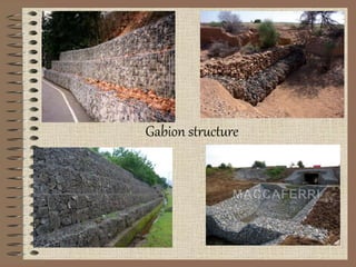
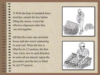
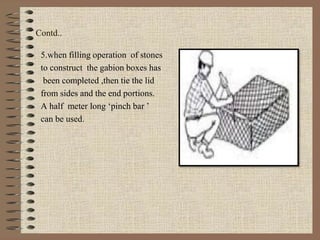
Welcome
welcome
welcome
Gabion structure
Gabion structure
Submitted by-sweta
M.TECH
OUT LINE
1.General Information About Gabion
2.Introduction
3.Characteristics
4.Uses Of Gabion
5.Gabion Structures Employment
6.Advantages Of Gabions
7.Construction Of Gabion Structure
8.Construction Steps
9.Computation Of Construction Cost Of Gabion.
10.Computation Procedure .
11.case study
12.reference
general information about gabion
OriginatedINITALY.
Basicallyrectangularwiremesh.
Filledwithstones.
Sizeofthestonesfilledisalwaysgreater
thanthemeshopening.
INTRODUCTION
Accordingtooxforddictionary :: Acylindricalbasketor
containerfilledwith earth,stones,orothermaterialandin
civilengineeringworks.
Isawiremeshcageorbasketfilledwithstones.
Agabionisabigwireboxfullofsmallstone.
.
CHARACTERSTICS:
FLEXIBLE
PERMIABLE
ECONOMIC $
BOXES ARE MADE OF GALVENISED WIRE.
USES OF GABION
GullyControl.
TorrentControl
LandslipControl,landSlideControl
RiverBankProtectionWorks
GABION STRUCTURES ARE EMPLOYED(Gupta&dalre 1967
As a retaining wall
Gabionstructureusedasretainingwalliscalledasgabionretaining
wall.
USES -
Unstable condition
Constructed to any height and shape.
 As a spur:
For controlling stream bank erosion.
Depth of spur’s foundation should be kept deeper towards upstream
side.
As a drop structure:
Gabion structure used as a drop structure are called as gabion drop
structure.
Reduces gully gradient. to serve as silt trip.
It is used where the drop height is more than 1 m.
5 cm thick concrete should be furnished after settlement
 As a flexible apron:
Gabion aprons are extensively used as flexible apron to act as a
revetment , retaining wall to protect the existing structure.
Gabion structure as revetment
Its main function is to provide the blanket type protection to
the affected surface.
Gabion structure for lining
The gabion also employed for lining the beds and banks of the
water cores
Maximum slope for the channel lining is1:1 or 1.5:1.
Advantages of gabions
1)Efficient
2)Permanent
3)Easy to construct
4)Economical
Special features which proves as advantages
1)It is flexible structure
2It is a permanent structure
3)It is a stable structure
4)It is a economical structure
Construction of gabion structure
Material required –
1.Galvanised wire
2.Hexagonal triple twisted mesh in the size ranging from 7.5to15cm
3.Wire no-8 gauge, less than10 gauge is not used
Construction steps
1)Assembled each gabion unit by
binding there vertical edges with
the help of about 12-15 cm long
wire ties. it is good to make 5 ties
per metre height.
2) As per plane place, few empty
unit on position and tie them with
the adjacent boxes, using at lest 5
wire per metre.
3) With the help of standard fence
stretcher, stretch the box before
filling the stones, to provide
effective alignment after they
are tied together.
4)Filled the rocks into stretched
boxes and also insert connecting
in each cell. When the box is
filled by its 1/3 portion, the first
four wires, two in each direction
in each cell are placed. repeat the
procedure until the box is filled
by its2/3rd portion
Contd..
5.when filling operation of stones
to construct the gabion boxes has
been completed ,then tie the lid
from sides and the end portions.
A half meter long ‘pinch bar ’
can be used.
Computation of construction cost of gabion
parameter considered:
1.size of gabion box(length, width and depth)
2.capacity of box (m³)
3.area of wire mesh in each gabion (m²)
4.density of wire used (kg/m³)
5.cost of mesh construction (Rs/kg)
6.labour charge per box including construction cost of wire mesh.
7.cost of rock filling (Rs/m³)
computation procedure :
step(1): find out the area of mesh involved in each gabion box.
Step(2) : calculate the weight of wire needed per box. it is given as
weight= density of wire x area of mesh in each box.
Step(3) : calculate cost per box. it is obtained as:
weigh of box x cost.
step(4) : estimate labour charge per box including construction cost
of wire mesh, which is computed as:
labour charge x area of wire mesh of one gabion box.
step(5) : compute the cost of rock filling per 100m³ .
It is given as cost of rock filing x capacity of gabion.
Step(6) : find the total cost of construction which is the sum of Step(3),
Step(4) , Step(5).
CASE STUDY : PERFORMANCE OF GULLY PLUG
STRUCTURE(GABION) IN BLACK CLAY SOIL.
D. H. RANADE, L. K. JAIN, S. K. VISHWAKARMA S.M
NARULKAR and A. S .TOMAR
AICRP On Dry land Agriculture, College of Agriculture , J .N. K.
V. V campus, Indore INDIA
Published in INDIAN JOURNAL OF SOIL CONSERVATION
Volume 29 -2001
INTRODUCTION
The study was carried out in the year 2000 to assess the cause
of failure in gully reclamation in the black soils of malwa
region of village pipliyatapha.
Gabions had been constructed in the lower reaches of river
gambhir under hingoia pipliyatapha watershed area during
the year 1991-92
The soils of experimental area are highly erodible(clay 55
percent).
The average annual rainfall of area is 958mm.
The total length of gully is found to be 216m in the year
2000(which was only 195m in the year1992).
MATERIALS AND METHODS
Two structures were constructed at vertical interval
of 2m i.e. at distance of 44m and 140m from gully
head.
It was observed that the gabion were constructed in
narrow sections of the gully in order to reduce cost
of construction.
It was also noticed that the height of the first
gabion was 1m but is increased to 2m in case of
second gabion.
Solar Wonders, ©2007 Florida Solar Energy Center
•
SI No. Design of the existing structure Dimensions(m)
Structure -1 Structure-2
A Hydrological design details
i) Length of crest 3.00 2.65
ii) Head over the crest 0.50 1.00
B) Hydraulic design details
i) Depth of cut-off wall 0.00 0.00
ii) Depth of head wall 1.00 2.00
iii) Length of head wall
extension(on one side)
1.00 1.00
Iv Depth of toe wall 0.00 0.00
V Length of apron 0.00 0.00
Vi Length of side wall 0.00 0.00
vii Length of wing wall 0.00 0.00
DETAILS OF EXISTING GULLY PLUG STRUCTURES
It was observed that when runoff water entered
from the wider section to narrow section(3.00 to
2.65m width)
Its velocity increased tremendously an and crossed
the erosive velocity limit.
Instead of reclaiming the gully, it increased in
gully width and depth.
In this case the gully bed deepening up to 16m
(0.4m) from second structure while it was limited
to 9.50m(.73m)in the first structure.
Results and discussion
even after structural failure, The head wall of
gabion remained at its location this indicates that
the gabion is very stable structure.
From the above study, it is observed that the
gabion structure should be constructed in a fairly
reasonable uniform section of gully instead of
narrow section.
SEDIMENT RETENTION BY GABION STRUCTURE IN
BUNGA WATERSHED
P.K. GOEL, J.S.SAMRA AND R.C. BANSAL
Central soil and water conservation research and training
institute, research centre, chandigarh.
Published in INDIAN JOURNAL OF SOIL
CONSERVATION Volume 24 -1996
INTRODUCTION
The cost of gabion construction is almost ½
to 2/3rd of the cement masonry( juyal et al.,1992).
 gabion structures have relatively long life (20-25
years) in comparison to cement masonry permanent
structure
STUDY AREA
 bunga-II watershed project area is located in bunga,
Ambala (Haryana) and situated at 30ᵒ 42’N latitude and 77ᵒ
10’ E longitude.
Average rainfall o area is 1100mm.
Eight crate wire stone check dams constructed in the
catchment of water harvesting dam of bunga-II watershed
project in ambala district of haryana were selected for the
assessment of their effectiveness in retaining sediment.
DESIGN DETAILS OF CRATE WIRE STONE CHECK DAM IN THE
CATCHMENT OF BUNG-II dam
Structure
Number
Capacity of the structure up
To crest level(cum)
Capacity lost in (cum) Percentag
e of
capacity
lost in two
years
At the time
Of(june199
1)
constructio
n
After one
year(1991)
After two
year(1992)
One year Two year
1 642.2 537.2 290.0 105.0 352.2 54.84
2 550.9 464.5 65.2 86.4 485.7 88.15
3 380.4 298.5 32.6 81.9 347.8 91.43
4 295.9 198.2 * 97.7 * *
5 207.5 200.3 164.3 7.2 43.2 20.81
6 1603.9 1132.2 837.0 471.7 766.9 47.81
7 543.3 425.3 315.2 118.0 228.1 41.98
8 134.6 112.2 43.7 22.4 85.9 63.81
Within a short span of two years, loss in retention capacity
of structures ranged from minimum 20.18 percent to
maximum 91.43pecent with average loss of 58.40 percent .
Out of eight structures under study, two(structure
number2&3)lost almost 90% of their capacity due to sediment
deposition
The detained sediment was found conducive supporting the
growth of vegetation which in tern further improved control of
erosion.
This indicate that the crate wire stone check dams are very
much effective in retaining the sediment which would have
found its way to reservoir resulting in loss of valuable storage
capacity.
REFERENCES
Text book of SOIL AND WATER CONSERVATION ENGINEERING by :
R. Suresh
Google images.
Ranade, D. H., Jain, L. K., Vishwakarma, S. K., Narulkar, S. M., Tomar, S.
M., 2001, performance of gully plug structure(gabion) in black clay soil
region-A case study. indian journal of soil conservation 29 (1):88-90
Goel, P. K., Samra, J. S., Bansal, R.C., 1996,sediment retention by gabion
structure in bunga watershed. indian journal of soil conservation 27
(2):107-110
Gabion s are used as :-
Gully control structure
As wellas decoration
purposes.
Thank you
Thank you
Thank you

Gabion structures ppt

  • 1.
  • 2.
  • 3.
  • 4.
    OUT LINE 1.General InformationAbout Gabion 2.Introduction 3.Characteristics 4.Uses Of Gabion 5.Gabion Structures Employment 6.Advantages Of Gabions 7.Construction Of Gabion Structure 8.Construction Steps 9.Computation Of Construction Cost Of Gabion. 10.Computation Procedure . 11.case study 12.reference
  • 5.
    general information aboutgabion OriginatedINITALY. Basicallyrectangularwiremesh. Filledwithstones. Sizeofthestonesfilledisalwaysgreater thanthemeshopening.
  • 6.
    INTRODUCTION Accordingtooxforddictionary :: Acylindricalbasketor containerfilledwithearth,stones,orothermaterialandin civilengineeringworks. Isawiremeshcageorbasketfilledwithstones. Agabionisabigwireboxfullofsmallstone. .
  • 7.
  • 8.
  • 9.
    GABION STRUCTURES AREEMPLOYED(Gupta&dalre 1967 As a retaining wall Gabionstructureusedasretainingwalliscalledasgabionretaining wall. USES - Unstable condition Constructed to any height and shape.
  • 10.
     As aspur: For controlling stream bank erosion. Depth of spur’s foundation should be kept deeper towards upstream side. As a drop structure: Gabion structure used as a drop structure are called as gabion drop structure. Reduces gully gradient. to serve as silt trip. It is used where the drop height is more than 1 m. 5 cm thick concrete should be furnished after settlement
  • 11.
     As aflexible apron: Gabion aprons are extensively used as flexible apron to act as a revetment , retaining wall to protect the existing structure.
  • 12.
    Gabion structure asrevetment Its main function is to provide the blanket type protection to the affected surface. Gabion structure for lining The gabion also employed for lining the beds and banks of the water cores Maximum slope for the channel lining is1:1 or 1.5:1.
  • 13.
    Advantages of gabions 1)Efficient 2)Permanent 3)Easyto construct 4)Economical Special features which proves as advantages 1)It is flexible structure 2It is a permanent structure 3)It is a stable structure 4)It is a economical structure
  • 14.
    Construction of gabionstructure Material required – 1.Galvanised wire 2.Hexagonal triple twisted mesh in the size ranging from 7.5to15cm 3.Wire no-8 gauge, less than10 gauge is not used
  • 15.
    Construction steps 1)Assembled eachgabion unit by binding there vertical edges with the help of about 12-15 cm long wire ties. it is good to make 5 ties per metre height. 2) As per plane place, few empty unit on position and tie them with the adjacent boxes, using at lest 5 wire per metre.
  • 16.
    3) With thehelp of standard fence stretcher, stretch the box before filling the stones, to provide effective alignment after they are tied together. 4)Filled the rocks into stretched boxes and also insert connecting in each cell. When the box is filled by its 1/3 portion, the first four wires, two in each direction in each cell are placed. repeat the procedure until the box is filled by its2/3rd portion
  • 17.
    Contd.. 5.when filling operationof stones to construct the gabion boxes has been completed ,then tie the lid from sides and the end portions. A half meter long ‘pinch bar ’ can be used.
  • 18.
    Computation of constructioncost of gabion parameter considered: 1.size of gabion box(length, width and depth) 2.capacity of box (m³) 3.area of wire mesh in each gabion (m²) 4.density of wire used (kg/m³) 5.cost of mesh construction (Rs/kg) 6.labour charge per box including construction cost of wire mesh. 7.cost of rock filling (Rs/m³)
  • 19.
    computation procedure : step(1):find out the area of mesh involved in each gabion box. Step(2) : calculate the weight of wire needed per box. it is given as weight= density of wire x area of mesh in each box. Step(3) : calculate cost per box. it is obtained as: weigh of box x cost. step(4) : estimate labour charge per box including construction cost of wire mesh, which is computed as: labour charge x area of wire mesh of one gabion box. step(5) : compute the cost of rock filling per 100m³ . It is given as cost of rock filing x capacity of gabion. Step(6) : find the total cost of construction which is the sum of Step(3), Step(4) , Step(5).
  • 20.
    CASE STUDY :PERFORMANCE OF GULLY PLUG STRUCTURE(GABION) IN BLACK CLAY SOIL. D. H. RANADE, L. K. JAIN, S. K. VISHWAKARMA S.M NARULKAR and A. S .TOMAR AICRP On Dry land Agriculture, College of Agriculture , J .N. K. V. V campus, Indore INDIA Published in INDIAN JOURNAL OF SOIL CONSERVATION Volume 29 -2001
  • 21.
    INTRODUCTION The study wascarried out in the year 2000 to assess the cause of failure in gully reclamation in the black soils of malwa region of village pipliyatapha. Gabions had been constructed in the lower reaches of river gambhir under hingoia pipliyatapha watershed area during the year 1991-92 The soils of experimental area are highly erodible(clay 55 percent). The average annual rainfall of area is 958mm. The total length of gully is found to be 216m in the year 2000(which was only 195m in the year1992).
  • 22.
    MATERIALS AND METHODS Twostructures were constructed at vertical interval of 2m i.e. at distance of 44m and 140m from gully head. It was observed that the gabion were constructed in narrow sections of the gully in order to reduce cost of construction. It was also noticed that the height of the first gabion was 1m but is increased to 2m in case of second gabion.
  • 23.
    Solar Wonders, ©2007Florida Solar Energy Center • SI No. Design of the existing structure Dimensions(m) Structure -1 Structure-2 A Hydrological design details i) Length of crest 3.00 2.65 ii) Head over the crest 0.50 1.00 B) Hydraulic design details i) Depth of cut-off wall 0.00 0.00 ii) Depth of head wall 1.00 2.00 iii) Length of head wall extension(on one side) 1.00 1.00 Iv Depth of toe wall 0.00 0.00 V Length of apron 0.00 0.00 Vi Length of side wall 0.00 0.00 vii Length of wing wall 0.00 0.00
  • 24.
    DETAILS OF EXISTINGGULLY PLUG STRUCTURES
  • 25.
    It was observedthat when runoff water entered from the wider section to narrow section(3.00 to 2.65m width) Its velocity increased tremendously an and crossed the erosive velocity limit. Instead of reclaiming the gully, it increased in gully width and depth. In this case the gully bed deepening up to 16m (0.4m) from second structure while it was limited to 9.50m(.73m)in the first structure.
  • 26.
    Results and discussion evenafter structural failure, The head wall of gabion remained at its location this indicates that the gabion is very stable structure. From the above study, it is observed that the gabion structure should be constructed in a fairly reasonable uniform section of gully instead of narrow section.
  • 27.
    SEDIMENT RETENTION BYGABION STRUCTURE IN BUNGA WATERSHED P.K. GOEL, J.S.SAMRA AND R.C. BANSAL Central soil and water conservation research and training institute, research centre, chandigarh. Published in INDIAN JOURNAL OF SOIL CONSERVATION Volume 24 -1996
  • 28.
    INTRODUCTION The cost ofgabion construction is almost ½ to 2/3rd of the cement masonry( juyal et al.,1992).  gabion structures have relatively long life (20-25 years) in comparison to cement masonry permanent structure
  • 29.
    STUDY AREA  bunga-IIwatershed project area is located in bunga, Ambala (Haryana) and situated at 30ᵒ 42’N latitude and 77ᵒ 10’ E longitude. Average rainfall o area is 1100mm. Eight crate wire stone check dams constructed in the catchment of water harvesting dam of bunga-II watershed project in ambala district of haryana were selected for the assessment of their effectiveness in retaining sediment.
  • 30.
    DESIGN DETAILS OFCRATE WIRE STONE CHECK DAM IN THE CATCHMENT OF BUNG-II dam Structure Number Capacity of the structure up To crest level(cum) Capacity lost in (cum) Percentag e of capacity lost in two years At the time Of(june199 1) constructio n After one year(1991) After two year(1992) One year Two year 1 642.2 537.2 290.0 105.0 352.2 54.84 2 550.9 464.5 65.2 86.4 485.7 88.15 3 380.4 298.5 32.6 81.9 347.8 91.43 4 295.9 198.2 * 97.7 * * 5 207.5 200.3 164.3 7.2 43.2 20.81 6 1603.9 1132.2 837.0 471.7 766.9 47.81 7 543.3 425.3 315.2 118.0 228.1 41.98 8 134.6 112.2 43.7 22.4 85.9 63.81
  • 31.
    Within a shortspan of two years, loss in retention capacity of structures ranged from minimum 20.18 percent to maximum 91.43pecent with average loss of 58.40 percent . Out of eight structures under study, two(structure number2&3)lost almost 90% of their capacity due to sediment deposition The detained sediment was found conducive supporting the growth of vegetation which in tern further improved control of erosion. This indicate that the crate wire stone check dams are very much effective in retaining the sediment which would have found its way to reservoir resulting in loss of valuable storage capacity.
  • 32.
    REFERENCES Text book ofSOIL AND WATER CONSERVATION ENGINEERING by : R. Suresh Google images. Ranade, D. H., Jain, L. K., Vishwakarma, S. K., Narulkar, S. M., Tomar, S. M., 2001, performance of gully plug structure(gabion) in black clay soil region-A case study. indian journal of soil conservation 29 (1):88-90 Goel, P. K., Samra, J. S., Bansal, R.C., 1996,sediment retention by gabion structure in bunga watershed. indian journal of soil conservation 27 (2):107-110
  • 33.
    Gabion s areused as :- Gully control structure As wellas decoration purposes.
  • 34.