1. The document discusses electrical submersible pumps (ESPs), which are pumps used to lift fluid out of wells. An ESP has a hermetically sealed motor attached directly to the pump body, allowing the entire assembly to be submerged.
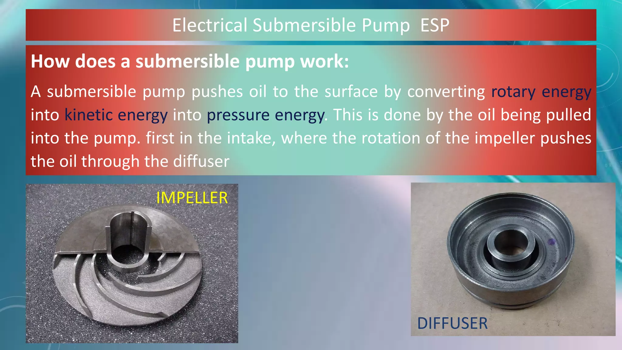
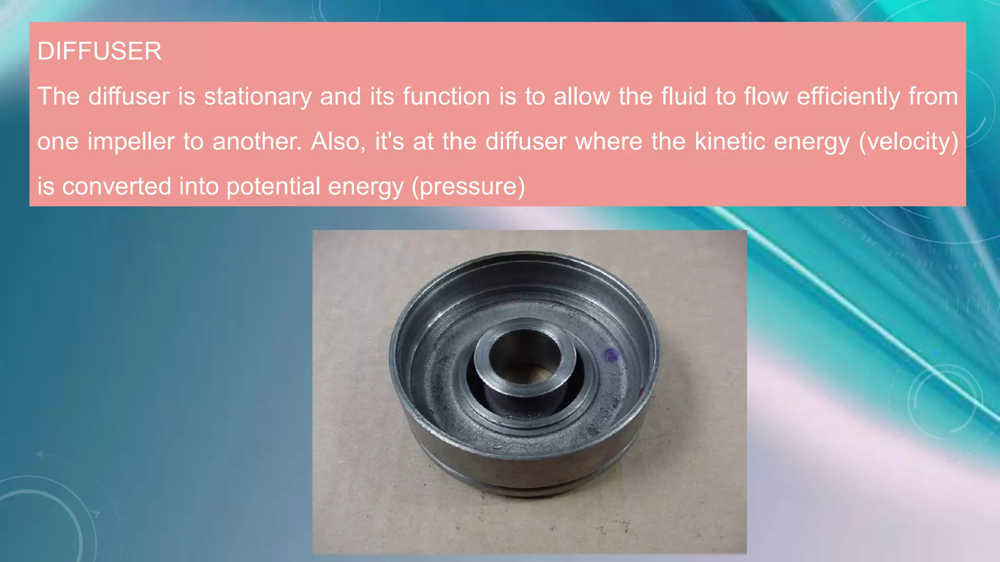
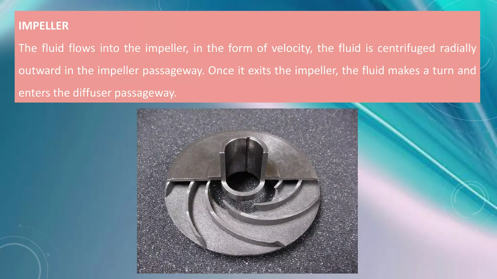
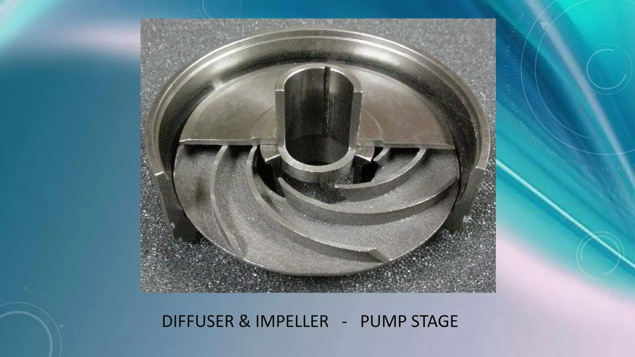
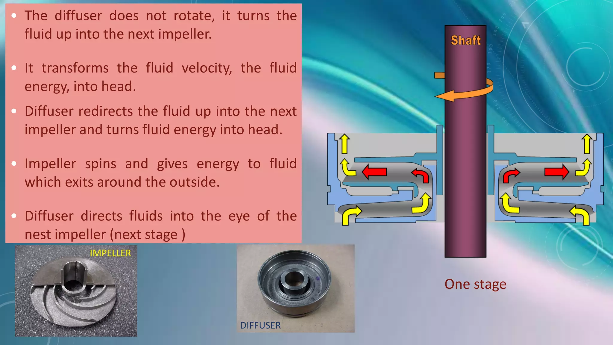
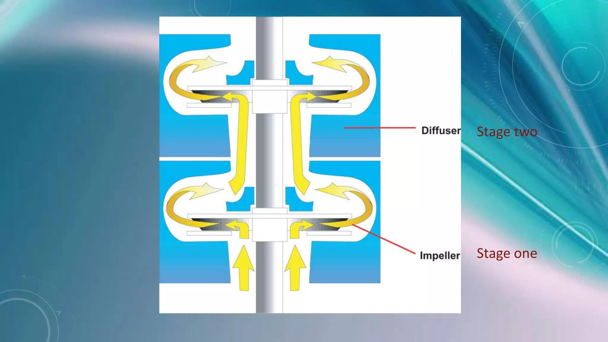
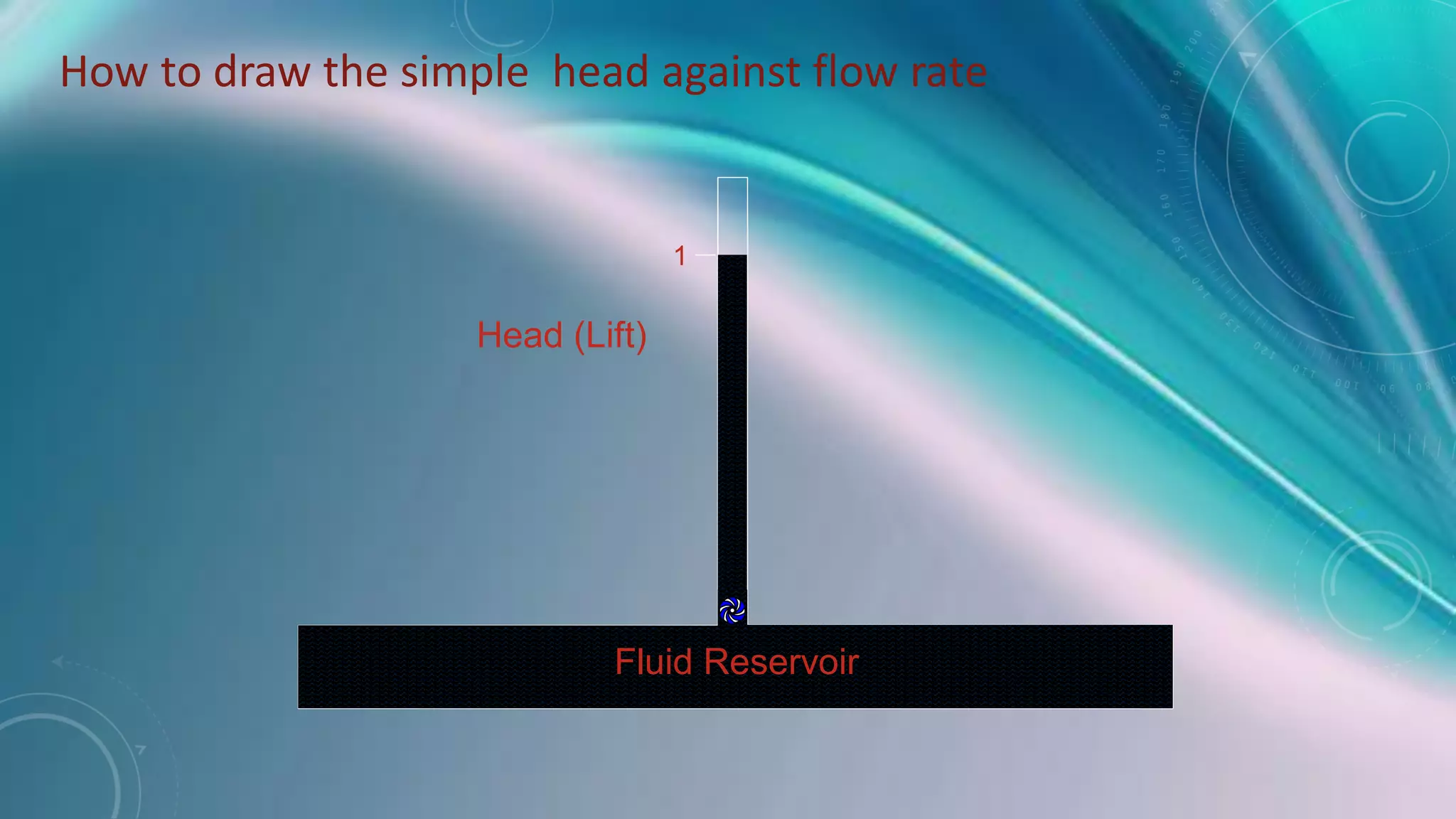
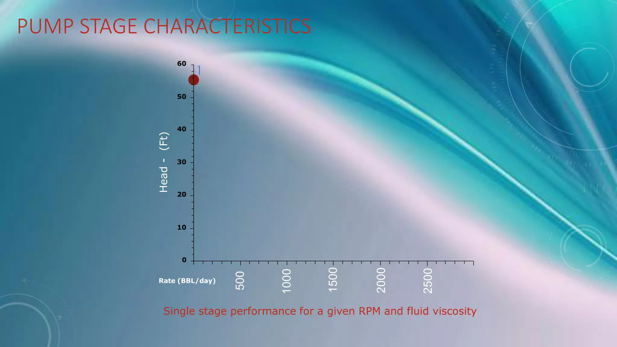
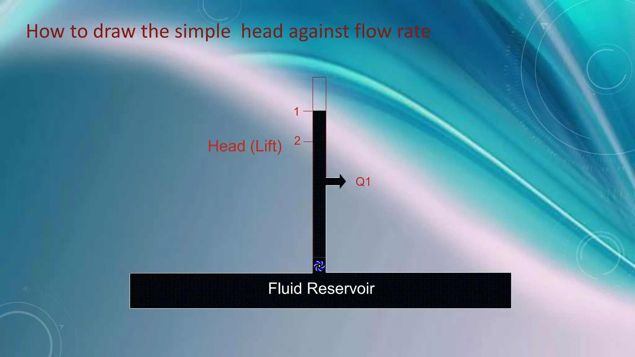
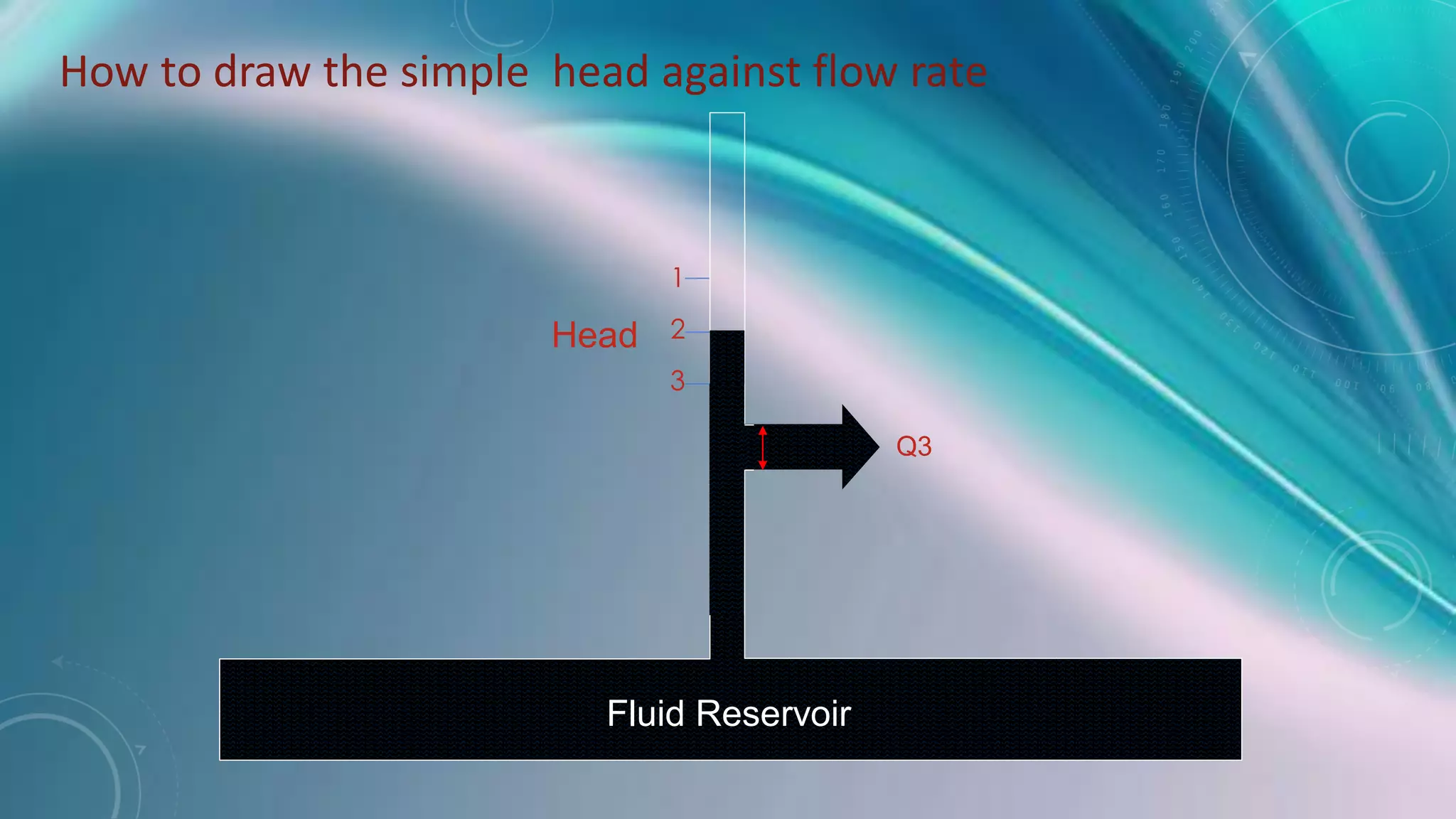
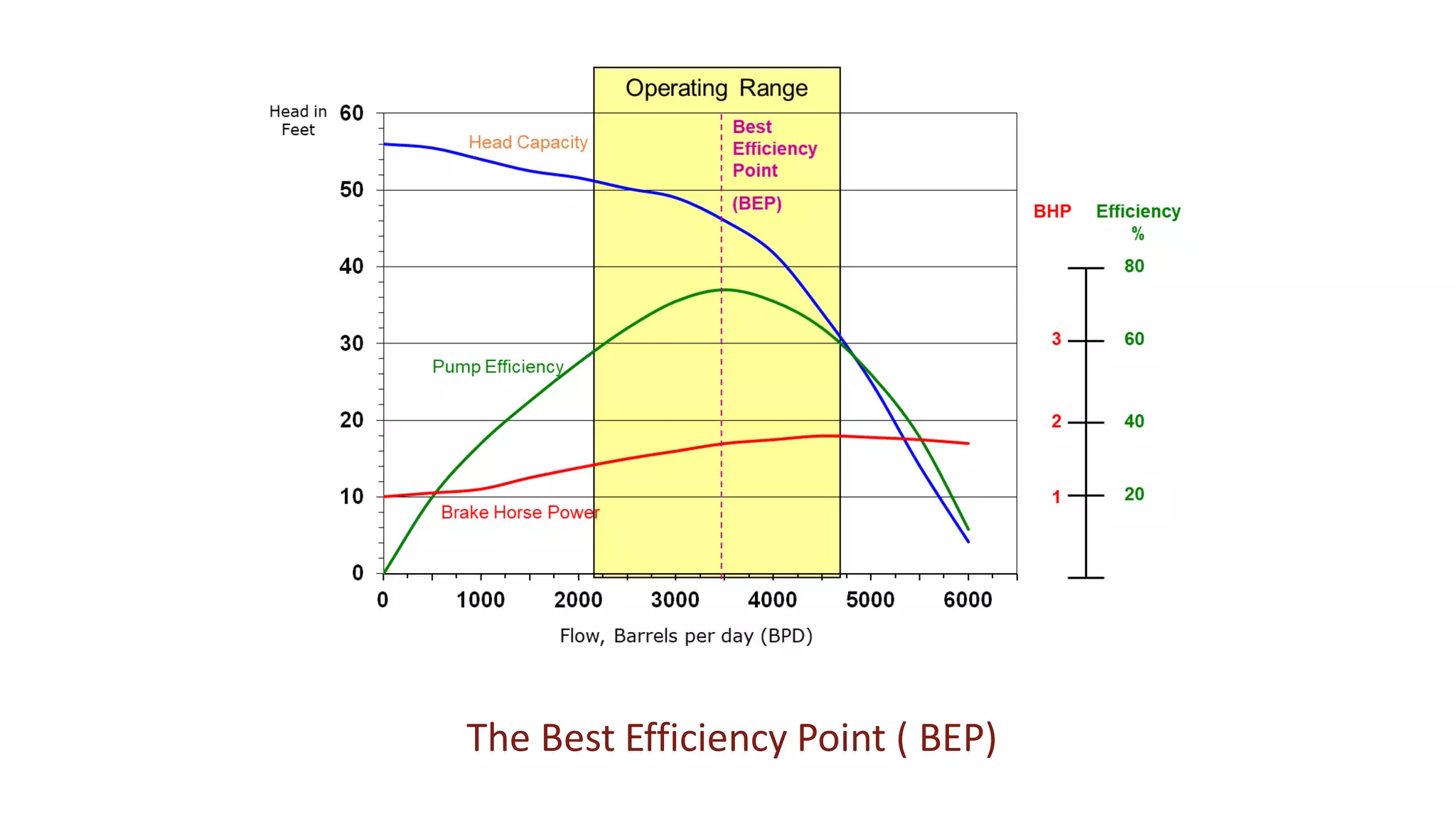
2. ESPs work by using an impeller and diffuser to convert the rotational energy of the motor into kinetic and pressure energy in the fluid. The impeller spins and adds energy to the fluid, while the stationary diffuser converts this energy into fluid pressure.
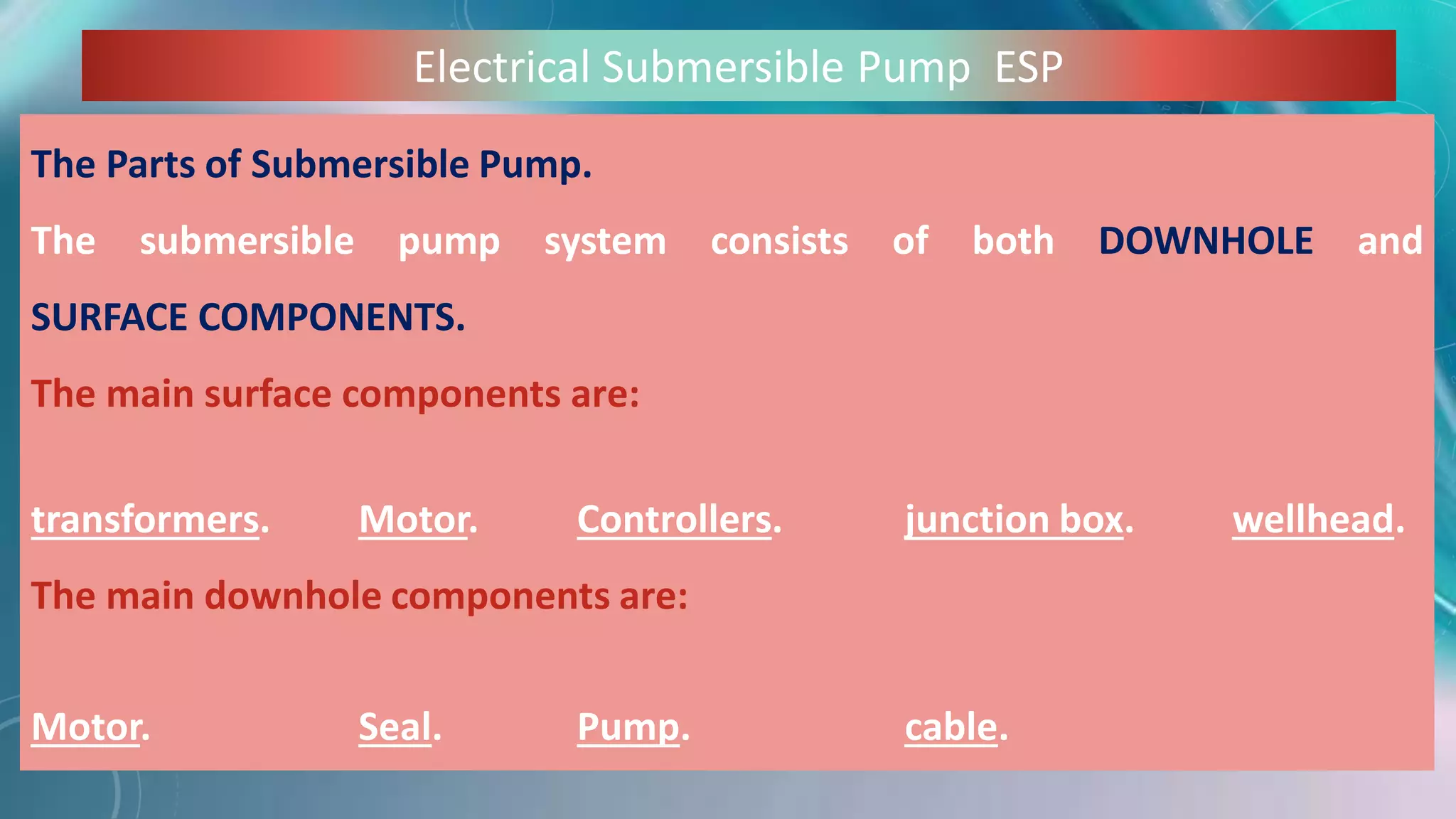
3. The main components of an ESP system are the downhole components of the motor, seal, pump and cable, as well as the surface components of transformers, motor controllers, and a junction box