Download to read offline


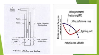
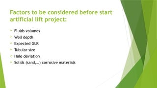
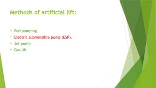
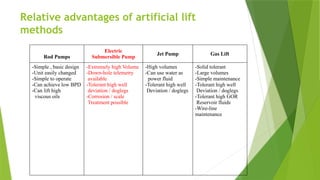
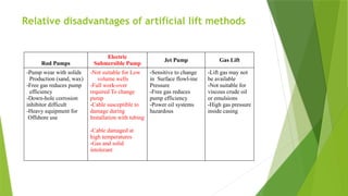
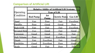
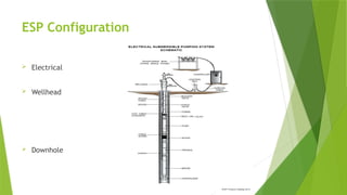
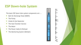
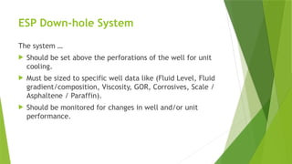


The document provides an overview of electric submersible pumps (ESPs), including definitions and calculations related to productivity index and inflow/outflow performance relationships. It discusses artificial lift systems and their components, emphasizing various methods and their advantages and disadvantages for oil production. Additionally, it details the configuration, operation, and maintenance of ESP systems, including downhole components and surface equipment necessary for effective pump operation.


