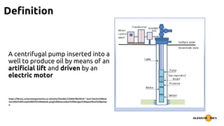
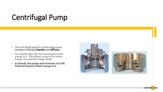
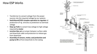
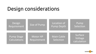
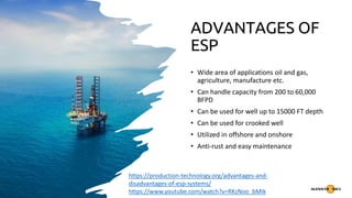
2. Outline
Introduction
•Definition of ESP
•Importance of ESP in oil and gas industry
•Brief History of ESP
ESP Component
•Motor
•Seal Section
•Intake
•Power cable
•Pump
How ESP Works
ESP Design Considerations
ESP Applications
Advantages of ESPs
Limitation and Challenges
4. Definition
A centrifugal pump inserted into a
well to produce oil by means of an
artificial lift and driven by an
electric motor
https://library.universitaspertamina.ac.id/xmlui/handle/123456789/431#:~:text=Electic%20Sub
mersible%20Pump%20(ESP)%20adalah,yang%20disesuaikan%20dengan%20spesifikasi%20pomp
a.
5. Importance of ESP in Oil and Gas
Industry
• ESPs is necessarily used for regulating production of oil and
gas – available in range sizes and capacities
• Best known as an effective artificial lift method of pumping
production fluids to the surface
• Considered as low maintenance and cost effective
6. ESP History
In 1911, 18-year-old Russian engineer
Armais Arutunoff (June 21, 1893 -
February 1978) invented the first
electric motor that operated in water.
He added a drill and a centrifugal pump
to the motor, inventing what is now
known as the electric submersible pump.
Arutunoff immigrated to the US, where
he founded Russian Electrical Dynamo of
Arutunoff, or REDA. Electric submersible
pumps are now operating in onshore
and offshore fields throughout the
world.
8. ESP Component
Downhole
• Motor
• Seal Section / Protector
• Pump
• Power Cable
• Intake
Surface
• Control Panel / VSD
• Transformer
• Junction box
• Power Cable
9. Motor
• Typically a-three phase
Induction motor that is located
in the bottom of the wellbore
and is connected to the pump by
shaft
• Nominal Speeds 3450 rpm / 60
Hz or 2916 rpm /50 Hz
• Filled with light oil that required
for lubrication and cooling
• During Operation oil in the
motor heats up and expands, the
excess oil travels from the
motor up and in to seal section
10. Motor Diagram : Stator
https://production-technology.org/esp-motor/
The Stator The stator is the core or
electrical field of the motor. It is
composed of the housing material for
the desired diameter, the stator core,
and the stator windings
The housing material forms the
cover for the motor and is threaded at
both ends for head and base
components. The housing can be of
different diameters and its material
can be chosen for different
applications, depending upon the
environment
The stator core is composed of
laminations stacked under pressure to
insure a permanently tight core.
Laminations are thin sheets of die-
punched steel or bronze material
11. Motor Diagram : Stator
https://production-technology.org/esp-motor/
The stator windings are made from either
Polyimide or PEEK material, for primary
magnetizing winding wound through the die-
punched slots in the stator core
12. Motor Diagram : Rotor
https://production-technology.org/esp-motor/
The rotor is a device that rotates
inside of the stator core. The rotor is
made up of rotor laminations that are
smaller in diameter from the stator
laminations and these create the iron
core. Inside each slot are copper bars
with supporting copper end rings.
Because the structure resembles the
cage used to exercise squirrels, rotors
of this type are called “Squirrel-Cage
rotors”.
13. Motor Diagram : Thrust Bearing
https://production-technology.org/esp-motor/
The motor thrust bearing is installed
at the top of the rotor string. It is
designed to hold the weight of the
entire rotor string. There are several
types of motor thrust bearings. The
thrust bearing limits will indicate the
type of load required for the selected
bearing material
14. Motor Diagram : Pothead
https://production-technology.org/esp-motor/
The pothead is a key part to connect
the motor with the power cable; its
mechanical and end sealing ensure
the long-term operation of the motor.
15. Protector / Seal Section
Connected above the motor
Motor Shaft and seal shaft connected via coupler
Acts as Oil Reservoir for motor
Contain a thrust modul that absorbs thrust generated by the shafts of the gas
separator and pump
17. Power Cable
• Begins at the transformer
• Passes through the surface
controller, Junction box and
wellhead
• Attached to the production
tubing and run the entire
length of the well into motor
18. Pump intake / Gas Separator
• Connected between protector and pump section
• Provides suction to the pump
• Two types :
• Straight pump intake : provides suction to the pump with out separating gas
• Gas Separator intake : separate gas and allow only liquid to the pump station
• Types in Gas Separator : Poor Boy or Reverse flow separator
• routes well fluid 180 degrees downwards so that gas escapes upward in to annulus and only
liquid enters through pull tube
• Rotary gas separator works on centrifugal action.Keeps the heavier fluid(liquid)to the
periphery where as lighter fluid(gas)flows through the center in to annulus via a flow
devoured
19. Centrifugal Pump
• The centrifugal pump is a multi-stage pump,
Consists of stacked impeller and diffuser
• the impeller takes the fluid and imparts kinetic
energy to it. The diffuser converts this kinetic
energy into potential energy (head)
• In Overall, the pumps main function is to lift
fluid and imparts kinetic energy to it
21. • Transformer to convert voltage from the power
sources into the required voltage by our systems
• Switchboard/VSD complex operation to regulate oil
production of rig and also as protection to overload
voltage
• Step-up Trafo to convert low voltage to high voltage
required by motor
• Junction Box act as Jumper between surface cable
and downhole cable and protection to release gas
from downhole
• Assembly of sensors, motor, seal protection and
pump to lift oil from downhole to the tubing
How ESP Works
24. ESP Applications
Submersible pumps are used in these industries: drainage,
slurry pumping, sewage pumping, water wells, oil wells,
seawater handling, sewage treatment, fire fighting, deep well
drilling, irrigation, mine dewatering, artificial lifts and offshore
drilling rigs
25. ADVANTAGES OF
ESP
• Wide area of applications oil and gas,
agriculture, manufacture etc.
• Can handle capacity from 200 to 60,000
BFPD
• Can be used for well up to 15000 FT depth
• Can be used for crooked well
• Utilized in offshore and onshore
• Anti-rust and easy maintenance
https://production-technology.org/advantages-and-
disadvantages-of-esp-systems/
https://www.youtube.com/watch?v=RKzNoo_bMIk
26. Limitations and challenges
• One of the limitations of achieving full potential in pumped
wells is the presence of excessive free gas at pump intake.
Presence of free gas at pump intake affects the pump
performance negatively, reducing the liquid rates and the
pressure added by the pump
• Higher power needed for higher HP requirement