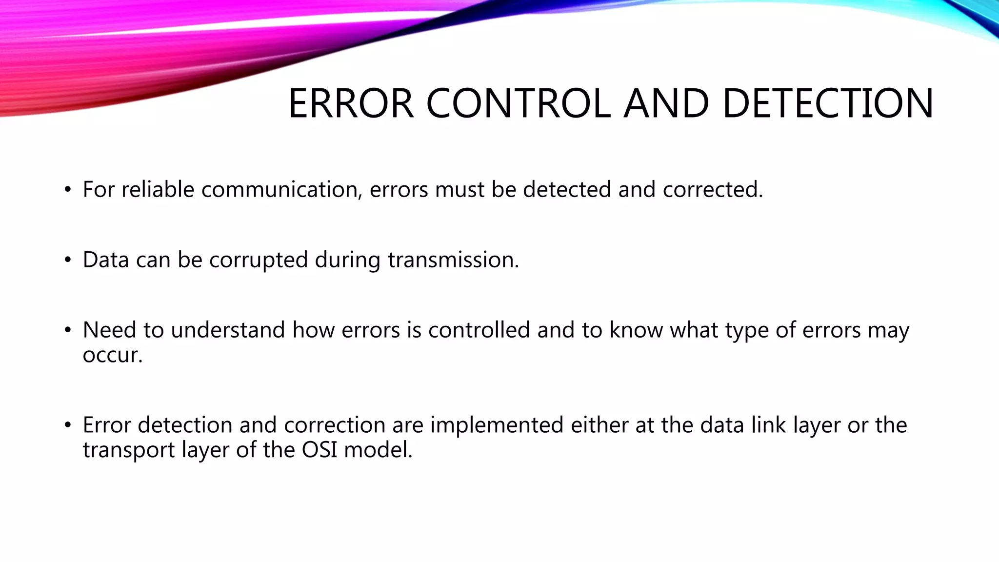
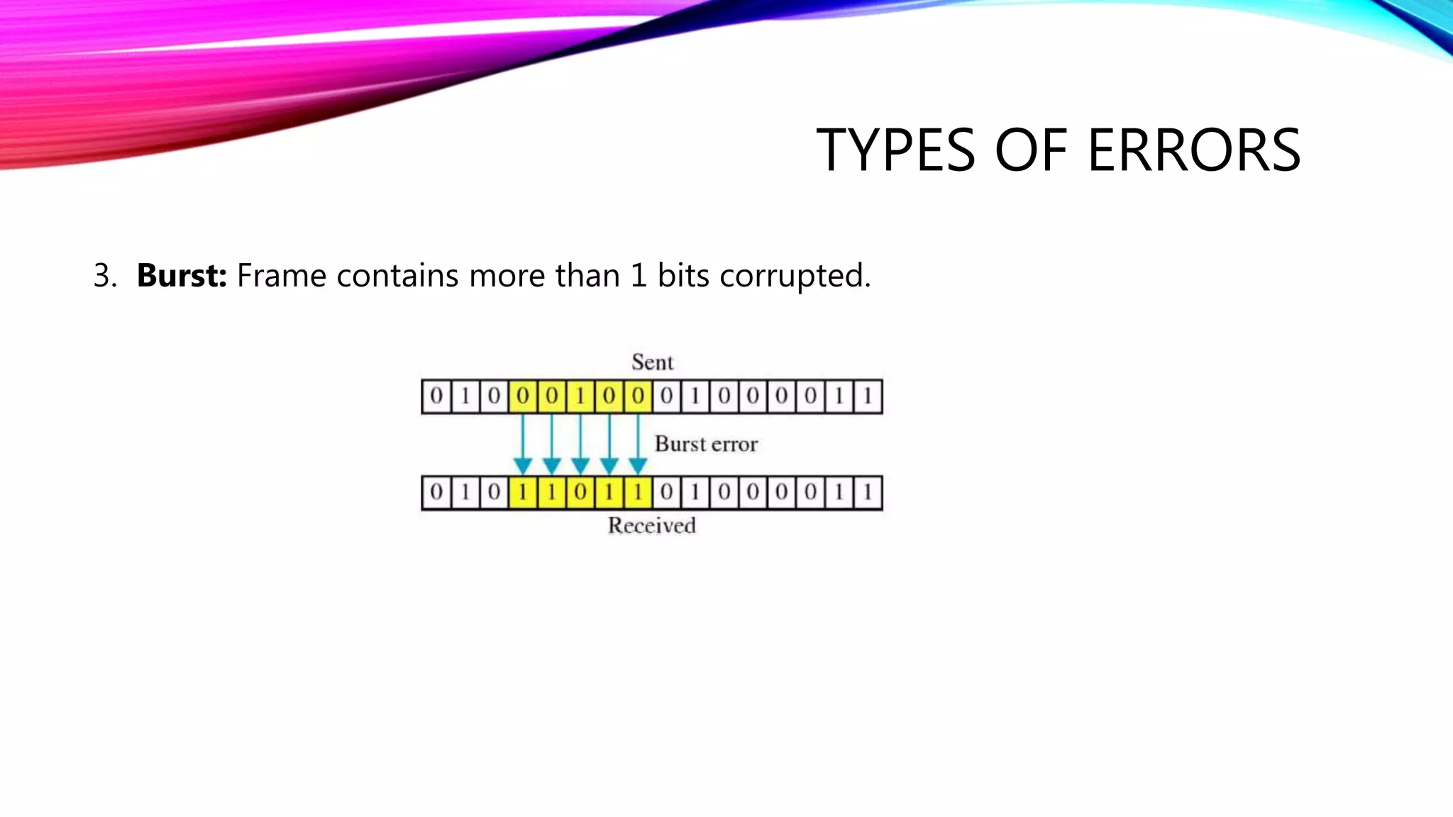
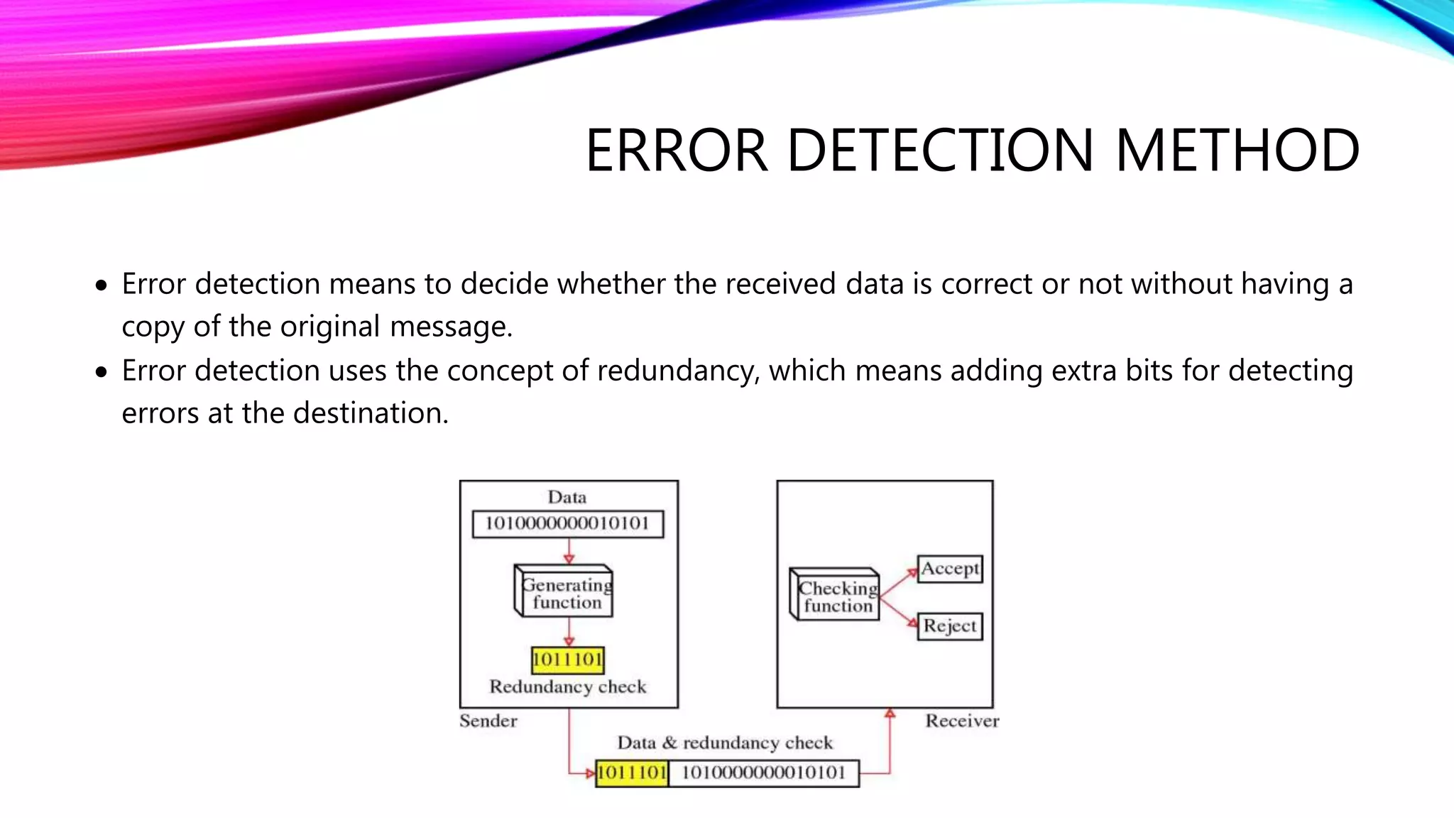
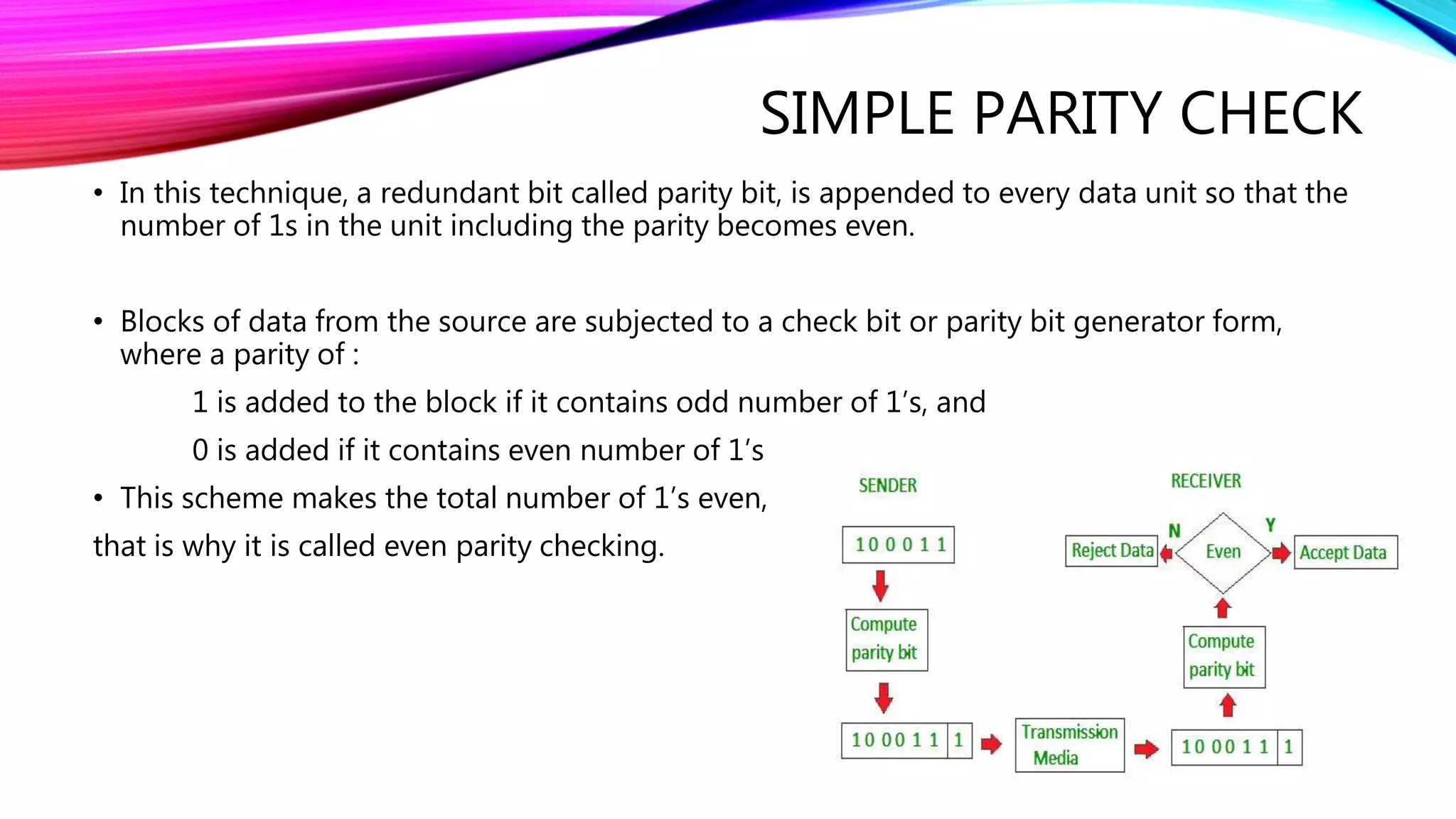
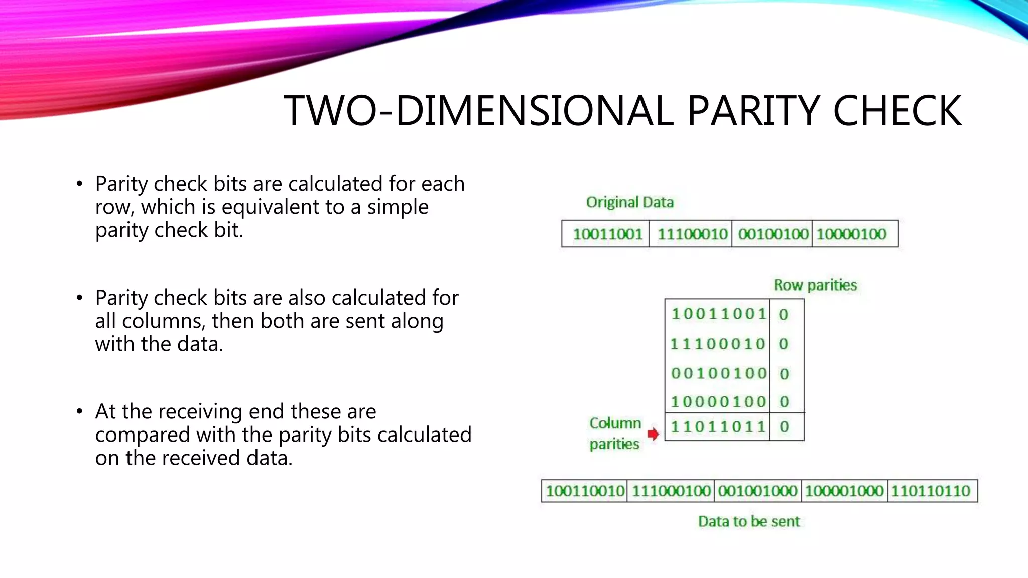
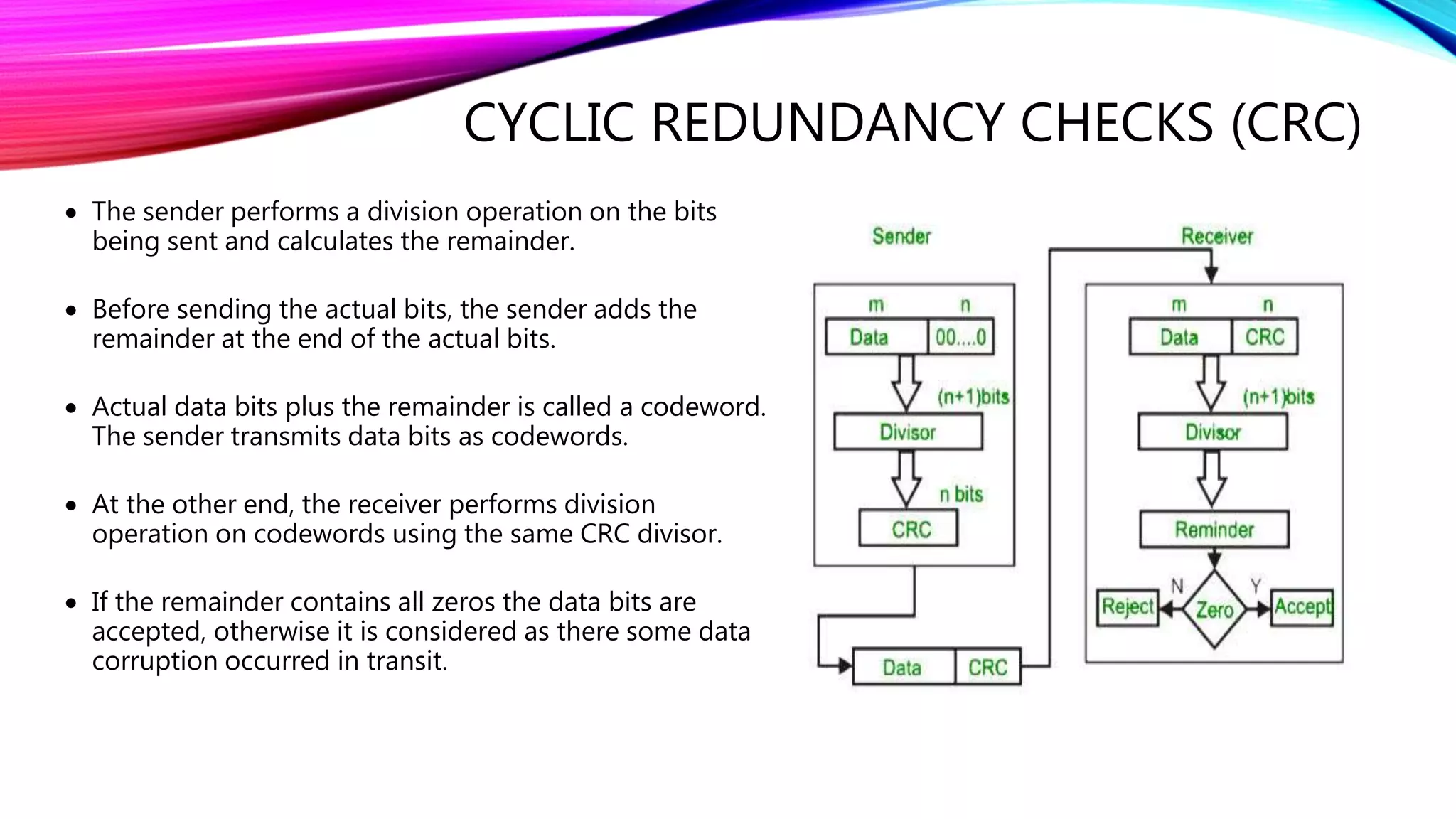
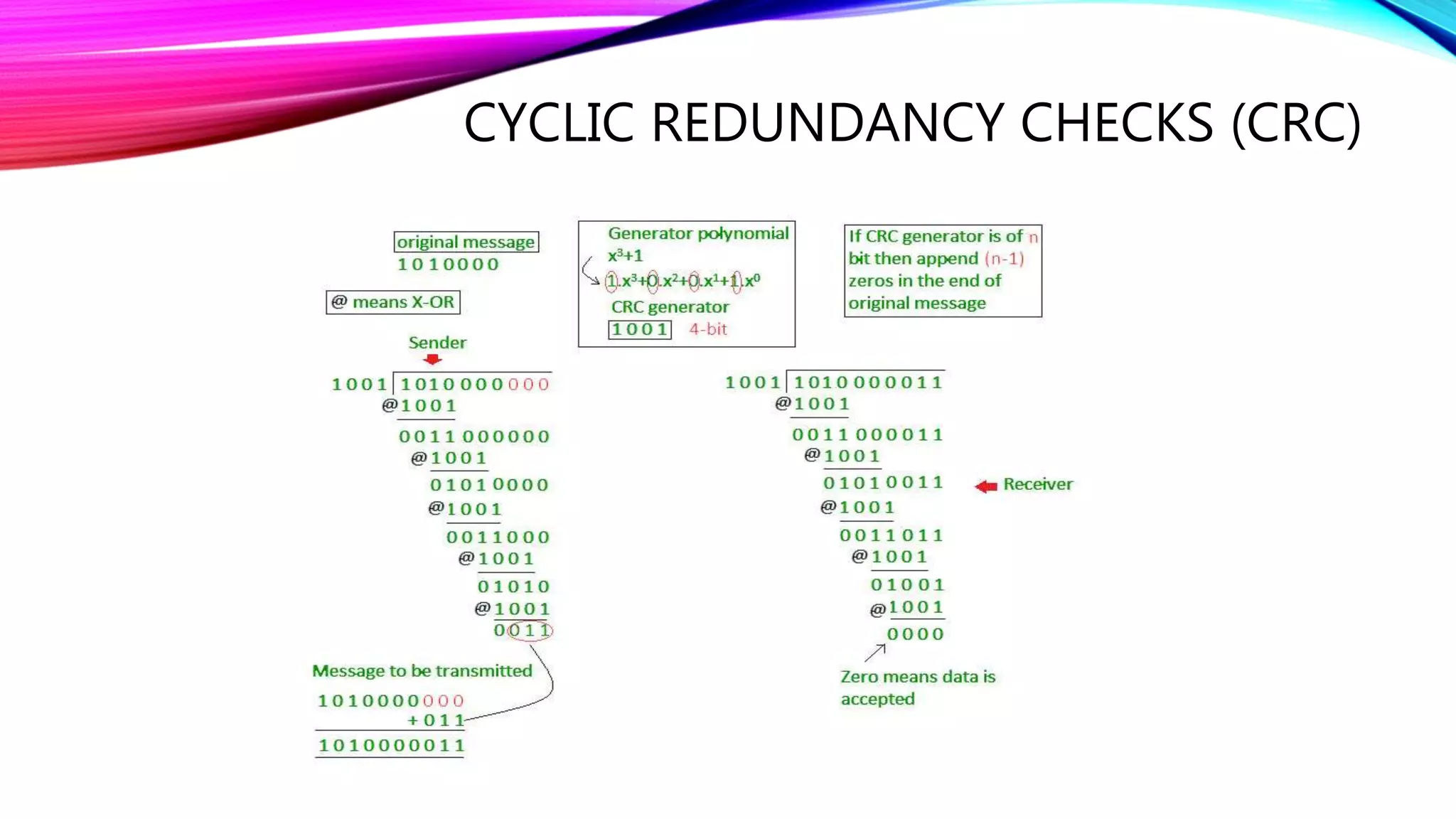
MCWC
ERROR DETECTION
TECHNIQUES
Kunjan Shah
170 410 107 103
LY CE 2
Batch c
ERROR CONTROL AND DETECTION
• For reliable communication, errors must be detected and corrected.
• Data can be corrupted during transmission.
• Need to understand how errors is controlled and to know what type of errors may
occur.
• Error detection and correction are implemented either at the data link layer or the
transport layer of the OSI model.
TYPES OF ERRORS
1. Single bit: In a frame is only one bit, anywhere though which is corrupt.
2. Multiple bit: Frame is received with more than one bits in corrupted state.
TYPES OF ERRORS
3. Burst: Frame contains more than 1 bits corrupted.
ERROR DETECTION METHOD
 Error detection means to decide whether the received data is correct or not without having a
copy of the original message.
 Error detection uses the concept of redundancy, which means adding extra bits for detecting
errors at the destination.
SIMPLE PARITY CHECK
• In this technique, a redundant bit called parity bit, is appended to every data unit so that the
number of 1s in the unit including the parity becomes even.
• Blocks of data from the source are subjected to a check bit or parity bit generator form,
where a parity of :
1 is added to the block if it contains odd number of 1’s, and
0 is added if it contains even number of 1’s
• This scheme makes the total number of 1’s even,
that is why it is called even parity checking.
TWO-DIMENSIONAL PARITY CHECK
• Parity check bits are calculated for each
row, which is equivalent to a simple
parity check bit.
• Parity check bits are also calculated for
all columns, then both are sent along
with the data.
• At the receiving end these are
compared with the parity bits calculated
on the received data.
CHECKSUM
 Here, the data is divided into k segments each
of m bits.
 In the sender’s end the segments are added
using 1’s complement arithmetic to get the
sum.
 The sum is complemented to get the
checksum.
 The checksum segment is sent along with the
data segments.
CHECKSUM
• At the receiver’s end, all received segments are added using 1’s complement arithmetic to
get the sum. The sum is complemented.
• If the result is zero, the received data is accepted; otherwise discarded.
Performance
 The checksum detects all errors involving an odd number of bits.
 It also detects most errors involving even number of bits.
CYCLIC REDUNDANCY CHECKS (CRC)
 CRC is the most powerful and easy to implement technique.
 CRC is based on binary division.
 The divisor is generated using polynomials.
 It is commonly used to detect accidental changes to data transmitted via
telecommunications networks and storage devices.
CYCLIC REDUNDANCY CHECKS (CRC)
 The sender performs a division operation on the bits
being sent and calculates the remainder.
 Before sending the actual bits, the sender adds the
remainder at the end of the actual bits.
 Actual data bits plus the remainder is called a codeword.
The sender transmits data bits as codewords.
 At the other end, the receiver performs division
operation on codewords using the same CRC divisor.
 If the remainder contains all zeros the data bits are
accepted, otherwise it is considered as there some data
corruption occurred in transit.
CYCLIC REDUNDANCY CHECKS (CRC)
Error detection techniques

Error detection techniques

  • 1.
  • 2.
    ERROR CONTROL ANDDETECTION • For reliable communication, errors must be detected and corrected. • Data can be corrupted during transmission. • Need to understand how errors is controlled and to know what type of errors may occur. • Error detection and correction are implemented either at the data link layer or the transport layer of the OSI model.
  • 3.
    TYPES OF ERRORS 1.Single bit: In a frame is only one bit, anywhere though which is corrupt. 2. Multiple bit: Frame is received with more than one bits in corrupted state.
  • 4.
    TYPES OF ERRORS 3.Burst: Frame contains more than 1 bits corrupted.
  • 5.
    ERROR DETECTION METHOD Error detection means to decide whether the received data is correct or not without having a copy of the original message.  Error detection uses the concept of redundancy, which means adding extra bits for detecting errors at the destination.
  • 6.
    SIMPLE PARITY CHECK •In this technique, a redundant bit called parity bit, is appended to every data unit so that the number of 1s in the unit including the parity becomes even. • Blocks of data from the source are subjected to a check bit or parity bit generator form, where a parity of : 1 is added to the block if it contains odd number of 1’s, and 0 is added if it contains even number of 1’s • This scheme makes the total number of 1’s even, that is why it is called even parity checking.
  • 7.
    TWO-DIMENSIONAL PARITY CHECK •Parity check bits are calculated for each row, which is equivalent to a simple parity check bit. • Parity check bits are also calculated for all columns, then both are sent along with the data. • At the receiving end these are compared with the parity bits calculated on the received data.
  • 8.
    CHECKSUM  Here, thedata is divided into k segments each of m bits.  In the sender’s end the segments are added using 1’s complement arithmetic to get the sum.  The sum is complemented to get the checksum.  The checksum segment is sent along with the data segments.
  • 9.
    CHECKSUM • At thereceiver’s end, all received segments are added using 1’s complement arithmetic to get the sum. The sum is complemented. • If the result is zero, the received data is accepted; otherwise discarded. Performance  The checksum detects all errors involving an odd number of bits.  It also detects most errors involving even number of bits.
  • 10.
    CYCLIC REDUNDANCY CHECKS(CRC)  CRC is the most powerful and easy to implement technique.  CRC is based on binary division.  The divisor is generated using polynomials.  It is commonly used to detect accidental changes to data transmitted via telecommunications networks and storage devices.
  • 11.
    CYCLIC REDUNDANCY CHECKS(CRC)  The sender performs a division operation on the bits being sent and calculates the remainder.  Before sending the actual bits, the sender adds the remainder at the end of the actual bits.  Actual data bits plus the remainder is called a codeword. The sender transmits data bits as codewords.  At the other end, the receiver performs division operation on codewords using the same CRC divisor.  If the remainder contains all zeros the data bits are accepted, otherwise it is considered as there some data corruption occurred in transit.
  • 12.