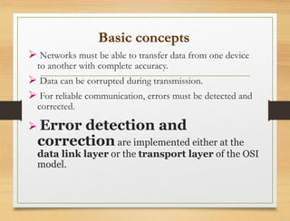
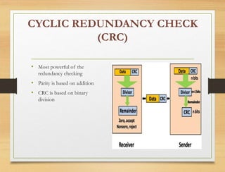
Linear Block and Cyclic Codes used
for two error detection and single
error correction
--------------------------------
Anwar liwaa shakir
MSC.
Communication engineer
Uok
Basic concepts
 Networks must be able to transfer data from one device
to another with complete accuracy.
 Data can be corrupted during transmission.
 For reliable communication, errors must be detected and
corrected.
 Error detection and
correction are implemented either at the
data link layer or the transport layer of the OSI
model.
Types of Errors
Error detection
-Check if any error has occurred
-Don't care the number of errors
-Don't care the positions of errors
 Error correction
-Need to know the number of errors
-Need to know the positions of errors
-More difficult
Single-bit error
Multiple -bit error
Single bit errors are the least likely type of errors in serial
data transmission because the noise must have a very short
duration which is very rare. However this kind of errors
can happen in parallel transmission.
Example:
If data is sent at 1Mbps then each bit lasts only
1/1,000,000 sec. or 1 μs.
For a single-bit error to occur, the noise must have a
duration of only 1 μs, which is very rare.
Burst error
The term burst error means that two or more bits in the
data unit have changed from 1 to 0 or from 0 to 1.
Burst errors does not necessarily mean that the errors
occur in consecutive bits, the length of the burst is
measured from the first corrupted bit to the last corrupted
bit. Some bits in between may not have been corrupted.
 Burst error is most likely to happen in serial
transmission since the duration of noise is normally
longer than the duration of a bit.
 The number of bits affected depends on the data rate and
duration of noise.
Example:
If data is sent at rate = 1Kbps then a noise of
1/100 sec can affect 10 bits.(1/100*1000)
If same data is sent at rate = 1Mbps then a noise
of 1/100 sec can affect 10,000 bits.(1/100*106)
Error detection
 Error detection means to decide whether the received
data is correct or not
 Error detection uses the concept of redundancy,
Redundancy
Parity check Linear block
The simplest method available –
it’s a linear ,systematic block code
 Single parity check
 Two dimensional parity check
How to use parity methods?
Parity generate-sender’s side
Parity detect-receiver’s side
TWO-DIMENTIONAL PARITY CHECK
(LRC)
 In two- dimensional parity check, a block of bits is divided into
rows and redundant row of bits is added to the whole block.
 Even parity concept
Example:
 In transmitter :
compute(m+n+1) parity bits
Drawbacks of 2D parity check
Figure : Two-dimensional parity-check code
• 1 affect 3 ,2 affect 3,3 affect 4 ,4 affect 4 –so can not detect in this case
• Disadvantage :too many check bits!!
• Can not detect error, if bits in one data unit are changed and 2 bits in exactly the
same position in another data unit is changed
Figure Two-dimensional parity-check code
CYCLIC REDUNDANCY CHECK
(CRC)
• Most powerful of the
redundancy checking
• Parity is based on addition
• CRC is based on binary
division
Figure Division in CRC
encoder
Figure Division in the CRC decoder for two cases
• In a cyclic code,
• If s(x) ≠ 0, one or more bits is
corrupted.
• If s(x) = 0, either
• a. No bit is corrupted. or
• b. Some bits are corrupted, but the
decoder failed to detect them.
ADVANTAGES OF CYCLIC
CODES Cyclic
 codes have a very good performance in detecting
single-bit errors, double errors, a n odd number of
errors.
 They can easily be implemented in hardware and
software.
 They are especially fast when implemented in
hardware.
 This has made cyclic codes a good candidate for
many networks
Thank you

CODING.ppt

  • 1.
    Linear Block andCyclic Codes used for two error detection and single error correction -------------------------------- Anwar liwaa shakir MSC. Communication engineer Uok
  • 2.
    Basic concepts  Networksmust be able to transfer data from one device to another with complete accuracy.  Data can be corrupted during transmission.  For reliable communication, errors must be detected and corrected.  Error detection and correction are implemented either at the data link layer or the transport layer of the OSI model.
  • 3.
  • 4.
    Error detection -Check ifany error has occurred -Don't care the number of errors -Don't care the positions of errors  Error correction -Need to know the number of errors -Need to know the positions of errors -More difficult
  • 5.
  • 6.
    Single bit errorsare the least likely type of errors in serial data transmission because the noise must have a very short duration which is very rare. However this kind of errors can happen in parallel transmission. Example: If data is sent at 1Mbps then each bit lasts only 1/1,000,000 sec. or 1 μs. For a single-bit error to occur, the noise must have a duration of only 1 μs, which is very rare.
  • 7.
  • 8.
    The term bursterror means that two or more bits in the data unit have changed from 1 to 0 or from 0 to 1. Burst errors does not necessarily mean that the errors occur in consecutive bits, the length of the burst is measured from the first corrupted bit to the last corrupted bit. Some bits in between may not have been corrupted.
  • 9.
     Burst erroris most likely to happen in serial transmission since the duration of noise is normally longer than the duration of a bit.  The number of bits affected depends on the data rate and duration of noise. Example: If data is sent at rate = 1Kbps then a noise of 1/100 sec can affect 10 bits.(1/100*1000) If same data is sent at rate = 1Mbps then a noise of 1/100 sec can affect 10,000 bits.(1/100*106)
  • 10.
    Error detection  Errordetection means to decide whether the received data is correct or not  Error detection uses the concept of redundancy,
  • 11.
  • 12.
    Parity check Linearblock The simplest method available – it’s a linear ,systematic block code  Single parity check  Two dimensional parity check How to use parity methods? Parity generate-sender’s side Parity detect-receiver’s side
  • 13.
    TWO-DIMENTIONAL PARITY CHECK (LRC) In two- dimensional parity check, a block of bits is divided into rows and redundant row of bits is added to the whole block.  Even parity concept
  • 14.
    Example:  In transmitter: compute(m+n+1) parity bits
  • 15.
    Drawbacks of 2Dparity check Figure : Two-dimensional parity-check code
  • 16.
    • 1 affect3 ,2 affect 3,3 affect 4 ,4 affect 4 –so can not detect in this case • Disadvantage :too many check bits!! • Can not detect error, if bits in one data unit are changed and 2 bits in exactly the same position in another data unit is changed Figure Two-dimensional parity-check code
  • 17.
    CYCLIC REDUNDANCY CHECK (CRC) •Most powerful of the redundancy checking • Parity is based on addition • CRC is based on binary division
  • 18.
    Figure Division inCRC encoder
  • 19.
    Figure Division inthe CRC decoder for two cases
  • 20.
    • In acyclic code, • If s(x) ≠ 0, one or more bits is corrupted. • If s(x) = 0, either • a. No bit is corrupted. or • b. Some bits are corrupted, but the decoder failed to detect them.
  • 21.
    ADVANTAGES OF CYCLIC CODESCyclic  codes have a very good performance in detecting single-bit errors, double errors, a n odd number of errors.  They can easily be implemented in hardware and software.  They are especially fast when implemented in hardware.  This has made cyclic codes a good candidate for many networks
  • 22.

Editor's Notes

  • #11 Make sense of message. Make sense of message.