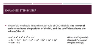
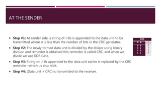
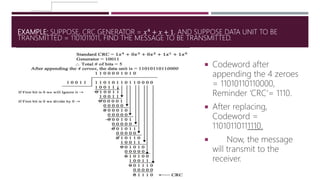
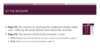
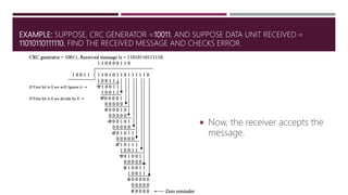
ERROR CONTROL CODING TECHNIQUES
CYCLIC REDUNDANCY CHECK
DONE BY: ENG. SALEH ALRKIYAN | HTTPS://WWW.LINKEDIN.COM/IN/SALRKIYAN
INFORMATION THEORY & CODING
CYCLIC REDUNDANCY CODES
 Cyclic Redundancy Codes (CRCs) provide a first line of defense against data
corruption in many networks. Unfortunately, many commonly used CRC
polynomials provide significantly less error detection capability than they
might. An exhaustive exploration reveals that most previously published CRC
polynomials are either inferior to alternatives or are only good choices for
particular message lengths.
CYCLIC REDUNDANCY CODES
 The cyclic redundancy check, or CRC, is a technique for detecting errors in
digital data, but not for making corrections when errors are detected.
 It is used primarily in data transmission. In the CRC method, a certain number
of check bits, often called a checksum, are appended to the message being
transmitted.
 The receiver can determine whether or not the check bits agree with the data,
to ascertain with a certain degree of probability whether or not an error
occurred in transmission. If an error occurred, the receiver sends a “negative
acknowledgement” (NAK) back to the sender, requesting that the message be
retransmitted.
 The technique is also sometimes applied to data storage devices, such as a
disk drive.
DATA STORING
 Data are stored in bytes, which consist of 8 bits each. Thus any set of data can
be considered as sequence of bytes or bits. In computer communication
usually the bits are considered to be independent and a bit sequence is
limited by the size of data blocks (or frames, packets, datagrams etc.). Thus we
consider the problem to check whether a finite sequence of bits is changed
unintentionally, e.g. by transmission errors or faulty memories.
 Cyclic redundancy check performs a special operation that can be interpreted
as polynomial division. The residual of this division is used as redundancy
information and we will explore in this paper which types of errors can be
detected by this method.
EXPLAINED STEP BY STEP
 First of all, we should know the major rule of CRC which is: The Power of
each term shows the position of the bit, and the coefficient shows the
value of the bit.
AT THE SENDER
 Step #1: At sender side, a string of n 0s is appended to the data unit to be
transmitted where n is less than the number of bits in the CRC generator.
 Step #2: The newly formed data unit is divided by the divisor using binary
division and reminder is obtained this reminder is called CRC, and when we
divide we use XOR Gate.
 Step #3: String on n 0s appended to the data unit earlier is replaced by the CRC
reminder –which us also n bit.
 Step #4: (Data unit + CRC) is transmitted to the receiver.
XOR
A B Y
0 0
0 1
1 0
1 1
0
1
1
0
EXAMPLE: SUPPOSE, CRC GENERATOR = 𝑥4 + 𝑥 + 1, AND SUPPOSE DATA UNIT TO BE
TRANSMITTED = 1101011011, FIND THE MESSAGE TO BE TRANSMITTED.
 Codeword after
appending the 4 zeroes
= 11010110110000,
Reminder ‘CRC’= 1110.
 After replacing,
Codeword =
11010110111110.
 Now, the message
will transmit to the
receiver.
AT THE RECEIVER
 Step #1: The receiver on receiving the codeword, divides (Data
unit + CRC) by the same division and checks the reminder.
 Step #2: The receiver checks if the reminder is zero.
 If Yes, Receiver assume that there is no error in data and and therefore accept it.
 If No, There is an error in data and therefore reject it.
XOR
A B Y
0 0
0 1
1 0
1 1
0
1
1
0
EXAMPLE: SUPPOSE, CRC GENERATOR =10011, AND SUPPOSE DATA UNIT RECEIVED =
11010110111110, FIND THE RECEIVED MESSAGE AND CHECKS ERROR.
 Now, the receiver accepts the
message.
Cyclic redundancy check

Cyclic redundancy check

  • 1.
    ERROR CONTROL CODINGTECHNIQUES CYCLIC REDUNDANCY CHECK DONE BY: ENG. SALEH ALRKIYAN | HTTPS://WWW.LINKEDIN.COM/IN/SALRKIYAN INFORMATION THEORY & CODING
  • 2.
    CYCLIC REDUNDANCY CODES Cyclic Redundancy Codes (CRCs) provide a first line of defense against data corruption in many networks. Unfortunately, many commonly used CRC polynomials provide significantly less error detection capability than they might. An exhaustive exploration reveals that most previously published CRC polynomials are either inferior to alternatives or are only good choices for particular message lengths.
  • 3.
    CYCLIC REDUNDANCY CODES The cyclic redundancy check, or CRC, is a technique for detecting errors in digital data, but not for making corrections when errors are detected.  It is used primarily in data transmission. In the CRC method, a certain number of check bits, often called a checksum, are appended to the message being transmitted.  The receiver can determine whether or not the check bits agree with the data, to ascertain with a certain degree of probability whether or not an error occurred in transmission. If an error occurred, the receiver sends a “negative acknowledgement” (NAK) back to the sender, requesting that the message be retransmitted.  The technique is also sometimes applied to data storage devices, such as a disk drive.
  • 4.
    DATA STORING  Dataare stored in bytes, which consist of 8 bits each. Thus any set of data can be considered as sequence of bytes or bits. In computer communication usually the bits are considered to be independent and a bit sequence is limited by the size of data blocks (or frames, packets, datagrams etc.). Thus we consider the problem to check whether a finite sequence of bits is changed unintentionally, e.g. by transmission errors or faulty memories.  Cyclic redundancy check performs a special operation that can be interpreted as polynomial division. The residual of this division is used as redundancy information and we will explore in this paper which types of errors can be detected by this method.
  • 5.
    EXPLAINED STEP BYSTEP  First of all, we should know the major rule of CRC which is: The Power of each term shows the position of the bit, and the coefficient shows the value of the bit.
  • 6.
    AT THE SENDER Step #1: At sender side, a string of n 0s is appended to the data unit to be transmitted where n is less than the number of bits in the CRC generator.  Step #2: The newly formed data unit is divided by the divisor using binary division and reminder is obtained this reminder is called CRC, and when we divide we use XOR Gate.  Step #3: String on n 0s appended to the data unit earlier is replaced by the CRC reminder –which us also n bit.  Step #4: (Data unit + CRC) is transmitted to the receiver. XOR A B Y 0 0 0 1 1 0 1 1 0 1 1 0
  • 7.
    EXAMPLE: SUPPOSE, CRCGENERATOR = 𝑥4 + 𝑥 + 1, AND SUPPOSE DATA UNIT TO BE TRANSMITTED = 1101011011, FIND THE MESSAGE TO BE TRANSMITTED.  Codeword after appending the 4 zeroes = 11010110110000, Reminder ‘CRC’= 1110.  After replacing, Codeword = 11010110111110.  Now, the message will transmit to the receiver.
  • 8.
    AT THE RECEIVER Step #1: The receiver on receiving the codeword, divides (Data unit + CRC) by the same division and checks the reminder.  Step #2: The receiver checks if the reminder is zero.  If Yes, Receiver assume that there is no error in data and and therefore accept it.  If No, There is an error in data and therefore reject it. XOR A B Y 0 0 0 1 1 0 1 1 0 1 1 0
  • 9.
    EXAMPLE: SUPPOSE, CRCGENERATOR =10011, AND SUPPOSE DATA UNIT RECEIVED = 11010110111110, FIND THE RECEIVED MESSAGE AND CHECKS ERROR.  Now, the receiver accepts the message.