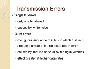
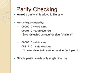
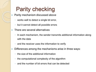
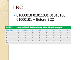
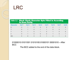
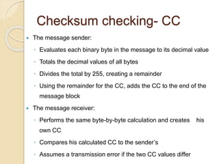
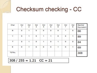
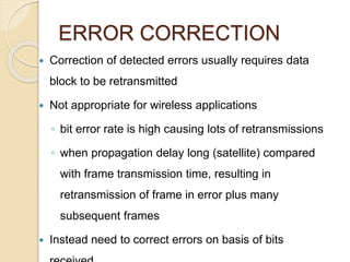
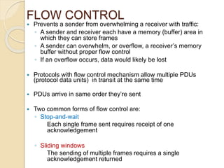
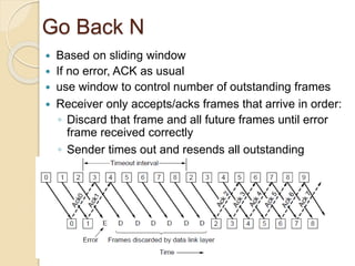
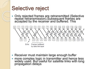
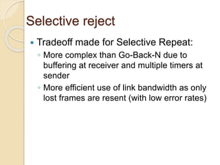
DATA COMMUNICATION
AND NETWORKING
ERROR CORRECTION AND DETECTION
OBJECTIVES
 To identify the types of errors commonly found in
communication networks.
 To Specify the different error prevention
techniques.
 To perform the simple different types of parity
checking
 To understand the error correction process
Transmission Errors
 Single bit errors
◦ only one bit altered
◦ caused by white noise
 Burst errors
◦ contiguous sequence of B bits in which first last
and any number of intermediate bits in error
◦ caused by impulse noise or by fading in wireless
◦ effect greater at higher data rates
Other errors
◦ Impulse noise – electrical interference
◦ White noise – movement of electrons
◦ Attenuation – loss of signal
◦ Crosstalk – signals interfere
 Inter-modulation noise – combination of
frequencies
◦ Delay distortion – data arrives at different times
◦ Line failure – loss of line
ERROR DETECTION
 Errors can result when data is lost, corrupted, or damaged,
making error control critical
 Error control has two components:
◦ Error Detection
◦ Error Correction
Common error detection methods include;
◦ Parity checking
 50% probability of detection
◦ Longitudinal redundancy checking
 98% probability of detection
◦ Checksum checking
 99.6% probability of detection
Parity Bits and Parity Checking
 Parity checking requires the sender
◦ to compute an additional bit
◦ called a parity bit
◦ and to attach it to each character before
sending
 The receiver
◦ removes the parity bit
◦ performs the same computation as the sender
◦ and verifies that the result agrees with the
Parity bits and parity checking
 The parity computation is chosen such that
◦ if one of the bits in the character is damaged in
transit, the receiver's computation will not agree with
the parity bit
◦ the receiver will report that an error occurred.
 There are two forms of parity
◦ even or odd
◦ both the sender and receiver must agree
Parity Checking
 An extra parity bit is added to the byte
 Assuming even parity:
◦ 10000010 – data sent
10000110 - data received
 Error detected on receiver side (single bit)
◦ 10000010 – data sent
10011010 – data received
 No error detected on receiver side (multiple bit)
 Simple parity detects only single bit errors
Parity checking
 Parity mechanism discussed above
◦ works well to detect a single bit error,
◦ but it cannot detect all possible errors
 There are several alternatives
◦ In each mechanism, the sender transmits additional information along
with the data
◦ and the receiver uses the information to verify
 Differences among the mechanisms arise in three ways:
◦ the size of the additional information
◦ the computational complexity of the algorithm
◦ and the number of bit errors that can be detected
Longitudinal Redundancy
checking
 Longitudinal literally means “lengthwise”
 The sender, for each byte in the message, calculates a
parity value, creating an additional block check character
or BCC
◦ As with parity checking, the parity value is odd or even
 The BCC is added to the end of the message block
 The receiver performs the same lengthwise LRC
computation
 If the receiver’s calculated BCC does not equal the
sender’s calculated BCC, the receiver assumes a
LRC
 01000010 01011001 01010100
01000101 – Before BCC
LRC
01000010 01011001 01010100 01000101 00001010 – After
BCC
The BCC added to the end of the data block.
Checksum checking- CC
 The message sender:
◦ Evaluates each binary byte in the message to its decimal value
◦ Totals the decimal values of all bytes
◦ Divides the total by 255, creating a remainder
◦ Using the remainder for the CC, adds the CC to the end of the
message block
 The message receiver:
◦ Performs the same byte-by-byte calculation and creates his
own CC
◦ Compares his calculated CC to the sender’s
◦ Assumes a transmission error if the two CC values differ
Checksum checking - CC
ERROR CORRECTION
 Correction of detected errors usually requires data
block to be retransmitted
 Not appropriate for wireless applications
◦ bit error rate is high causing lots of retransmissions
◦ when propagation delay long (satellite) compared
with frame transmission time, resulting in
retransmission of frame in error plus many
subsequent frames
 Instead need to correct errors on basis of bits
FLOW CONTROL
 Prevents a sender from overwhelming a receiver with traffic:
◦ A sender and receiver each have a memory (buffer) area in
which they can store frames
◦ A sender can overwhelm, or overflow, a receiver’s memory
buffer without proper flow control
◦ If an overflow occurs, data would likely be lost
 Protocols with flow control mechanism allow multiple PDUs
(protocol data units) in transit at the same time
 PDUs arrive in same order they’re sent
 Two common forms of flow control are:
◦ Stop-and-wait
Each single frame sent requires receipt of one
acknowledgement
◦ Sliding windows
The sending of multiple frames requires a single
acknowledgement returned
Flow control
 Reasons for breaking up a block of data
before transmitting:
◦ Limited buffer size of receiver
◦ Retransmission of PDU due to error
requires smaller amounts of data to be
retransmitted
◦ On shared medium, larger PDUs occupy
medium for extended period, causing
Error control requirements
 Error detection
◦ Receiver detects errors and discards PDUs
 Positive acknowledgement
◦ Destination returns acknowledgment of
received, error-free PDUs
 Retransmission after timeout
◦ Source retransmits unacknowledged PDU
 Negative acknowledgement and
retransmission
◦ Destination returns negative acknowledgment to
PDUs in error
Model of frame transmission
Stop and wait
 Source transmits single frame
 Wait for ACK
 If received frame damaged,
discard it
◦ transmitter has timeout
◦ if no ACK within timeout,
retransmit
 If ACK damaged, transmitter
will not recognize it
◦ transmitter will retransmit
◦ receive gets two copies of frame
◦ use alternate numbering and ACK0 / ACK1
Stop and wait
Most efficient for messages containing a few
large
frames that traverse short links.
Requires one acknowledgement for each frame
sent
 pros and cons
◦ Simple
◦ inefficient
Sliding window flow control
 Sender maintains window of frames it can send
◦ Needs to buffer them for possible retransmission
◦ Window advances with next acknowledgements
 Receiver maintains window of frames it can
receive
◦ Needs to keep buffer space for arrivals
◦ Window advances with in-order arrivals
 Allows multiple numbered frames to be in transit
Sliding window flow control
 If two stations exchange data, each needs to
maintain two windows
one for transmit and one for receive
 Each side needs to send the data and
acknowledgments to the other.
Sliding window flow control
• Most efficient for messages containing many small frames
that traverse long links. Allows for one acknowledgement for
multiple frames
Automatic Repeat Request
(ARQ)
 Collective name for such error control
mechanisms, including:
◦ Go back N
◦ Selective reject (selective retransmission)
Go Back N
 Based on sliding window
 If no error, ACK as usual
 use window to control number of outstanding frames
 Receiver only accepts/acks frames that arrive in order:
◦ Discard that frame and all future frames until error
frame received correctly
◦ Sender times out and resends all outstanding
frames
Go Back N
 Tradeoff made for Go-Back-N:
◦ Simple strategy for receiver; needs only 1
frame
◦ Wastes link bandwidth for errors with
large windows; entire window is
retransmitted
 Damaged Frame
◦ error in frame i so receiver rejects frame i
◦ transmitter retransmits frames from i
Selective reject
 Only rejected frames are retransmitted (Selective
repeat retransmission).Subsequent frames are
accepted by the receiver and buffered. This
minimizes retransmission.
 Receiver must maintain large enough buffer
 more complex logic in transmitter and hence less
widely used. But useful for satellite links with long
propagation delays
Selective reject
 Tradeoff made for Selective Repeat:
◦ More complex than Go-Back-N due to
buffering at receiver and multiple timers at
sender
◦ More efficient use of link bandwidth as only
lost frames are resent (with low error rates)

Error detection and correction

  • 1.
  • 2.
    OBJECTIVES  To identifythe types of errors commonly found in communication networks.  To Specify the different error prevention techniques.  To perform the simple different types of parity checking  To understand the error correction process
  • 3.
    Transmission Errors  Singlebit errors ◦ only one bit altered ◦ caused by white noise  Burst errors ◦ contiguous sequence of B bits in which first last and any number of intermediate bits in error ◦ caused by impulse noise or by fading in wireless ◦ effect greater at higher data rates
  • 4.
    Other errors ◦ Impulsenoise – electrical interference ◦ White noise – movement of electrons ◦ Attenuation – loss of signal ◦ Crosstalk – signals interfere  Inter-modulation noise – combination of frequencies ◦ Delay distortion – data arrives at different times ◦ Line failure – loss of line
  • 5.
    ERROR DETECTION  Errorscan result when data is lost, corrupted, or damaged, making error control critical  Error control has two components: ◦ Error Detection ◦ Error Correction Common error detection methods include; ◦ Parity checking  50% probability of detection ◦ Longitudinal redundancy checking  98% probability of detection ◦ Checksum checking  99.6% probability of detection
  • 6.
    Parity Bits andParity Checking  Parity checking requires the sender ◦ to compute an additional bit ◦ called a parity bit ◦ and to attach it to each character before sending  The receiver ◦ removes the parity bit ◦ performs the same computation as the sender ◦ and verifies that the result agrees with the
  • 7.
    Parity bits andparity checking  The parity computation is chosen such that ◦ if one of the bits in the character is damaged in transit, the receiver's computation will not agree with the parity bit ◦ the receiver will report that an error occurred.  There are two forms of parity ◦ even or odd ◦ both the sender and receiver must agree
  • 8.
    Parity Checking  Anextra parity bit is added to the byte  Assuming even parity: ◦ 10000010 – data sent 10000110 - data received  Error detected on receiver side (single bit) ◦ 10000010 – data sent 10011010 – data received  No error detected on receiver side (multiple bit)  Simple parity detects only single bit errors
  • 9.
    Parity checking  Paritymechanism discussed above ◦ works well to detect a single bit error, ◦ but it cannot detect all possible errors  There are several alternatives ◦ In each mechanism, the sender transmits additional information along with the data ◦ and the receiver uses the information to verify  Differences among the mechanisms arise in three ways: ◦ the size of the additional information ◦ the computational complexity of the algorithm ◦ and the number of bit errors that can be detected
  • 10.
    Longitudinal Redundancy checking  Longitudinalliterally means “lengthwise”  The sender, for each byte in the message, calculates a parity value, creating an additional block check character or BCC ◦ As with parity checking, the parity value is odd or even  The BCC is added to the end of the message block  The receiver performs the same lengthwise LRC computation  If the receiver’s calculated BCC does not equal the sender’s calculated BCC, the receiver assumes a
  • 11.
    LRC  01000010 0101100101010100 01000101 – Before BCC
  • 12.
    LRC 01000010 01011001 0101010001000101 00001010 – After BCC The BCC added to the end of the data block.
  • 13.
    Checksum checking- CC The message sender: ◦ Evaluates each binary byte in the message to its decimal value ◦ Totals the decimal values of all bytes ◦ Divides the total by 255, creating a remainder ◦ Using the remainder for the CC, adds the CC to the end of the message block  The message receiver: ◦ Performs the same byte-by-byte calculation and creates his own CC ◦ Compares his calculated CC to the sender’s ◦ Assumes a transmission error if the two CC values differ
  • 14.
  • 15.
    ERROR CORRECTION  Correctionof detected errors usually requires data block to be retransmitted  Not appropriate for wireless applications ◦ bit error rate is high causing lots of retransmissions ◦ when propagation delay long (satellite) compared with frame transmission time, resulting in retransmission of frame in error plus many subsequent frames  Instead need to correct errors on basis of bits
  • 16.
    FLOW CONTROL  Preventsa sender from overwhelming a receiver with traffic: ◦ A sender and receiver each have a memory (buffer) area in which they can store frames ◦ A sender can overwhelm, or overflow, a receiver’s memory buffer without proper flow control ◦ If an overflow occurs, data would likely be lost  Protocols with flow control mechanism allow multiple PDUs (protocol data units) in transit at the same time  PDUs arrive in same order they’re sent  Two common forms of flow control are: ◦ Stop-and-wait Each single frame sent requires receipt of one acknowledgement ◦ Sliding windows The sending of multiple frames requires a single acknowledgement returned
  • 17.
    Flow control  Reasonsfor breaking up a block of data before transmitting: ◦ Limited buffer size of receiver ◦ Retransmission of PDU due to error requires smaller amounts of data to be retransmitted ◦ On shared medium, larger PDUs occupy medium for extended period, causing
  • 18.
    Error control requirements Error detection ◦ Receiver detects errors and discards PDUs  Positive acknowledgement ◦ Destination returns acknowledgment of received, error-free PDUs  Retransmission after timeout ◦ Source retransmits unacknowledged PDU  Negative acknowledgement and retransmission ◦ Destination returns negative acknowledgment to PDUs in error
  • 19.
    Model of frametransmission
  • 20.
    Stop and wait Source transmits single frame  Wait for ACK  If received frame damaged, discard it ◦ transmitter has timeout ◦ if no ACK within timeout, retransmit  If ACK damaged, transmitter will not recognize it ◦ transmitter will retransmit ◦ receive gets two copies of frame ◦ use alternate numbering and ACK0 / ACK1
  • 21.
    Stop and wait Mostefficient for messages containing a few large frames that traverse short links. Requires one acknowledgement for each frame sent  pros and cons ◦ Simple ◦ inefficient
  • 22.
    Sliding window flowcontrol  Sender maintains window of frames it can send ◦ Needs to buffer them for possible retransmission ◦ Window advances with next acknowledgements  Receiver maintains window of frames it can receive ◦ Needs to keep buffer space for arrivals ◦ Window advances with in-order arrivals  Allows multiple numbered frames to be in transit
  • 23.
    Sliding window flowcontrol  If two stations exchange data, each needs to maintain two windows one for transmit and one for receive  Each side needs to send the data and acknowledgments to the other.
  • 24.
    Sliding window flowcontrol • Most efficient for messages containing many small frames that traverse long links. Allows for one acknowledgement for multiple frames
  • 25.
    Automatic Repeat Request (ARQ) Collective name for such error control mechanisms, including: ◦ Go back N ◦ Selective reject (selective retransmission)
  • 26.
    Go Back N Based on sliding window  If no error, ACK as usual  use window to control number of outstanding frames  Receiver only accepts/acks frames that arrive in order: ◦ Discard that frame and all future frames until error frame received correctly ◦ Sender times out and resends all outstanding frames
  • 27.
    Go Back N Tradeoff made for Go-Back-N: ◦ Simple strategy for receiver; needs only 1 frame ◦ Wastes link bandwidth for errors with large windows; entire window is retransmitted  Damaged Frame ◦ error in frame i so receiver rejects frame i ◦ transmitter retransmits frames from i
  • 28.
    Selective reject  Onlyrejected frames are retransmitted (Selective repeat retransmission).Subsequent frames are accepted by the receiver and buffered. This minimizes retransmission.  Receiver must maintain large enough buffer  more complex logic in transmitter and hence less widely used. But useful for satellite links with long propagation delays
  • 29.
    Selective reject  Tradeoffmade for Selective Repeat: ◦ More complex than Go-Back-N due to buffering at receiver and multiple timers at sender ◦ More efficient use of link bandwidth as only lost frames are resent (with low error rates)