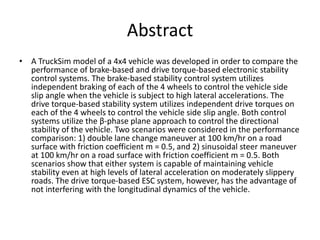
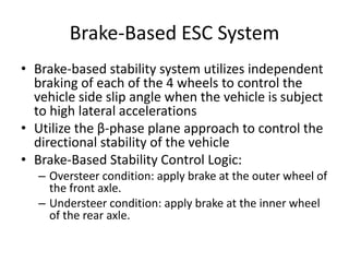
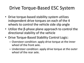
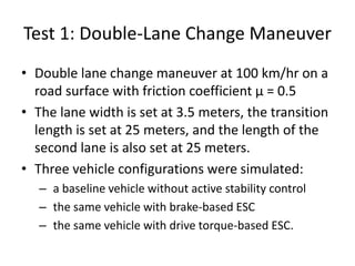
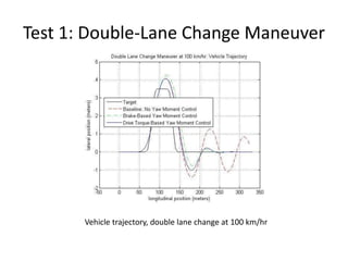
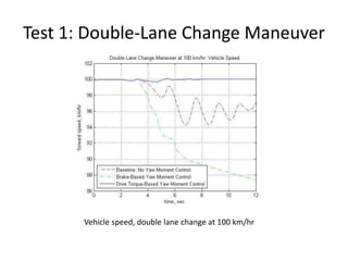
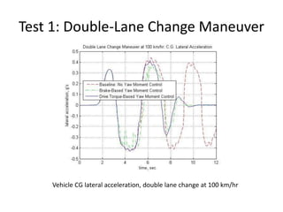
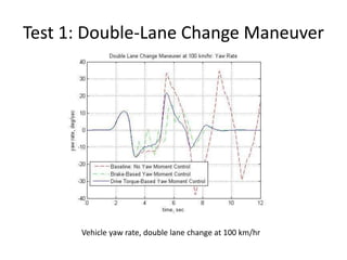
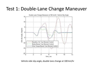
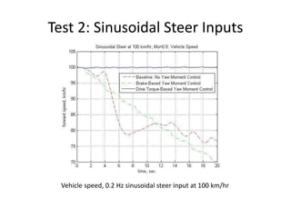
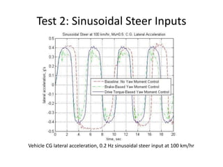
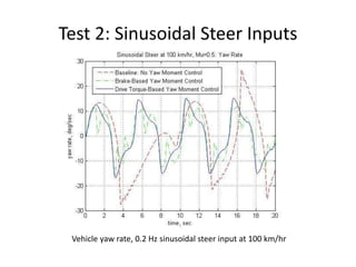
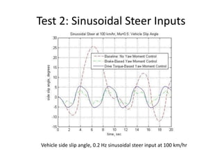
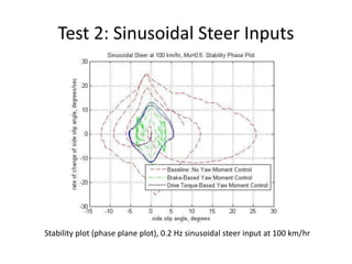
A Continuous Variable Transmission (CVT) is a common transmission system used in low power engines as in ATV or motorcycles. This system is also used by the Baja SAE USB vehicles prototypes and motivated by the willingness to improve the performance of the prototype; I developed a final degree project which aims to describe the dynamic behavior of this system. The result was an algorithm that simulates the dynamic behavior of the vehicle given certain parameters. This project was to opt for mechanical engineering degree, earning an honorable distinction for it.
The Baja SAE Series is an annual competition organized by the Society of Automotive Engineers and has the objective to encourage undergraduate students to design, manufacture and test and All-Terrain vehicle prototype. There are almost 100 participants and it was a good opportunity to put in practice the knowledge acquired in class. In 2010 we achieved the 1st place in design, it has been the highest achievement in the whole team’s history, and it was of course a consequence of our hard work. As Powertrain head I led several tests in order to characterize the dynamical behavior of the vehicle, these developments settles a good base for future generations.
Our third electric Formula SAE car has been designed by our students, thanks to Altair simulation about structural studies. In this way, the software help us building a racing car!
Speakers
Raffaele Martini, Team Leader, Politecnico di Torino
Design of half shaft and wheel hub assembly for racing carRavi Shekhar
The Half - Shaft and Wheel Hub of Formula One racing car was designed taking into consideration one of the popular model of Redbull racing car. The various dimension of shaft and hub were altered to attain maximum factor of safety.
Static structural analysis of suspension arm using finite element methodeSAT Journals
Abstract The function of suspension system is to absorb vibrations due to rough terrains or road disturbances and to provide stability under circumstances like accelerating, cornering, uneven road, braking, loading and unloading etc. Control arm is one of the most important part of the suspension system, as it joins the steering knuckle to the vehicle frame. Also suspension arm is responsible for up and down movement of wheels when hitting bumps. It is also designed to maximize the friction between tire contacts, patch the road surface to provide vehicle stability under any circumstances. It can be seen in many types of the suspensions like wishbone or double wishbone suspensions. Many times it is also called as A-type control arm. In this study control arm was reverse engineered. Reverse engineering refers to the process of obtaining a CAD model from an existing physical part. CAD model was prepared using CATIA v5 software and finite element analysis was done using ANSYS 14.5 software by importing the parasolid file to ANSYS. The model is subjected to loading and boundary conditions and then analyzed using the FEA techniques. The static structural analysis was done to find out the stress, deformation and safety factor of component. The model was meshed using 10-noded tetrahedral elements. Result obtained from the analysis were studied to check whether the design is safe or not. In some cases the stresses becomes more than safe limit. In that case optimization approach is carried out to increase the structural strength of the component. In this case maximum von-misses stress is 211 MPa which is below the yield strength of the material. Keywords – Suspension System, Control Arm, FEA analysis, Reverse Engineering
Forces are generated at the tire contact patch during various maneuvers of the car and transferred to the chassis through the suspension links. Calculating the forces on every link is important to design the suspension system as all the forces from wheel to the chassis are transferred by the suspension linkages. These forces have been calculated for all the links of a double wishbone suspension geometry. The load paths and FBD have been drawn and axial stress in the all the linkages
•SAE Baja is an Inter-colligate off road racing competition where the top engineering colleges in India successfully fabricate and race there all-terrain vehicles.
•The competition has various automotive giants like Mahindra, General motors etc. powering the event.
•The contest challenges each team to function as a firm whose objective is to design, fabricate, market and race off their vehicles that would be evaluated on a variety of manufacturing angles by various professionals from the sponsoring automotive companies.
All Terrain Vehicle specifications and analysis for VIRTUAL BAJA SAE 2016 India. The report is prepared by students of Mechanical Engineering from Tezpur University
Suspension system is the most significant part which heavily affects the vehicle handling performance and ride quality. Because of its structures limit, the passive suspension system can hardly improve the two properties at the same time. Since the advent of active suspension system, it has become the research hot spot. In this review paper we shall see the advantages of the active suspension system over the passive suspensions systems and its incorporation in passenger vehicles.
Anti lock braking control based on bearing deformationvaddamanicharitha
Anti lock braking algorithm based on wheel load by measuring bearing deformation,methodology in finding algorithm ,reconstructing car for measuring wheel load and experimental results.
Team Spark Racing - FSAE Italy & SAE Supra 2015Dhamodharan V
Spark Racing is the official FSAE Team of Sri Venkateswara College of Engineering, Sriperumbudur. Our Student Formula Car built was driven at FSAE Italy, 2015. Emerged 39th in the combustion category among 55 teams.
Four Wheel Active Steering / Without VideosGoodarz Mehr
This presentation gives you more information about Four Wheel Steering systems, physical means to incorporate them and control methods used to determine rear steering angles. In the end, results of our various simulations using CarSim vehicle simulation software and MATLAB Simulink are presented.
An approach to parallel parking and zero turning radius in automobilesIjrdt Journal
Conventional steering mechanism involves either the use of Ackerman or Davis steering systems. The disadvantage associated with these systems is the minimum turning radius that is possible for the steering action. This difficulty that is associated with the conventional methods of steering is eliminated by employing a four wheel steering system. In this system, the wheels connected to the front axles are turned opposite to each other, and so are the wheels connected to the rear axle. The wheels on the on left half vehicle rotate in one direction and the ones on the right half of the vehicle rotate in the opposite direction. This arrangement of the wheels enables the vehicle to turn 360 degrees, without moving from the spot, i.e. the vehicle has zero turning radius. This helps in maneuvering the vehicle in tight spaces such as parking lots and within small compounds.
Cooperative Control Of Drive Motor And Clutch For Gear Shift Of Hybrid Electr...MOHAMMED SAHAD
This focuses on the cooperative control of the drive motor and clutches for the gear shift of a parallel hybrid electric vehicle (HEV) with dual-clutch transmission (DCT). To achieve outstanding gear shift performance, a HEV with DCT powertrain requires sophisticated control of two clutch actuators and power sources. To improve shift quality, a new shift control strategy based on feedback of both speed and torque states is implemented in this slide.
Project presention on four wheels steering system by PARVIND GUPTAParvind Gupta
In this project there are participated four member at college SKYLINE INSTITUTE GREATER NOIDA
About the Project: With the help of this system all four wheels can be turned to any direction with the steering. This can controlled more effectively & also speed of vehicle can be increased & decreased as per requirements.
Hill assist is an automatic system that operates brakes to stop rolling back when it is starting on steep hill. When hill assist system senses vehicle is starting from rest on slope, it automatically keeps footbrake even after you release the pedal by accelerated vehicle using parking brake /hand brake. The hill start assist control helps to increase control on steep grades and prevents from locking. In this hill stop mechanism is also described to prevent car from rolling back.
What is rack and pinion steering mechanismManish Nepal
What Is Rack And Pinion Steering Mechanism? | How Rack And Pinion Steering System Works?
STEERING SYSTEM | WORKING and COMPONENTS
Working of Four Wheel Steering System in Hindi | Advantages, and Disadvantages of 4-Wheel Steering
How Power Steering System Works?
Four steering system is about the maneuvering of the wheel using all four wheel. Which allows the vehicle to take sharp turn at slow speed and decrease the rollover accident danger at higher speed.
Core technology of Hyundai Motor Group's EV platform 'E-GMP'Hyundai Motor Group
What’s the force behind Hyundai Motor Group's EV performance and quality?
Maximized driving performance and quick charging time through high-density battery pack and fast charging technology and applicable to various vehicle types!
Discover more about Hyundai Motor Group’s EV platform ‘E-GMP’!
Ever been troubled by the blinking sign and didn’t know what to do?
Here’s a handy guide to dashboard symbols so that you’ll never be confused again!
Save them for later and save the trouble!
Comprehensive program for Agricultural Finance, the Automotive Sector, and Empowerment . We will define the full scope and provide a detailed two-week plan for identifying strategic partners in each area within Limpopo, including target areas.:
1. Agricultural : Supporting Primary and Secondary Agriculture
• Scope: Provide support solutions to enhance agricultural productivity and sustainability.
• Target Areas: Polokwane, Tzaneen, Thohoyandou, Makhado, and Giyani.
2. Automotive Sector: Partnerships with Mechanics and Panel Beater Shops
• Scope: Develop collaborations with automotive service providers to improve service quality and business operations.
• Target Areas: Polokwane, Lephalale, Mokopane, Phalaborwa, and Bela-Bela.
3. Empowerment : Focusing on Women Empowerment
• Scope: Provide business support support and training to women-owned businesses, promoting economic inclusion.
• Target Areas: Polokwane, Thohoyandou, Musina, Burgersfort, and Louis Trichardt.
We will also prioritize Industrial Economic Zone areas and their priorities.
Sign up on https://profilesmes.online/welcome/
To be eligible:
1. You must have a registered business and operate in Limpopo
2. Generate revenue
3. Sectors : Agriculture ( primary and secondary) and Automative
Women and Youth are encouraged to apply even if you don't fall in those sectors.
In this presentation, we have discussed a very important feature of BMW X5 cars… the Comfort Access. Things that can significantly limit its functionality. And things that you can try to restore the functionality of such a convenient feature of your vehicle.
𝘼𝙣𝙩𝙞𝙦𝙪𝙚 𝙋𝙡𝙖𝙨𝙩𝙞𝙘 𝙏𝙧𝙖𝙙𝙚𝙧𝙨 𝙞𝙨 𝙫𝙚𝙧𝙮 𝙛𝙖𝙢𝙤𝙪𝙨 𝙛𝙤𝙧 𝙢𝙖𝙣𝙪𝙛𝙖𝙘𝙩𝙪𝙧𝙞𝙣𝙜 𝙩𝙝𝙚𝙞𝙧 𝙥𝙧𝙤𝙙𝙪𝙘𝙩𝙨. 𝙒𝙚 𝙝𝙖𝙫𝙚 𝙖𝙡𝙡 𝙩𝙝𝙚 𝙥𝙡𝙖𝙨𝙩𝙞𝙘 𝙜𝙧𝙖𝙣𝙪𝙡𝙚𝙨 𝙪𝙨𝙚𝙙 𝙞𝙣 𝙖𝙪𝙩𝙤𝙢𝙤𝙩𝙞𝙫𝙚 𝙖𝙣𝙙 𝙖𝙪𝙩𝙤 𝙥𝙖𝙧𝙩𝙨 𝙖𝙣𝙙 𝙖𝙡𝙡 𝙩𝙝𝙚 𝙛𝙖𝙢𝙤𝙪𝙨 𝙘𝙤𝙢𝙥𝙖𝙣𝙞𝙚𝙨 𝙗𝙪𝙮 𝙩𝙝𝙚 𝙜𝙧𝙖𝙣𝙪𝙡𝙚𝙨 𝙛𝙧𝙤𝙢 𝙪𝙨.
Over the 10 years, we have gained a strong foothold in the market due to our range's high quality, competitive prices, and time-lined delivery schedules.
5 Warning Signs Your BMW's Intelligent Battery Sensor Needs AttentionBertini's German Motors
IBS monitors and manages your BMW’s battery performance. If it malfunctions, you will have to deal with an array of electrical issues in your vehicle. Recognize warning signs like dimming headlights, frequent battery replacements, and electrical malfunctions to address potential IBS issues promptly.
What Exactly Is The Common Rail Direct Injection System & How Does It WorkMotor Cars International
Learn about Common Rail Direct Injection (CRDi) - the revolutionary technology that has made diesel engines more efficient. Explore its workings, advantages like enhanced fuel efficiency and increased power output, along with drawbacks such as complexity and higher initial cost. Compare CRDi with traditional diesel engines and discover why it's the preferred choice for modern engines.
Fleet management these days is next to impossible without connected vehicle solutions. Why? Well, fleet trackers and accompanying connected vehicle management solutions tend to offer quite a few hard-to-ignore benefits to fleet managers and businesses alike. Let’s check them out!
Why Is Your BMW X3 Hood Not Responding To Release CommandsDart Auto
Experiencing difficulty opening your BMW X3's hood? This guide explores potential issues like mechanical obstruction, hood release mechanism failure, electrical problems, and emergency release malfunctions. Troubleshooting tips include basic checks, clearing obstructions, applying pressure, and using the emergency release.
Things to remember while upgrading the brakes of your carjennifermiller8137
Upgrading the brakes of your car? Keep these things in mind before doing so. Additionally, start using an OBD 2 GPS tracker so that you never miss a vehicle maintenance appointment. On top of this, a car GPS tracker will also let you master good driving habits that will let you increase the operational life of your car’s brakes.
"Trans Failsafe Prog" on your BMW X5 indicates potential transmission issues requiring immediate action. This safety feature activates in response to abnormalities like low fluid levels, leaks, faulty sensors, electrical or mechanical failures, and overheating.
What Does the PARKTRONIC Inoperative, See Owner's Manual Message Mean for You...Autohaus Service and Sales
Learn what "PARKTRONIC Inoperative, See Owner's Manual" means for your Mercedes-Benz. This message indicates a malfunction in the parking assistance system, potentially due to sensor issues or electrical faults. Prompt attention is crucial to ensure safety and functionality. Follow steps outlined for diagnosis and repair in the owner's manual.
What Does the PARKTRONIC Inoperative, See Owner's Manual Message Mean for You...
Brake based and Drive Torque-based Electronic Stability Control Systems
1. COMPARISON OF BRAKE-BASED AND DRIVE
TORQUE-BASED ELECTRONIC STABILITY
CONTROL SYSTEMS ON 4X4 VEHICLES WITH
INDEPENDENT SUSPENSION SYSTEMS
Ragnar Ledesma
2007
2. Abstract
• A TruckSim model of a 4x4 vehicle was developed in order to compare the
performance of brake-based and drive torque-based electronic stability
control systems. The brake-based stability control system utilizes
independent braking of each of the 4 wheels to control the vehicle side
slip angle when the vehicle is subject to high lateral accelerations. The
drive torque-based stability system utilizes independent drive torques on
each of the 4 wheels to control the vehicle side slip angle. Both control
systems utilize the β-phase plane approach to control the directional
stability of the vehicle. Two scenarios were considered in the performance
comparison: 1) double lane change maneuver at 100 km/hr on a road
surface with friction coefficient m = 0.5, and 2) sinusoidal steer maneuver
at 100 km/hr on a road surface with friction coefficient m = 0.5. Both
scenarios show that either system is capable of maintaining vehicle
stability even at high levels of lateral acceleration on moderately slippery
roads. The drive torque-based ESC system, however, has the advantage of
not interfering with the longitudinal dynamics of the vehicle.
4. Vehicle Model Description
• The TruckSim model represents a 4x4 JLTV vehicle
loaded at 12,000 lbs per axle. The TruckSim
model consists of rigid bodies for the sprung
mass and unsprung masses, and includes
independent suspension compliance and
kinematics, and Pacejka tire models for vehicle
handling performance prediction. The model of
the drive train system consists of a static engine
torque map and torque balance equations for the
transmission, transfer case and differentials.
5. Brake-Based ESC System
• Brake-based stability system utilizes independent
braking of each of the 4 wheels to control the
vehicle side slip angle when the vehicle is subject
to high lateral accelerations
• Utilize the β-phase plane approach to control the
directional stability of the vehicle
• Brake-Based Stability Control Logic:
– Oversteer condition: apply brake at the outer wheel of
the front axle.
– Understeer condition: apply brake at the inner wheel
of the rear axle.
6. Drive Torque-Based ESC System
• Drive torque-based stability system utilizes
independent drive torques on each of the 4
wheels to control the vehicle side slip angle
• Utilize the β-phase plane approach to control the
directional stability of the vehicle
• Drive Torque-Based Stability Control Logic:
– Oversteer condition: apply drive torque at the inner
wheel of the front axle.
– Understeer condition: apply drive torque at the outer
wheel of the rear axle.
7. Test 1: Double-Lane Change Maneuver
• Double lane change maneuver at 100 km/hr on a
road surface with friction coefficient μ = 0.5
• The lane width is set at 3.5 meters, the transition
length is set at 25 meters, and the length of the
second lane is also set at 25 meters.
• Three vehicle configurations were simulated:
– a baseline vehicle without active stability control
– the same vehicle with brake-based ESC
– the same vehicle with drive torque-based ESC.
8. Test 1: Double-Lane Change Maneuver
Vehicle trajectory, double lane change at 100 km/hr
9. Test 1: Double-Lane Change Maneuver
Vehicle speed, double lane change at 100 km/hr
10. Test 1: Double-Lane Change Maneuver
Vehicle CG lateral acceleration, double lane change at 100 km/hr
11. Test 1: Double-Lane Change Maneuver
Vehicle yaw rate, double lane change at 100 km/hr
12. Test 1: Double-Lane Change Maneuver
Vehicle side slip angle, double lane change at 100 km/hr
13. Test 1: Double-Lane Change Maneuver
Steering wheel angle, double lane change at 100 km/hr
14. Test 1: Double-Lane Change Maneuver
Stability plot (phase plane plot), double lane change at 100 km/hr
15. Test 2: Sinusoidal Steer Inputs
• Sinusoidal steer inputs at 100 km/hr on a road
surface with friction coefficient μ = 0.5
• 0.2 Hz sinusoidal steer input (90 degree
steering wheel angle)
• Three vehicle configurations were simulated:
– a baseline vehicle without active stability control
– the same vehicle with brake-based ESC
– the same vehicle with drive torque-based ESC.
16. Test 2: Sinusoidal Steer Inputs
Vehicle trajectory, 0.2 Hz sinusoidal steer input at 100 km/hr
17. Test 2: Sinusoidal Steer Inputs
Vehicle speed, 0.2 Hz sinusoidal steer input at 100 km/hr
18. Test 2: Sinusoidal Steer Inputs
Vehicle CG lateral acceleration, 0.2 Hz sinusoidal steer input at 100 km/hr
19. Test 2: Sinusoidal Steer Inputs
Vehicle yaw rate, 0.2 Hz sinusoidal steer input at 100 km/hr
20. Test 2: Sinusoidal Steer Inputs
Vehicle side slip angle, 0.2 Hz sinusoidal steer input at 100 km/hr
21. Test 2: Sinusoidal Steer Inputs
Stability plot (phase plane plot), 0.2 Hz sinusoidal steer input at 100 km/hr
22. Conclusions
• Either brake-based or drive torque-based ESC system is
capable of maintaining vehicle stability even at high levels of
lateral acceleration on moderately slippery roads.
• The drive torque-based ESC system has the advantage of not
interfering with the longitudinal dynamics of the vehicle.
• Analysis of the control logic leads one to infer that in
situations involving very high lateral acceleration and
significant transfer of vertical load from the inner wheel to the
outer wheel, the control yaw moment due to drive torque-
based ESC systems can be limited by the amount of traction
capacity at the lightly loaded inner wheel.
• In this extreme case, the brake-based stability control system
can be expected to provide a better performance.
23. Conclusions (continued)
• A combination of brake-based and drive torque-based stability
control system can provide an even better performance compared
to the stand-alone systems.
• With a combined system, the stability control can be provided by
the drive torques when the magnitude of the required corrective
yaw moment is relatively small.
• If the required corrective yaw moment is relatively large, a part of
the corrective yaw moment will be provided by the drive torque,
and the remainder will be produced by the appropriately braked
wheel.
• In this manner, the longitudinal dynamics of the vehicle will be
minimally affected by the stability control system at moderate
levels of lateral acceleration and vehicle stability is assured at
extreme levels of lateral acceleration.