Download as PDF, PPTX


![T = (π/16) x τ x (do)3 x [ 1 – (di / do)4]
We have, k = di / do = 5
So, 2758.665 = (3.14/16) x 0.62x 109 x (do)3 [ 1 – (1/5)4]
do3 = 22882.115
do = 28.39 mm
Or, do = 29 mm.
Therefore, di = 29/5
di = 5.66 mm.
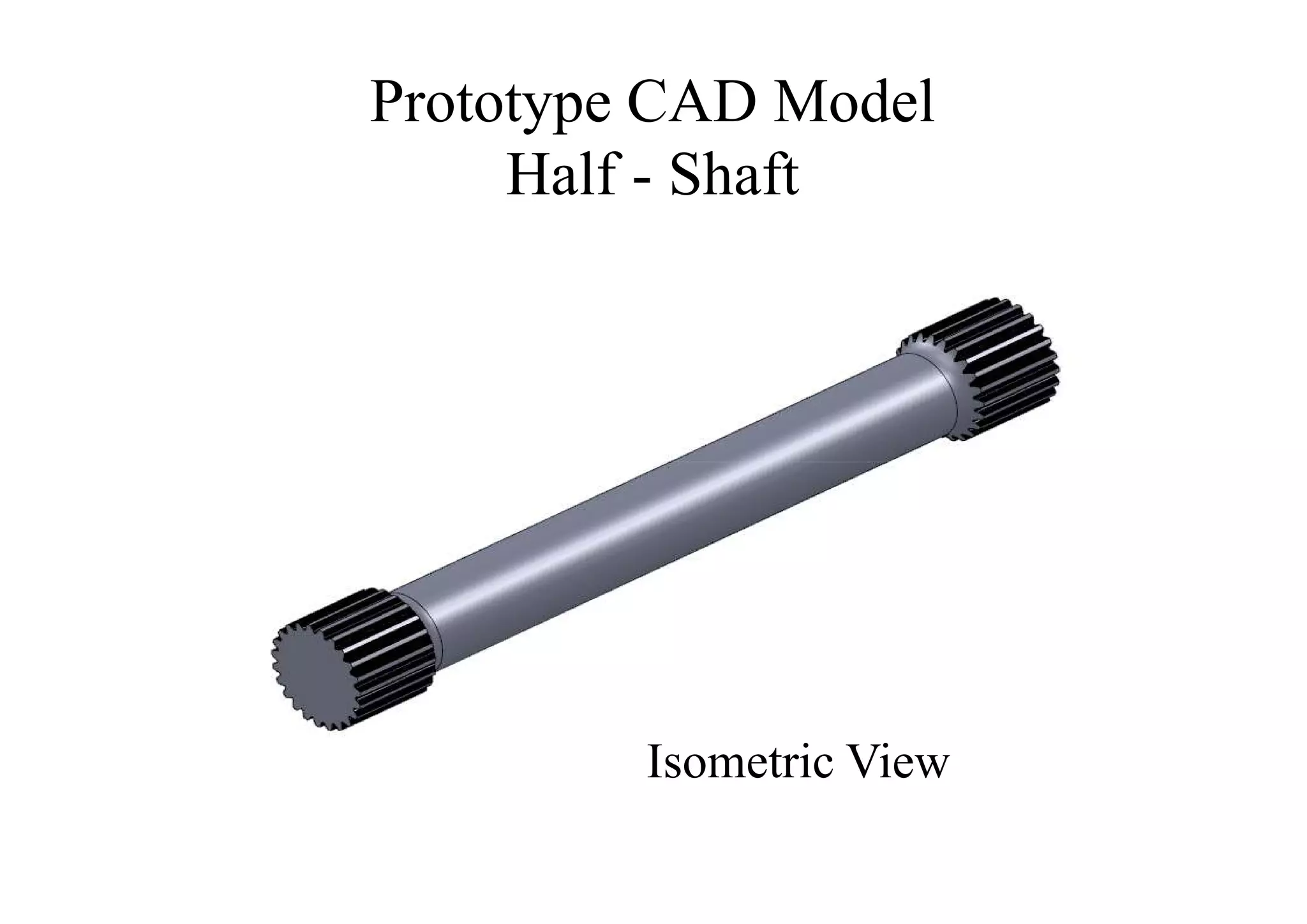
From the design calculation we find that the required external and internal
diameter of the half – shaft as per the specified engine parameters and given
conditions is 29 mm and 5.6 mm.](https://image.slidesharecdn.com/designofhalf-shaftandwheelhubassemblyforracingcar-120531232538-phpapp01/75/Design-of-half-shaft-and-wheel-hub-assembly-for-racing-car-22-2048.jpg)


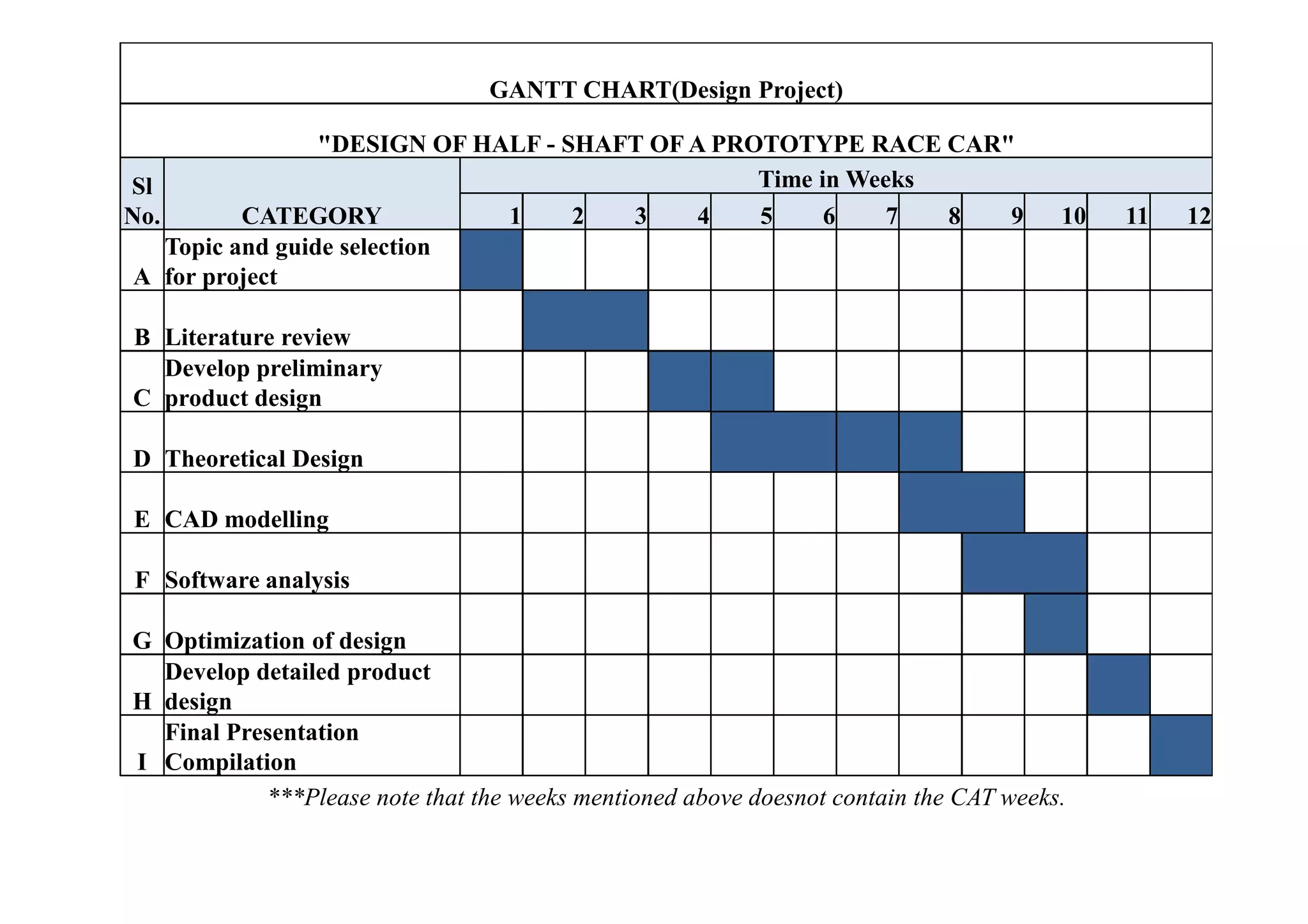


The document details the design project for the half-shaft and rear wheel hub assembly of a Formula 1 race car, aiming for stability and minimal weight to enhance performance. Key design considerations included material selection, stress analysis, and adherence to parameters for optimal functionality under racing conditions. The project culminated in using CAD modeling and finite element analysis to validate designs, with calculations supporting the specifications established for the components.