Downloaded 154 times

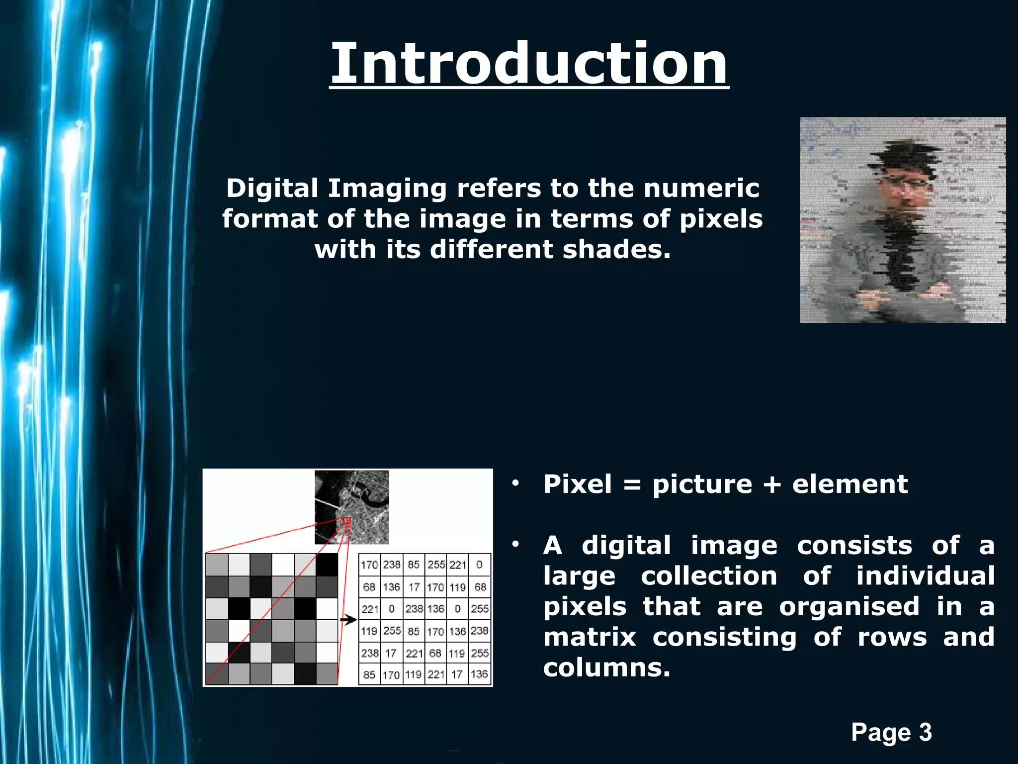
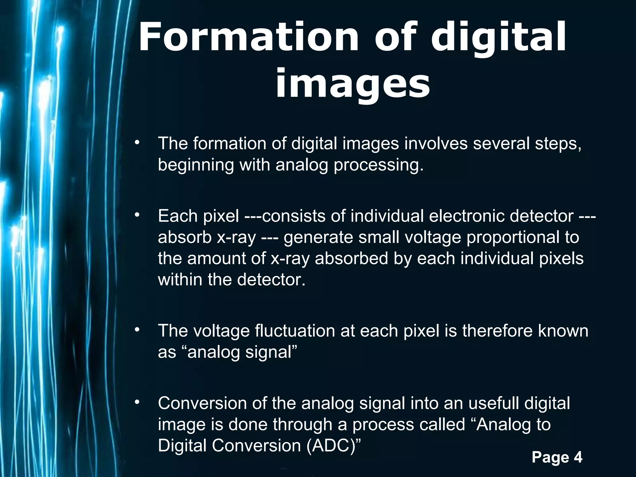


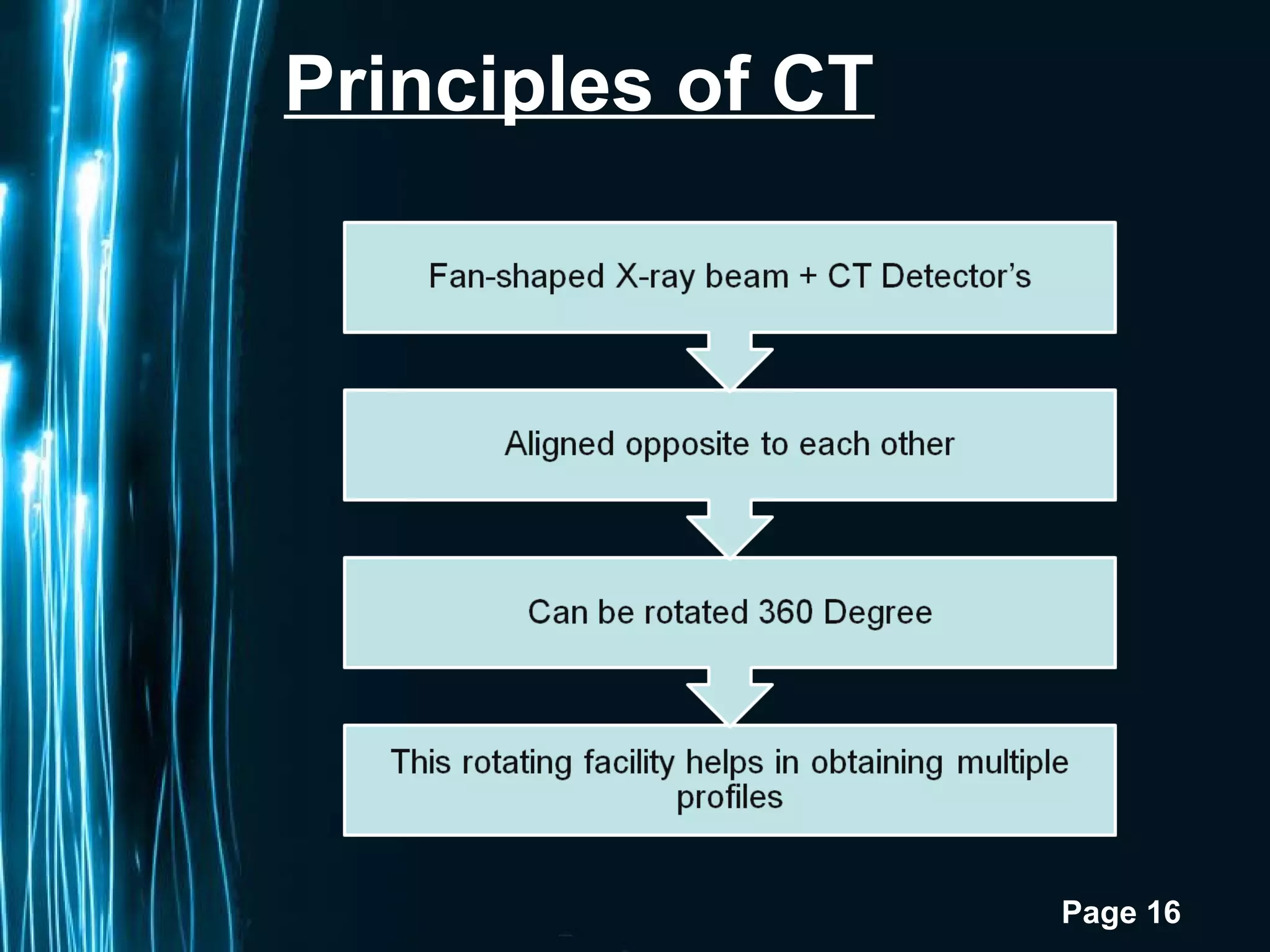


Digital imaging involves converting analog x-ray signals into digital images. This document discusses various digital imaging receptors and techniques. CCD and CMOS detectors convert x-ray exposure into electric signals. DSR produces images of changes by subtracting baseline images from follow-up images. PSP plates use stimulated luminescence to form digital images. CBCT and CT use x-rays to create 3D volumetric images but CBCT has lower radiation dose. MRI uses strong magnetic fields and radio waves to form images based on the magnetic properties of hydrogen atoms and does not use radiation. Each technique has advantages and limitations for various dental and medical applications.


