
More Related Content
What's hot
What's hot (19)
Similar to Embedded System[586]
Similar to Embedded System[586] (20)
Recently uploaded
Recently uploaded (20)
Embedded System[586]
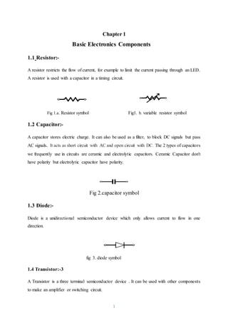
- 1. 1 Chapter 1 Basic Electronics Components 1.1 Resistor:- A resistor restricts the flow of current, for example to limit the current passing through an LED. A resistor is used with a capacitor in a timing circuit. Fig 1.a. Resistor symbol Fig1. b. variable resistor symbol 1.2 Capacitor:- A capacitor stores electric charge. It can also be used as a filter, to block DC signals but pass AC signals. It acts as short circuit with AC and open circuit with DC. The 2 types of capacitors we frequently use in circuits are ceramic and electrolytic capacitors. Ceramic Capacitor don't have polarity but electrolytic capacitor have polarity. Fig 2.capacitor symbol 1.3 Diode:- Diode is a unidirectional semiconductor device which only allows current to flow in one direction. fig 3. diode symbol 1.4 Transistor:-3 A Transistor is a three terminal semiconductor device . It can be used with other components to make an amplifier or switching circuit.
- 2. 2 There are two types of transistor:- 1. NPN transistor 2. PNP transistor Fig .4 a. NPN transistor Fig 4.b. PNP transistor 1.5 LED (Light Emitting Diode):- LED (Light Emitting Diode) is a transducer which converts electrical energy to light frequently used to display the outputs at various stages of the circuit. It is essentially a Diode with the energy released in the form of photons due to electron transitions falling in the visible region. It glows only in fwd bias mode i.e. with p junction connected to +ve voltage and n junction to negative. Diodes are essentially low power devices. The current through the LED should be less than 10mA.Hence always put a 220 ohm resistor in series with the LED. Voltage rating =2v to 3v and current rating =10mA. fig 5. led symbol 1.6 LCD (Liquid Crystal Display):- LCD (Liquid Crystal Display) is a device that use to display alphanumeric digit. LCD screen is an electronic display module and find a wide range of applications. A 16x2 LCD display is very basic module and is very commonly used in various devices and circuits. Basic two types of LCD:- 1. Alphanumeric LCD:-This type of LCD use to display alphanumeric digit. 2. Graphic lcd :-This type of LCD use to display graphical representation.
- 3. 3 Based on size:- 1. 16x1 2. 16x2 3. 20x1 4. 20x2 etc. In 16x2:- 16-number of column 2-number of row lcd pixel is block on per unit use for resolution. Addressing:- Row1 : 0x80 ----------------------------------------------------------0x8f, R0w2 :0xc0-----------------------------------------------------------0xcf. 16 x2 LCD consists two controller one for address and second for data. Fig 6:-16x2 LCD pin configuration :- VSS - Ground VDD - pixel voltage connected with VDD VEE - brightness controlling pin connected with potentiometer. RS : Select Register There are two important register inside the LCD. The RS pin is used for their Selection as follow . If RS=0,the instruction command code register is selected, allowing the user to send a command such as clear display, cursor at home etc. If RS=1, the data register is selected , allowing the user to send to de displayed on the LCD.
- 4. 4 RW: Read/Write R/W input allow to user to write information to the LCD or read information from it. R/W=1 when reading; R/W=0 when writing. EN :Enable The enable pin is used by the LCD to letch information presented to its data pins. It is generally High ti low transition. D1-D7 = data pins Table 1.LCD Command:- Command Use 0x01 Clear screen 0x02 Home screen 0x28 4-bit mode 0x38 8-bit mode 0x80 First pixel 0x0c Display on, cursor off 0x0e Display on, cursor off 0x0f Display on cursor blinking 0x04 Shift the cursor to left 0x06 Shift the cursor to right
- 5. 5 0x1c Shift data towards to left 0x18 Shift data towards to right 1.7 Seven Segment Display(SSD):- Seven segment display is the array of 8 led that have been combined into one case to make a convenient device for displaying numbers and some letters. The seven LEDs in the seven segment display are labeled with the letters A, B, C, D, E. F and G as indicated below. there are two type of seven segment. 1. Common Cathode (CC)-common of all led connected with ground. for led ON=1, for led OFF=0. 2. Common Anode (CA)- common of all led connected with VCC. for led ON=0, for led OFF=1. fig 7:-Seven Segment Table 2.Code for display numeric digit:- Common Cathode Common Anode Digit Binary Hexadecimal Binary Hexadecimal
- 6. 6 0 0b00111111 0x3f 0b11000000 0xc0 1 0b00000110 0x06 0b11111001 0xf9 2 0b01011011 0x5b 0b10100100 0xa4 3 0b01001111 0x4f 0b10110000 0xb0 4 0b01100110 0x66 0b10011001 0x99 5 0b01101101 0x6d 0b10010010 0x92 6 0b01111101 0x7d 0b10000010 0x82 7 0b00000111 0x07 0b11111000 0xf8 8 0b01111111 0x7f 0b10000000 0x80 9 0b01101111 0x6f 0b10010000 0x90 1.8 Integrate Circuit (IC):- ICs or Integrated Circuits are packaged circuits designed for some fixed purpose. An IC has its fixed IC name/number that can be used to get catalog of its functions and pin configuration. ICs come in various sizes and packages depending upon the purpose. 1.8.1 Voltage Regulated IC :- Voltage regulator IC use for fixed output voltage. it is three pin IC .series of voltage regulator Ic is 78xx. The 78XXseries of three-terminal positive regulator are available in the TO-220/D- PAK package and with several fixed output voltages, making them useful in a wide range of
- 7. 7 applications. Each type employs internal current limiting, thermal shut down and safe operating area protection, making it essentially indestructible. If adequate heat sinking is provided, they can deliver over 1A output current. Although designed primarily as fixed voltage regulators, these devices can be used with external components to obtain adjustable voltages and currents. 1.8.2 7805 Voltage Regulated IC :- 7805 voltage regulator is used to get +5 V output out of a higher voltage supply (7.5V-20V).We use adapter’s supply to generate +5V here. Connect the gnd and +12V of adapter to the pins as shown and get +5V directly as an output out of the 3rd pin. Current up to 0.5 A can be obtained from thisregulator without any significant fall in voltage level. Fig 8:-7805 regulated IC
- 8. 8 Chapter 2 Embedded System 2.1 Introduction to Embedded System An Embedded system is a combination of hardware & software that specifically designed for particular purpose. This reduces human effort to a great extent. A single chip contains both hardware and software. Definition of Embedded System:- • A combination of hardware and software which together form a component of a larger machine. • An example of an embedded system is a microprocessor that controls an automobile engine. • An embedded system is designed to run on its own without human intervention, and may be required to respond to events in real time. 2.2 Application of Embedded System 1. TV 8. electric tooth brush 2. stereo 9. oven / rice or bread cooker 3. remote control 10. watch 4. phone / mobile phone 11. alarm clock 5. refrigerator 12. electronic musical instruments 6. microwave 13. electronic toys (stuffed animals, handheld toys, etc.) 7. washing machine 14. medical home equipment (e.g. blood pressure, thermometer)
- 9. 9 2.3 Introduction to Microcontroller 2.3.1 What is microcontroller . Microcontroller is a programmable integrated device that use for a specific purpose. It have external register, timer and counter for processing. 2.3.2 Microcontroller classification :- 2.3.2.1 Based on bit a. 4-bit (it can process on maximum 4-bit data) b. 8-bit (it can process on maximum 8-bit data) c. 16-bit (it can process on maximum 16-bit data) d. 32-bit (it can process on maximum 32-bit data) 2.3.2.2 Based on memory a. Embedded memory :-It is a permanent memory. one time data write it cannot be erase. b. External memory:-In this data can be erase. 2.3.2.3 Based on Architecture a. Harvard :-It consists two buses first for address and second for data. b. Von-Neumann :-It consist only single bus that first work as address bus and after data bus. 2.3.2.4. Based on Instruction Set a. RISC (Reduced Instruction Set Computing) :-It follow the pipelining concept. Pipelining concept:-In this two data are in process at a time.data1 is executing and data2 is fetching at a time . b. CISC (Complex Instruction Set Computing ) :-In this one data in process at a time. 2.4 Programmer Programmer Basically Consists two parts:- 1. Hardware: to connect microcontroller
- 10. 10 Hardware depends on the communication port we are using in our computer like Serial, Parallel or USB etc. 2. Software: to open hex file on our computer some famous software are: a. Sina Prog (Serial) b. Atmel Studio (Support Atmel's hardware) c. USB-ASP (USB) d. ISIS: Proteus (Schematic design of Circuit) 2.5 Introduction to Atmega16 Microcontroller Atmega16 microcontroller is AVR family microcontroller made by the Atmel company and consists mega series. The ATmega16 is a low-power CMOS8-bit microcontroller based on the AVR enhanced RISC architecture. .It is a 40 pin IC follow DIP (dual in line package).voltage rating =5v(3.5-5v) and current rating=20mA. 2.5.1 Feature Advanced RISC Architecture Up to 16 MIPS Throughput at 16 MHz 16K Bytes of In-System Self-Programmable Flash 512 Bytes EEPROM 1K Byte Internal SRAM 32 Programmable I/O Lines In-System Programming by On-chip Boot Program 8-channel, 10-bit ADC Two 8-bit Timer/Counters with Separate Prescalers and Compare Modes One 16-bit Timer/Counter with Separate Prescaler, Compare Mode, and Capture Four PWM Channels
- 11. 11 Programmable Serial USART Master/Slave SPI Serial Interface Byte-oriented Two-wire Serial Interface Programmable Watchdog Timer with Separate On-chip Oscillator External and Internal Interrupt Sources . 2.5.2 Pin configuration Fig 9. Atmega16 pin Diagram 2.5.3 Pin Description VCC: Digital supply voltage. (+5V) GND: Ground. (0 V) Note there are 2 ground Pins. Port A (PA7-PA0)
- 12. 12 Port A serves as the analog inputs to the A/D Converter. Port A also serves as an 8-bit bidirectional I/O port, if the A/D Converter is not used. When pins PA0 to PA7 are used as inputs and are externally pulled low, they will source current if the internal pull-up resistors are activated. The Port A pins are tri-stated when a reset condition becomes active, even if the clock is not running. PortB(PB7-PB0) Port B is an 8-bit bi-directional I/O port with internal pull-up resistors (selected for each bit). Port B also serves the functions of various special features of the ATmega16 . Port C (PC7 - PC0) Port C is an 8-bit bi-directional I/O port with internal pull-up resistors (selected for each bit Port D (PD7 - PD0) Port D is an 8-bit bi-directional I/O port with internal pull-up resistors (selected for each bit). Port D also serves the functions of various special features of the ATmega16 . RESET: Reset Input. A low level on this pin for longer than the minimum pulse length will generate a reset, even if the clock is not running. XTAL1: External oscillator pin 1 XTAL2: External oscillator pin 2 AVCC: AVCC is the supply voltage pin for Port A and the A/D Converter AREF: AREF is the analog reference pin for the A/D Converter 2.5.4 Registers All the configuration in microcontroller is set through 8-bit location on RAM of the microcontroller is called register. the register size of this microcontroller is 8 bit ,so it is called 8 bit microcontroller. these register store controller data temporary at operation time.
- 13. 13 2.5.5 Input Output port Input output function are set by three Register for each PORT. these resister are: 1. DDRX (Data Direction Register):- DDR use to define that device PORT use as input or output. It is a 8-bit register. If we want to make Port pin as input bit is set 0 and to make the output bit set to 1. 2. PORTX (PORTX Data Register):- PORT Register use for assign logic either high (1) or low (0). 3.PIN Register:- The PIN register is used to read the value of a PORT. If a pin is set as a input then corresponding bit on PIN register is,0 for low input and 1 is for high input. We can only read bits of the PINX register; can never write on that as it is meant for reading the value of PORT.
- 14. 14 Chapter 3 UART Communication Protocol 3.1 Introduction to Communication Communication is a process in which we exchange information between two endsor send information from one end to another end. Communication is a Process to exchange data between two or more devices. 3.2 Types of communication:- 1. Duplex communication- this type of comm. is one way comm. means transmitting end transmit signal and receiving end receive. Broadcast comm. is Duplex type comm. Tx Rx Fig 10.Duplex Communication 2. Half Duplex Communication:- In half duplex communication both end consists transmitting and receiving part but at a time one end transmit signal Other end receive. Tx Rx Rx Tx Fig 11.Half DuplexCommunication 3. Full Duplex Communication:- This is two way comm. In full duplex comm. we can transmit signal from both end but the probability of error is high. Tx Rx Tx Rx Fig 12.Full DuplexCommunication
- 15. 15 4. Parallel Communication:- In parallel comm. the data required data lines equal to data bit. parallel comm. fast compare to serial communication. Fig 13. Parallel Communication 5.Serial Communication:- In serial comm. the data is send by bit by bit. It required two data lines one for transmission and second for receiving the data. It is better than the parallel communication and slow compare to parallel communication. It is acknowledgement comm. system. O U T P U T C O N T R O L L E R
- 16. 16 Rx CONT- ROLLER Tx Fig 14. Serial Communication 3.3 Communication Protocols:- 1.USART (Universal Synchronous Asynchronous Receiver and Transmission) The Universal Synchronous and Asynchronous serial Receiver and Transmitter (USART) is a highly flexible serial communication device. The main features are: • Full Duplex Operation (Independent Serial Receive and Transmit Registers) • Asynchronous or Synchronous Operation • Master or Slave Clocked Synchronous Operation 2.UART (Universal Asynchronous Reception and Transmission) These protocols are based on serial communication. Computer use RS-232 protocol to communicate or transfer data from one device to another. 3.4 UART Communication Protocol & It's Register 1. UCSRA (UART Control & Status Register A) 2. UCSRB ( UART Control & Status Register B) Tx OUTPUT Rx
- 17. 17 3. UCSRC (UART Control & Status Register C) 4. UDR (UART Data Register) 5. UBRRL (UART Baud Rate Register Low) 6. UBRRH (UART Baud Rate Register High) UDR:- UDR receive data from pc or other devices and hold data for processing. This is 8-bit register. PC Tx UDR Tx Controller Fig 15. UDR Process UBRR:- UBRR is a 16-bit register divided into two registers UART Baud Rate Register Low and Baud Rate Register High because Atmega16 is 8-bit controller. Baud Rate:- number of data packets transmitted in one second. Bit Rate:- number of data bit (0/1) transmitted in one second. standard baud rate for UART is 9600 and value for UBRRL is 12. UCSRA, B & C:- these registers are 8 bit register use for data controlling ,status and processing of data. 1. UCSRA (UART Control & Status Register A):- UCSRA RXC TXC UDRE FE DOR PE U2X MPCM
- 18. 18 Read/write R R/W R R R R R/W R/W initial value 0 0 1 0 0 0 0 0 • Bit 7 – RXC: UART Receive Complete This flag bit is set when there are unread data in the receive buffer and cleared when the receive buffer is empty(that is, does not contain any unread data).If the receiver is disabled, the receive buffer will be flushed and consequently the RXC bit will become zero. The RXC Flag an be used to generate a Receive Complete interrupt . • Bit 6 – TXC: UART Transmit Complete This flag bit is set when the entire frame in the transmit Shift Register has been shifted out and there are no new data currently present in the transmit buffer (UDR). The TXC Flag bit is automatically cleared when a transmit complete interrupt is executed, or it can be cleared by writing a one to its bit location. The TXC Flag can generate a Transmit Complete interrupt . • Bit 5 – UDRE: UART Data Register Empty The UDRE Flag indicates if the transmit buffer (UDR) is ready to receive new data. If UDRE is one, the buffer is empty, and therefore ready to be written. The UDRE Flag can generate a Data Register empty Interrupt . UDRE is set after a reset to indicate that the transmitter is ready. • Bit 4 – FE: Frame Error This bit is set if the next character in the receive buffer had a Frame Error when received. • Bit 3 – DOR: Data Over Run This bit is set if a Data Over Run condition is detected. Always set this bit to zero when writing to UCSRA. • Bit 2 – PE: Parity Error
- 19. 19 This bit is set if the next character in the receive buffer had a Parity Error when received and the parity checking was enabled at that point . This bit is valid until the receive buffer (UDR) is read. Always set this bit to zero when writing to UCSRA. • Bit 1 – U2X: Double the UART Transmission Speed This bit only has effect for the asynchronous operation. Write this bit to zero when using synchronous operation. • Bit 0 – MPCM: Multi-processor Communication Mode This bit enables the Multi-processor Communication mode. 2. UCSRB ( UART Control & Status Register B):- read/write R/W R/W R/W R/W R/W R/W R R/W initial value 0 0 0 1 1 0 0 0 • Bit 7 – RXCIE: RX Complete Interrupt Enable Writing this bit to one enables interrupt on the RXC Flag. • Bit 6 – TXCIE: TX Complete Interrupt Enable Writing this bit to one enables interrupt on the TXC Flag • Bit 5 – UDRIE: USART Data Register Empty Interrupt Enable Writing this bit to one enables interrupt on the UDRE Flag. A Data Register Empty Interrupt will be generated only if the UDRIE bit is written to one. RXCIE TXCIE UDRIE RXEN TXEN UCSZ2 RXB8 TXB8
- 20. 20 • Bit 4 – RXEN: Receiver Enable Writing this bit to one enables the UART Receiver • Bit 3 – TXEN: Transmitter Enable Writing this bit to one enables the UART Transmitter. The Transmitter will override normal port operation for the TxD pin when enabled • Bit 2 – UCSZ2: Character Size The UCSZ2 bits combined with the UCSZ1:0 bit in UCSRC sets the number of data bits (Character Size) in a frame the receiver and transmitter use. • Bit 1 – RXB8: Receive Data Bit 8 RXB8 is the ninth data bit of the received character when operating with serial frames with nine data bits. Must be read before reading the low bits from UDR. • Bit 0 – TXB8: Transmit Data Bit 8 TXB8 is the ninth data bit in the character to be transmitted when operating with serial frames with nine data bits. Must be written before writing the low bits to UDR. 3. UCSRC (UART Control & Status Register C):- UCSRB read/write R/W R/W R/W R/W R/W R/W R/W R/W initial value 1 0 0 0 0 1 1 0 • Bit 7 – URSEL: Register Select This bit selects between accessing the UCSRC or the UBRRH Register. It is read as one when URSEL UMSEL UPM1 UPM0 USBS UCSZ1 UCSZ0 UCSPOL
- 21. 21 reading UCSRC. The URSEL must be one when writing the UCSRC. • Bit 6 – UMSEL: UART Mode Select This bit selects between Asynchronous and Synchronous mode of operation. • Bit 5:4 – UPM1:0: Parity Mode These bits enable and set type of parity generation and check. If enabled, the transmitter will automatically generate and send the parity of the transmitted data bits within each frame. The Receiver will generate a parity value for the incoming data and compare it to the UPM0 setting. If a mismatch is detected, the PE Flag in UCSRA will be set. • Bit 3 – USBS: Stop Bit Select This bit selects the number of Stop Bits to be inserted by the Transmitter. The Receiver ignores this setting. • Bit 2:1 – UCSZ1:0: Character Size The UCSZ1:0 bits combined with the UCSZ2 bit in UCSRB sets the number of data bits (Character Size) in a frame the Receiver and Transmitter use. • Bit 0 – UCPOL: Clock Polarity This bit is used for Synchronous mode only 3.5 UART Initialization ,Transmitting and Receiving C Code example //UART Initialization:- void uartini() { UBRRL=12; UCSRA|=(1<<U2X); UCSRB|=(1<<RXEN)|(1<<TXEN);
- 22. 22 UCSRC|=(1<<URSEL)|(1<<UCSZ0)|(1<<UCSZ1); } //Transmitting function:- void trans(char *a) { UDR=a; while(TXC!=0 && UDRE!=1); } //Receiving function:- char recv() { while(!(UCSRA&(1<<RXC))); return UDR; } //main function int main(void) { uartini(); while(1) { } }
- 23. 23 Chapter 4 ADC :Analog to Digital Conversion 4.1 Introduction to ADC:- All the sensor's give the analog value in the output but microcontroller understand only digital value either high (1) or low (0), The ADC converts an analog input voltage to a 10-bit digital value through successive approximation.The minimum value represents GND and the maximum value represents the voltage on the AREF pin minus 1 LSB. Optionally, AVCC or an internal 2.56V reference voltage may be connected to the AREF pin by writing to the REFSn bits in the ADMUX Register. The internal voltage reference may thus be decoupled by an external capacitor at the AREF pin to improve noise immunity. Port A is the ADC port. Port A of Atmega16 have the 8-pins and 10-bit data resolution. the ADC gives the value between 0 to 1023. 4.2 Register use in ADC:- Three register are use for ADC. 1. ADMUX (Analog to Digital Multiplexing Register ) 2. ADCSRA (Analog to Digital Control & Status Register A) ADMUX & ADCSRA both are 8-bit register. ADMUX use for choose port pin for ADC input. ADCSRA use for start ADC, enable ADC port & complete ADC. The ADC is enabled by setting the ADC Enable bit, ADEN in ADCSRA. Voltage reference and input channel selections will not go into effect until ADEN is set. The ADC does not consume power when ADEN is cleared.
- 24. 24 3 ADC (Analog to Digital Conversion Register) It is a 16-bit register use for store ADC value after conversion and divided into two 8-bit registers ADCH & ADCL. The ADC generates a 10-bit result which is presented in the ADC Data Registers, ADCH and ADCL. By default, the result is presented right adjusted, but can optionally be presented left adjusted by setting the ADLAR bit in ADMUX. 4.3 ADC Register Description:- ADMUX:- 7 6 5 4 3 2 1 0 REFS1 REFS0 ADLAR MUX4 MUX3 These bits select the voltage reference for the ADC, as shown in Table 3. If these bits are changed during a conversion, the change will not go in effect until this conversion is complete (ADIF in ADCSRA is set). The internal voltage reference options may not be used if an external reference voltage is being applied to the AREF pin. REFS:-reference selection bit 1,0 Table 3. Voltage Reference Selections for ADC REFS1 REFS0 Reference Voltage 0 1 Vref=AVcc=5V 1 0 Vref=AVcc=2.5V
- 25. 25 ADLAR: ADC left adjustment register The ADLAR bit affects the presentation of the ADC conversion result in the ADC Data Register. Write one to ADLAR to left adjust the result. Otherwise, the result is right adjusted. Changing the ADLAR will affect the ADC Data Register immediately, regardless of any ongoing conversions. if ADLAR=0 7 6 5 4 3 2 1 0 ADCH X X ADCL X X X X X X X X if ADLAR=1 7 6 5 4 3 2 1 0 ADCH X X X X X X X X ADCL X X MUX: Multiplexing enable The value of these bits selects which combination of analog inputs are connected to the ADC Table 4.Input Channel Selection MUX4 MUX3 MUX2 MUX1 MUX0 0 0 0 0 0
- 26. 26 0 0 0 0 1 0 0 0 1 0 0 0 0 1 1 0 0 1 0 0 0 0 1 0 1 0 0 1 1 0 0 0 1 1 1 ADCSRA: Analog to Digital Control & Status Register A ADEN ADSC ADATE ADIE ADIF ADPS2 AD P S 1 AD P S 0 • Bit 7 – ADEN: ADC Enable Writing this bit to one enables the ADC. By writing it to zero, the ADC is turned off. Turning the ADC off while a conversion is in progress, will terminate this conversion. • Bit 6 – ADSC: ADC Start Conversion In Single Conversion mode, write this bit to one to start each conversion. write this bit to one to start the first conversion. The first conversion after ADSC has been written after the ADC has been enabled.
- 27. 27 • Bit 5 – ADATE: ADC Auto Trigger Enable When this bit is written to one, Auto Triggering of the ADC is enabled. The ADC will start a conversion on a positive edge of the selected trigger signal. The trigger source is selected by setting the ADC Trigger Select bits. • Bit 4 – ADIF: ADC Interrupt Flag This bit is set when an ADC conversion completes and the Data Registers are updated. • Bit 3 – ADIE: ADC Interrupt Enable When this bit is written to one and the I-bit in SREG is set, the ADC Conversion Complete Interrupt is activated. • Bits 2,1,0 – ADPS2,1,0: ADC Prescaler Select Bits These bits determine the division factor between the XTAL frequency and the input clock to the ADC. ADC work on 50-250KHz Frequency. Table 5. Prescaler Selection for ADC ADPS2 ADPS1 ADPS0 Frequency 0 0 0 F_CPU/2 0 0 1 F_CPU/2 0 1 0 F_CPU/8 0 1 1 F_CPU/16 1 0 0 F_CPU/32 1 0 1 F_CPU/64
- 28. 28 1 1 0 F_CPU/128 1 1 1 F_CPU/256 ADEN is necessary 1 for enable ADC. ADSC -it gives manually 1 for start conversion. ADATE & ADIE set automatically. 4.4 ADC Initialize and adc_ read C code example //ADC Initialize void adcini() { ADMUX=0b01000000; ADCSRA=0b10000100; } //ADC read function int adc_read(char ch) { ADMUX&=0b11111100; ch &=0b00000011; ADMUX|=ch; ADCSRA|=(1<<ADSC); while(!(ADCSRA&(1<<ADIF))); return ADC; }
- 29. 29 Sensor's:- Sensor's use to detect or sense physical quantity from the nature. 4.5 IR Sensor IR sensor detect the infrared light and give a electric voltage. Normally human eye cannot detect IR light. IR sensor module consists the following elements- 1. Photo Diode 2. IR Led 3. Power led 4. LM358 OP-Amp IC (consists two op-amp) Photo Diode receive the IR light, the photon of photo diode is excited and produce kinetic energy ,this energy is converted into electric voltage. LM358 amplify the photo diode output voltage and give the required voltage for controller and convert into digital form. Application of IR Sensor:- a. Follower's b. Obstacle avoiders
- 30. 30 c. Visitor counters etc. Fig 17. IR Sensor Module 4.6 Accelerometer Accelerometers are devices that measure acceleration, which is the rate of change of the velocity of an object. Accelerometers are useful for sensing vibrations in systems or for orientation applications. Generally, accelerometers contain capacitive plates internally. Some of these are fixed, while others are attached to miniscule springs that move internally as acceleration forces act upon the sensor. Fig 18. Accelerometer
- 31. 31 4.7 Temperature sensor (LM35) It is a three terminal device work on ADC. LM35 is temperature sensor useful for temperature measurement, it give the temperature in degree centigrade. it is follow the ADC protocol. LM35 is a precision IC temperature sensor with its output proportional to the temperature (in o C). The sensor circuitry is sealed and therefore it is not subjected to oxidation and other processes. With LM35, temperature can be measured more accurately than with a thermistor. It also possess low self-heating and does not cause more than 0.1 o C temperature rise in still air. The operating temperature range is from -55°C to 150°C. The output voltage varies by 10mV in response to every o C rise/fall in ambient temperature, i.e., its scale factor is 0.01V/ oC. 1 degree centigrade = 10 mv Fig 11.temoerture sensor
- 32. 32 Chapter 5 PWM: Pulse Width Modulation and Motor 5.1 Definition of PWM In pulse width modulation the width of carrier signal pulse is varied accordance to the message signal or modulating signal keep frequency constant. 5.2 Application of PWM:- 1. Device brightness control 2. Motor speed control 3. Angle rotation 5.3 Register use in PWM:- 1. TCCR (Timer counter & Control Register)- It is 8-bit register. 2. OCR (Output Compare Register) Duty Cycle:-It is the ratio of on time to the total time of a complete cycle. PB3 pin of Atmega16 microcontroller is oscilloscope pin. 5.4 PWM Register Description:- TCCR0:- 7 6 5 4 3 2 1 0 FOCO WGM00 COM01 COM00 WGM01 CS02 CS01 CS00
- 33. 33 Pin7:FOCO(force output compare)-It always set to zero. Pin6,3:WGM(wave form generation mode 00,01) Pin4,5:COM(compare output mode 00,01) Pin0,1,2:CS(clock select 00,01,02) Table 6.Clock Select for PWM (CS02,01,00):- CS02 CS01 CS00 Frequency 0 0 0 0 0 1 F_CPU/8MHz 0 1 0 F_CPU/16MHz 0 1 1 F_CPU/32MHz 1 0 0 F_CPU/64MHz F_CPU/32MHz -011-give a standard rotation. Table 7. Waveform Generation mode for PWM (WGM01,00):- WGM01 WGM00 Mode 0 0 Normal mode 0 1 Phase correct mode 1 0 CTC mode (clear timer on compare) 1 1 Fast PWM mode
- 34. 34 We use phase correct mode or fast PWM mode. Table 8. Compare output Mode for PWM (COM01,00):- COM01 COM00 Mode 0 0 Normal mode 0 1 Toggle mode 1 0 Non-inverting mode 1 1 Inverting mode Non-inverting mode:-clear timer on compare. Inverting mode:-set timer on compare. 5.5 Motor:- Motor is a device that convert electrical energy into the rotational mechanical energy. motor don't have polarity. 5.6 Types of motor- 1. Dc motor :- Dc motor convert dc electrical energy into rotational mechanical energy. There are two type of dc motor: a. BLDC (Brush less dc motor) b. Geared dc motor current and voltage rating for dc motor. voltage rating = 5v for slow speed and 9 to 15v for high speed
- 35. 35 current rating = 60mA to 600mA 2. Stepper motor 3. Servo motor stepper and servo motor provide angle rotation. Servo motor is mechanical arrangement with simple dc motor. Itis use for angle rotation. It can gives maximum 180 degree angle rotation. 5.7 motor Driver IC (L293D) :- L293D is 16-pin motor driven IC. controller give the 20mA current in output and motor drive on 60mA current. this IC give 60mA current in output for motor. It consists 4-transistor in H- section for amplify the current. Maximum 4 motor drive by L293D in unidirection and 2 motor in Bidirection. Input IP1,IP2,IP3 & IP4 connected from controller. Table 9.Input table for motor rotation- Input Movement IP1 IP2 IP3 IP4 1 0 1 0 Forward 0 1 0 1 Backward 0 0 1 0 Left 1 0 0 0 Right 0 0 0 0 Stop
- 36. 36 Fig 19.Motor Driver IC L293D
- 37. 37 Chapter 6. Interfacing Components Using microcontroller With C code & Proteus Design and Application 6.1 Interfacing of LEDProgram for single led blinking. #include <avr/io.h> //main header file #include <util/delay.h> //for delay int main(void) { DDRA=0x01; //for output while(1) { PORTA=0x01; //led at port A 0th pin _delay_ms(1000); PORTA=0x00; _delay_ms(1000); } } Proteus circuit for led blinking. Fig 13. Proteus design for led blinking
- 38. 38 Application:- 1. Lighting & decoration. 3. Indicators 2. Message display 4. Logic circuit testing 6.2 Interfacing of Seven Segment Program for display 0 to 99 digit on common Anode seven segment display using multiplexing. #include <avr/io.h> #include<util/delay.h> int main(void) { DDRC=0xff; DDRD=0xff; chararray[10]={0b11000000,0b11111001,0b10100100,0b10110000,0b10011001 ,0b1001000,0b10000010,0b11111000,0b10000000,0b10010000}; while(1) { for(int j=0;j<10;j++) { for(int i=0;i<=9;i++) { for(int m=0;m<5;++m) { PORTD=0b00000001; PORTC=array[j]; _delay_ms(10); PORTD=0x02; PORTC=array[i]; _delay_ms(10); } }
- 39. 39 Fig 14. Proteus design for Seven Segment Applications: 1. Digital Watch. 2. Stop Watch 3. At many places like hospitals, railway stations, offices etc. 4. With Traffic lights. 6.3 Interfacing of Different Sensors using ADC 6.3.1 Interfacing of IR sensor Program for line following robot using IR sensor's. #include <avr/io.h>
- 40. 40 #include<util/delay.h> int main(void) { DDRD=0xff; //motor output DDRB=0x00; //IR input while(1) { PORTA=0x0f; if(bit_is_set(PINB,0) && bit_is_set(PINB,1)) // Forward { PORTD=0b00010101; } else if(bit_is_set(PINB,0)) //Right { PORTD=0b00010001; } else if(bit_is_set(PINB,1)) //Left { PORTD=0b00011000; } else //stop { PORTD=0x00; }
- 41. 41 } Proteus design for line follower. Fig 15. Proteus design With IR sensor Application:- 1. Line follower's 2. Visitor counter 3. Obstacle avoider Robot 4. Edge avoider Robot
- 42. 42 6.3.2 Interfacing of Accelerometer sensor program for display axis value of accelerometer. #include <avr/io.h> #include <util/delay.h> #include <util/lcd.h> void adcini() { ADMUX=0b01000000; ADCSRA=0b10000100; } int adc_read(char ch) { ADMUX&=0b11111100; ch&=0b00000011; ADMUX|=ch; ADCSRA|=(1<<ADSC); while(!(ADCSRA&(1<<ADIF))); return ADC; } int main(void) { DDRA=0x00; DDRB=0xff; DDRD=0xff; DDRC=0xff; int j=0; int x,y; lcdini(); adcini(); while(1) { command(0xc3);
- 43. 43 int x=adc_read(0); number(x); command(0xce); int y=adc_read(1); number(y); } } Proteus design of interfacing of accelerometer fig 16. Proteus design of interfacing of accelerometer Application:- 1. Gesture Robot 2. Bluetooth Controlled gesture Robot
- 44. 44 6.4 Interfacing of Bluetooth Using UART Protocol Program for Bluetooth control robot with lcd. #include <avr/io.h> #include <util/delay.h> #include <util/lcd.h> void uartini() { UBRRL=12; UCSRA|=(1<<U2X); UCSRB|=(1<<RXEN)|(1<<TXEN); UCSRC|=(1<<URSEL)|(1<<UCSZ0)|(1<<UCSZ1); } void trans(char *a) { UDR=a; while(TXC!=0 && UDRE!=1); } char recv() { while(!(UCSRA&(1<<RXC))); return UDR; } int main(void) { DDRA=0xff; DDRB=0x0f; DDRC=0xff; char a; lcdini();
- 45. 45 uartini(); while(1) { a=recv(); if(a=='f') { command(0x80); string("Forward"); PORTB=0x05; } else if(a=='b') { command(0x80); string("Backward"); PORTB=0x0a; } else if(a=='l') { command(0x80); string("Left"); PORTB=0x04; } else if(a=='r') { command(0x01); command(0x80); string("Right"); PORTB=0x01; } else if(a!='f' || 'b' || 'r' || 'l') { command(0x80); string("Stop"); PORTB=0x00;
- 46. 46 } } } Proteus design for Bluetooth control robot with lcd. fig 16.Proteus design of bluetooth interfacing with LCD Application:- 1.Bluetooth controlled Robot 2. Hand Gesture Robot
- 47. 47 Chapter 7 Introduction to Robotics 7.1 Introduction Robotics is a branch of engineering that involves the conception, design, manufacture, and operation of robots. This field overlaps with electronics, computer science, artificial intelligence, mechatronics, nanotechnology, and bioengineering. Robots are machines capable of carrying out a complex series of actions automatically. Robotics is branch of technology that deals with the design, construction, operation, and application of robots. Well it is a system that contains sensors, control systems, manipulators, power supplies and software all working together to perform a task. 7.2 Characteristic of Robot A. Sensing: First of all your robot would have to be able to sense its surroundings. It would do this in ways that are similar to the ways that you sense your surroundings. Giving your robot sensors: light sensors (eyes), touch and pressure sensors (hands), chemical sensors (nose), hearing and sonar sensors (ears), and taste sensors (tongue) will give your robot awareness of its environment. B. Movement: A robot needs to be able to move around its environment. Whether rolling on wheels, walking on legs or propelling by thrusters a robot needs to be able to move. It can move their arms, head, neck, fingers as well. C. Energy: A robot needs to be able to power itself. A robot might be solar powered, electrically powered, battery powered. The way your robot gets its energy will depend on what your robot needs to do. D. Intelligence: A robot needs some kind of "smartness" This is where programming enters the pictures. A programmer is the person who gives the robot its 'smartness'. The robot will have to have some way to receive the program so that it knows what it has to do.
- 48. 48 7.3 Basic Elements in Robotics A Movable body: Robots may have wheels, limbs connected by mechanical joints, or other types of movable segments. An Actuator: In order to be activated, robots may use an electric motor, a hydraulic system, a pneumatic system or a combination of all the three. An Electric Circuit: The electrical circuit powers the electric motor, solenoid or valves that control hydraulic or pneumatic systems. A Power source: A robot needs a power source to drive its actuators. Electric Robots use batteries or extension cords. Hydraulic Robots needs pumps to pressurize the hydraulic fluid and pneumatic robots need air compressors. A Reprogrammable Brain (Computer): A computer controls all other components. In order to change the robot’s behavior, you just have to reprogram the computer. A Sensory System: Some robots have the capability to collect the information about their environment and react to it.
- 49. 49 Conclusion I successfully learnt about the working of Microcontroller. It was a great experience as I learnt about interfacing devices with the help of microcontroller. I studied about ATMEGA16.MicrocontrollerThey are reliable and is very fast because of using RISC architecture.Power consumption is also very less when compared to other micro controllers. When we see in the programmer point of view interfacing is very easy, also we can connect analog devices directly without any extra circuitry and use them. Programming is also very easy when compared to other microcontrollers. It is low cost. It is a RISC (Reduced Instruction Set Computer) design (Only thirty seven instructions to remember). This module discusses the basics of Microcontroller. It provides information about microcontroller (MC) and microprocessor(MP), comparison between MC and MP, lists the evolution of MC and MP. This module also describes the Harvard and Princeton Architectures and the I/O memory organization and details on the comparison between micro-coded and hard coded architecture.
- 50. 50 Reference Atmega16 Microcontroller Data Sheet Voltage Regulated IC 7805 Data Sheet http:// www.wikipedia.com http:// www.electronichub.org http:// www.atmel.com http://www.atmel.com/images/doc2512.pdf
- 51. 51