SlideShare a Scribd company logo
X BEE Based Device Control with Feedback:
Introduction:
Automation designates an emerging practice of increased automation of household
appliances and features in residential dwellings, particularly through electronic means that
allow for things impracticable, overly expensive or simply not possible in recent past decades.
The term may be used in contrast to the more mainstream "building automation" or “industrial
automation”, which refers to industrial uses of similar technology, particularly the automatic or
semi-automatic control of lighting, doors and windows, heating, ventilation and air
conditioning, security and surveillance systems.
This project is based on the wireless popular module x bee. These devices have many
advantages over other wireless modules. They are easy to use and can be configured easily by
AT commands. If required they can take even analog signals. The data transfer takes in serial
mode and bidirectional that is this works like a transreceiver. Here we are implementing this
technology to control the appliances at the remote location with feedback that whether the
device is on or not.
BLOCK DIAGRAM:
Transmitter end:
Receiver end:
KEYPA MICR
OCON
TROLL
ERLCD
X BEE
MODUL
E
MICRO
CONTROLLE
R
DEVIC
E
INTER
FACIN
G
DEVICE
DEVICE
X BEE
MODUL
E
Blocks in brief:
a) Transmitter Unit:
Input unit:
1. Switch: This consists of the 4 switches for the control of the device
Processing Unit
1. Controller Unit: This consists of the controller ATMEGA168 which is being programmed
to take the input and generate the desired output.
Output unit
1. X-bee module: This is basically transreceiver which will transmit the data wirelessly
when from transmitter and will receive the data when sent from the receiver block.
2. LCD: This is a 16X2 B/W LCD used to display the data that is status of the devices.
b) Receiver Unit:
Input unit:
1. X-bee module: This is basically transreceiver which will transmit the data wirelessly
when data is to be sent form this unit and will receive the data when sent from the
transmitter block.
Processing Unit
1. Controller Unit: This consists of the controller ATMEGA168 which is being programmed
to take the input and generate the desired output.
Output unit
1. RELAY Driver: IC ULN2803 will be used which can drive the relay proper voltage and
current.
2. 4- Bit Relay Card: Automatic switch that will put on and off the devices.
Note: The X-bee module is blank module. To make it function we have to configure the
module that is as coordinator and router then it functions. For this AT commands are being
sent to the X-bee module. There is much software to configure the X-bee available.
Working:
With the help of following block diagram we can easily describe the project. Two
microcontrollers are required to control the two x bee modules. Using buttons on the
transmitter end we can on- off any device connected at the receiver end. The LCD will display
the current status of the devices. At any time we can check the status of the devices.
Components Used:
Hardware Components:
1. X BEE modules
2. LM117 Voltage regulator
3. Switch
4. Microcontrollers
5. LCD
6. Relay
7. ULN2803
8. Power supply block
 X BEE:
X Bee is the standards-based wireless technology designed to
address the unique needs of low-cost, low-power wireless
sensor and control networks in just about any market. ZigBee
can be used almost anywhere, is easy to implement and needs
little power to operate. With hundreds of members around the globe, ZigBee uses the 2.4 GHz
radio frequency to deliver a variety of reliable and easy-to-use standards anywhere in the
world. ZigBee is a specification for a suite of high level communication protocols using small,
low-power digital radios based on the IEEE 802.15.4-2003 standard for wireless home area
networks (WHANs), such as wireless light switches with lamps, electrical meters with in-home-
displays, consumer electronics equipment via short-range radio. The technology defined by the
ZigBee specification is intended to be simpler and less ex pensive than other WPANs, such as
Bluetooth. ZigBee is targeted at radio-frequency (RF) applications that require a low data rate,
long battery life, and secure networking. This is basically a transreceiver module.
 ATMEGA 168/328:
The Atmel AVR core combines a rich instruction set with 32
general purpose working registers. All the 32 registers are
directly connected to the Arithmetic Logic Unit (ALU), allowing
two independent registers to be accessed in one single
instruction executed in one clock cycle. The resulting
architecture is more code efficient while achieving throughputs up to ten times faster than
conventional CISC microcontrollers. The Atmega168 provides the following features: 16 Kbytes
of In-System Programmable Flash with Read-While-Write capabilities, 512 bytes of EEPROM, 1
Kbyte of SRAM, 23 general purpose I/O lines, 32 general purpose working registers, three
flexible Timer/Counters with compare modes, internal and external interrupts, a serial
programmable USART, a byte oriented Two wire Serial Interface, a 6-channel ADC (eight
channels in TQFP and QFN/MLF packages) with 10-bit accuracy, a programmable Watchdog
Timer with Internal Oscillator, an SPI serial port, and five software selectable power saving
modes. The Idle mode stops the CPU while allowing the SRAM; Timer/Counters, SPI port, and
interrupt system to continue functioning. The Power down mode saves the register contents
but freezes the Oscillator, disabling all other chip functions until the next Interrupt or Hardware
Reset. In Power-save mode, the asynchronous timer continues to run, allowing the user to
maintain a timer base while the rest of the device is sleeping. The ADC
Noise Reduction mode stops the CPU and all I/O modules except
asynchronous timer and ADC, to minimize switching noise during ADC
conversions. In Standby mode, the crystal/resonator Oscillator is running
while the rest of the device is sleeping. This allows very fast start-up
combined with low-power consumption.
 Liquid Crystal Display: This is 16x2 B/W LCD for the display of the data.
 Relay Driver: ULN2803 is a current driver IC which drives the relay. The eight NPN Darlington
connected transistors in this family of arrays are ideally suited for interfacing between low logic
level digital circuitry (such as TTL, CMOS or PMOS/NMOS) and the higher current/voltage
requirements of lamps, relays, printer hammers or other similar loads for a broad range of
computer, industrial, and consumer applications. All devices feature open–collector outputs
and freewheeling clamp diodes for transient Suppression. The ULN2803 is designed to be
compatible with standard TTL families while the ULN2804 is optimized for 6 to 15 volt high level
CMOS or PMOS.
 RELAY: A relay is an electrically operated switch. Many relays use an electromagnet to operate
a switching mechanism mechanically, but other operating principles are also used. Relays are
used where it is necessary to control a circuit by a low-power signal (with complete electrical
isolation between control and controlled circuits), or where several circuits must be controlled
by one sign. Here, relay is used to switch on the devices.
 LM117: This is special voltage regulator which gives 3.3 V as output used for the X-bee power
supply.
 Switches: The switches are simple micro-switch that mini push to on switch that
makes the point continuous while pressed and discontinuous when released.
 Power Supply Block: The power supply consists of a step down transformer 230/12V, which
steps down the voltage to 12V AC. This is converted to DC using a Bridge rectifier. The ripples
are removed using a capacitive filter and it is then regulated to +5V using a voltage regulator
7805 which is required for the operation of the microcontroller and other components.
Note: Transmitter unit is battery powered
SOFTWARE COMPONENT:
ARDUINO COMPILER:
The Arduino IDE is a cross-platform application written in Java, and is derived from the IDE for
the Processing programming language and
the Wiring project. It is designed to introduce programming
to artists and other newcomers unfamiliar with software
development. It includes a code editor with features such
as syntax highlighting, brace matching, and automatic
indentation, and is also capable of compiling and uploading
programs to the board with a single click. There is typically
no need to edit make files or run programs on a command-
line interface. Although building on command-line is
possible if required with some third-party tools such as Ino.
The Arduino IDE comes with a C/C++ library called "Wiring"
(from the project of the same name), which makes many
common input/output operations much easier. Arduino
programs are written in C/C++.
Advantages and applications:
 The primary advantage is that the X-Bee modules are ‘bi-
directional’. Most budget 433 systems only transmit in
one direction, so the transmitter has no idea whether the
receiver is actually getting the data! The X-Bee modules transmit and receive in both
directions, so you can easily test (at both ends) if the system is working correctly.
 The second advantage is that of unique addressing. Each X-Bee unit has a unique serial
number. This means two (or more) units can be set up to exclusively talk to each other,
ignoring all signals from other modules. This is not easily achieved with 433 modules.
 The third advantage is that the X-Bee module has in build ‘data-packet’ building and
error-checking to ensure reliable data transmission.
 Finally the X-Bee protocol allows for a number of ‘channels’. By setting different units on
different c0hannels additional interference can be avoided.
 X-bee can used to sort out any type of wireless applications in limited range like physical
parameter monitoring, PC to PC communication without net, develop LAN network
without internet, wireless control applications etc.

More Related Content

What's hot

microcontroller and embedded system
microcontroller and embedded systemmicrocontroller and embedded system
microcontroller and embedded system
pradeep rana
 
Ju2416921695
Ju2416921695Ju2416921695
Ju2416921695
IJERA Editor
 
Dtmf based home appliance control 2
Dtmf based home appliance control 2Dtmf based home appliance control 2
Dtmf based home appliance control 2
Krish Karn
 
Password based door lock system using 8051 microcontroller final report
Password based door lock system using 8051 microcontroller final reportPassword based door lock system using 8051 microcontroller final report
Password based door lock system using 8051 microcontroller final report
Chinaraja Baratam
 
Wireless Radio Frequency Module Using PIC Microcontroller.
Wireless Radio Frequency Module Using PIC Microcontroller.Wireless Radio Frequency Module Using PIC Microcontroller.
Wireless Radio Frequency Module Using PIC Microcontroller.
Abee Sharma
 
Gsm based garbage disposal
Gsm based garbage disposalGsm based garbage disposal
Gsm based garbage disposal
Suhanthi Devraj
 
Sensor interfacing in 8051
Sensor interfacing in 8051Sensor interfacing in 8051
Sensor interfacing in 8051
Irfan Ahmad
 
Magnetic door lock
Magnetic door lockMagnetic door lock
Magnetic door lock
Sravanthi Sinha
 
Badal sharma
Badal sharmaBadal sharma
Badal sharma
badaldausa
 
Medicine reminder
Medicine reminderMedicine reminder
Medicine reminder
Vishak V Thampy
 
Visiter counter doc
Visiter counter docVisiter counter doc
Visiter counter doc
Prem Kumar
 
Codesign-Oriented Platform for Agile Internet of Things Prototype Development
Codesign-Oriented Platform for Agile Internet of Things Prototype DevelopmentCodesign-Oriented Platform for Agile Internet of Things Prototype Development
Codesign-Oriented Platform for Agile Internet of Things Prototype Development
Jonathan Ruiz de Garibay
 
8 bit microcontroller
8 bit microcontroller8 bit microcontroller
8 bit microcontroller
محمدعبد الحى
 
Design and Implementation of a Stand-Alone Remote Terminal Unit
Design and Implementation of a Stand-Alone Remote Terminal UnitDesign and Implementation of a Stand-Alone Remote Terminal Unit
Design and Implementation of a Stand-Alone Remote Terminal Unit
IOSR Journals
 
training report on embedded system and AVR
training report on embedded system and AVRtraining report on embedded system and AVR
training report on embedded system and AVR
Urvashi Khandelwal
 
Automatic temperature control using 8085 microprocessor
Automatic temperature control using 8085 microprocessorAutomatic temperature control using 8085 microprocessor
Automatic temperature control using 8085 microprocessor
subhradeep mitra
 
Development of a Low Cost, Reliable & Scalable Home Automation System.
Development of a Low Cost, Reliable & Scalable Home Automation System.Development of a Low Cost, Reliable & Scalable Home Automation System.
Development of a Low Cost, Reliable & Scalable Home Automation System.
imtiyazEEE
 
Applications of 8051 microcontrollers
Applications of 8051 microcontrollersApplications of 8051 microcontrollers
Applications of 8051 microcontrollers
Dr.YNM
 
An Introduction to Robotics and Embedded System
An Introduction to Robotics and Embedded SystemAn Introduction to Robotics and Embedded System
An Introduction to Robotics and Embedded System
Peeyush Sahu CAPM®
 

What's hot (19)

microcontroller and embedded system
microcontroller and embedded systemmicrocontroller and embedded system
microcontroller and embedded system
 
Ju2416921695
Ju2416921695Ju2416921695
Ju2416921695
 
Dtmf based home appliance control 2
Dtmf based home appliance control 2Dtmf based home appliance control 2
Dtmf based home appliance control 2
 
Password based door lock system using 8051 microcontroller final report
Password based door lock system using 8051 microcontroller final reportPassword based door lock system using 8051 microcontroller final report
Password based door lock system using 8051 microcontroller final report
 
Wireless Radio Frequency Module Using PIC Microcontroller.
Wireless Radio Frequency Module Using PIC Microcontroller.Wireless Radio Frequency Module Using PIC Microcontroller.
Wireless Radio Frequency Module Using PIC Microcontroller.
 
Gsm based garbage disposal
Gsm based garbage disposalGsm based garbage disposal
Gsm based garbage disposal
 
Sensor interfacing in 8051
Sensor interfacing in 8051Sensor interfacing in 8051
Sensor interfacing in 8051
 
Magnetic door lock
Magnetic door lockMagnetic door lock
Magnetic door lock
 
Badal sharma
Badal sharmaBadal sharma
Badal sharma
 
Medicine reminder
Medicine reminderMedicine reminder
Medicine reminder
 
Visiter counter doc
Visiter counter docVisiter counter doc
Visiter counter doc
 
Codesign-Oriented Platform for Agile Internet of Things Prototype Development
Codesign-Oriented Platform for Agile Internet of Things Prototype DevelopmentCodesign-Oriented Platform for Agile Internet of Things Prototype Development
Codesign-Oriented Platform for Agile Internet of Things Prototype Development
 
8 bit microcontroller
8 bit microcontroller8 bit microcontroller
8 bit microcontroller
 
Design and Implementation of a Stand-Alone Remote Terminal Unit
Design and Implementation of a Stand-Alone Remote Terminal UnitDesign and Implementation of a Stand-Alone Remote Terminal Unit
Design and Implementation of a Stand-Alone Remote Terminal Unit
 
training report on embedded system and AVR
training report on embedded system and AVRtraining report on embedded system and AVR
training report on embedded system and AVR
 
Automatic temperature control using 8085 microprocessor
Automatic temperature control using 8085 microprocessorAutomatic temperature control using 8085 microprocessor
Automatic temperature control using 8085 microprocessor
 
Development of a Low Cost, Reliable & Scalable Home Automation System.
Development of a Low Cost, Reliable & Scalable Home Automation System.Development of a Low Cost, Reliable & Scalable Home Automation System.
Development of a Low Cost, Reliable & Scalable Home Automation System.
 
Applications of 8051 microcontrollers
Applications of 8051 microcontrollersApplications of 8051 microcontrollers
Applications of 8051 microcontrollers
 
An Introduction to Robotics and Embedded System
An Introduction to Robotics and Embedded SystemAn Introduction to Robotics and Embedded System
An Introduction to Robotics and Embedded System
 

Viewers also liked

Eclipse를 이용한 android_open_cv_개발_환경_구축_방법
Eclipse를 이용한 android_open_cv_개발_환경_구축_방법Eclipse를 이용한 android_open_cv_개발_환경_구축_방법
Eclipse를 이용한 android_open_cv_개발_환경_구축_방법
HanBum Seo
 
Resume
ResumeResume
Resume
TAPAN ROY
 
Asutosh2YrEXp
Asutosh2YrEXpAsutosh2YrEXp
Asutosh2YrEXp
Debashree Asutosh Rout
 
Stl
StlStl
Portfolio
PortfolioPortfolio
Portfolio
HanBum Seo
 
Saudi arabia data network (Communication Equipment) market 2015/16
Saudi arabia data network (Communication Equipment) market 2015/16Saudi arabia data network (Communication Equipment) market 2015/16
Saudi arabia data network (Communication Equipment) market 2015/16
Amer Mustafa - CCIE#28855.
 
Srinivasa iyengar ramanujan
Srinivasa iyengar ramanujanSrinivasa iyengar ramanujan
Srinivasa iyengar ramanujan
Ravi kumar
 
narayan murthy
narayan murthynarayan murthy
narayan murthy
Ravi kumar
 
Tax ppt 2016-VAT
Tax ppt 2016-VATTax ppt 2016-VAT
Tax ppt 2016-VAT
Ravi kumar
 
Investment portfolio of risky security and efficient frontier
Investment portfolio of risky security and efficient frontierInvestment portfolio of risky security and efficient frontier
Investment portfolio of risky security and efficient frontier
Ravi kumar
 
Insurance
InsuranceInsurance
Insurance
Ravi kumar
 
Capm ppt
Capm pptCapm ppt
Capm ppt
Ravi kumar
 
Insurance ; concept, principle, its relevance in developing country like indi...
Insurance ; concept, principle, its relevance in developing country like indi...Insurance ; concept, principle, its relevance in developing country like indi...
Insurance ; concept, principle, its relevance in developing country like indi...
Ravi kumar
 
Portfolio analysis selection; portfolio theory, return portfolio risk, effici...
Portfolio analysis selection; portfolio theory, return portfolio risk, effici...Portfolio analysis selection; portfolio theory, return portfolio risk, effici...
Portfolio analysis selection; portfolio theory, return portfolio risk, effici...
Ravi kumar
 
Swot analysis
Swot analysisSwot analysis
Swot analysis
Ravi kumar
 
The reserve bank of india
The reserve bank of indiaThe reserve bank of india
The reserve bank of india
Ravi kumar
 
Life insurance
Life insuranceLife insurance
Life insurance
Ravi kumar
 
What is stock market and what are the method to promote a healthy stock market.
What is stock market and what are the method to promote a healthy stock market.What is stock market and what are the method to promote a healthy stock market.
What is stock market and what are the method to promote a healthy stock market.
Ravi kumar
 

Viewers also liked (18)

Eclipse를 이용한 android_open_cv_개발_환경_구축_방법
Eclipse를 이용한 android_open_cv_개발_환경_구축_방법Eclipse를 이용한 android_open_cv_개발_환경_구축_방법
Eclipse를 이용한 android_open_cv_개발_환경_구축_방법
 
Resume
ResumeResume
Resume
 
Asutosh2YrEXp
Asutosh2YrEXpAsutosh2YrEXp
Asutosh2YrEXp
 
Stl
StlStl
Stl
 
Portfolio
PortfolioPortfolio
Portfolio
 
Saudi arabia data network (Communication Equipment) market 2015/16
Saudi arabia data network (Communication Equipment) market 2015/16Saudi arabia data network (Communication Equipment) market 2015/16
Saudi arabia data network (Communication Equipment) market 2015/16
 
Srinivasa iyengar ramanujan
Srinivasa iyengar ramanujanSrinivasa iyengar ramanujan
Srinivasa iyengar ramanujan
 
narayan murthy
narayan murthynarayan murthy
narayan murthy
 
Tax ppt 2016-VAT
Tax ppt 2016-VATTax ppt 2016-VAT
Tax ppt 2016-VAT
 
Investment portfolio of risky security and efficient frontier
Investment portfolio of risky security and efficient frontierInvestment portfolio of risky security and efficient frontier
Investment portfolio of risky security and efficient frontier
 
Insurance
InsuranceInsurance
Insurance
 
Capm ppt
Capm pptCapm ppt
Capm ppt
 
Insurance ; concept, principle, its relevance in developing country like indi...
Insurance ; concept, principle, its relevance in developing country like indi...Insurance ; concept, principle, its relevance in developing country like indi...
Insurance ; concept, principle, its relevance in developing country like indi...
 
Portfolio analysis selection; portfolio theory, return portfolio risk, effici...
Portfolio analysis selection; portfolio theory, return portfolio risk, effici...Portfolio analysis selection; portfolio theory, return portfolio risk, effici...
Portfolio analysis selection; portfolio theory, return portfolio risk, effici...
 
Swot analysis
Swot analysisSwot analysis
Swot analysis
 
The reserve bank of india
The reserve bank of indiaThe reserve bank of india
The reserve bank of india
 
Life insurance
Life insuranceLife insurance
Life insurance
 
What is stock market and what are the method to promote a healthy stock market.
What is stock market and what are the method to promote a healthy stock market.What is stock market and what are the method to promote a healthy stock market.
What is stock market and what are the method to promote a healthy stock market.
 

Similar to Project

Home automation
Home automationHome automation
Home automation
Moorthy kvn
 
E044081720
E044081720E044081720
E044081720
IJERA Editor
 
Smart home copy
Smart home   copySmart home   copy
Smart home copy
Moorthy kvn
 
Smart home
Smart homeSmart home
Smart home
Moorthy kvn
 
Kalyan abstrct googl
Kalyan abstrct googlKalyan abstrct googl
Kalyan abstrct googl
devakalyan143
 
IRJET- IoT based Industrial Automation
IRJET-  	  IoT based Industrial AutomationIRJET-  	  IoT based Industrial Automation
IRJET- IoT based Industrial Automation
IRJET Journal
 
smart home automation system
smart home automation systemsmart home automation system
smart home automation system
MdSaifuddinQuader
 
Monitoring & Controlling of Devices using GSM
Monitoring & Controlling of Devices using GSMMonitoring & Controlling of Devices using GSM
Monitoring & Controlling of Devices using GSM
priyanka kini
 
ACCELEROMETER BASED GESTURE ROBO CAR
ACCELEROMETER BASED GESTURE ROBO CARACCELEROMETER BASED GESTURE ROBO CAR
ACCELEROMETER BASED GESTURE ROBO CAR
Harshit Jain
 
V01 i010403
V01 i010403V01 i010403
V01 i010403
IJARBEST JOURNAL
 
Design of wireless sensor network for building management systems
Design of wireless sensor network for building management systemsDesign of wireless sensor network for building management systems
Design of wireless sensor network for building management systems
TSriyaSharma
 
Wireless energy meter monitoring with automated tariff calculation
Wireless energy meter monitoring with automated tariff calculationWireless energy meter monitoring with automated tariff calculation
Wireless energy meter monitoring with automated tariff calculation
Udayalakshmi JK
 
Summer training project
Summer training projectSummer training project
Summer training project
Manpreet Singh Bhasin
 
Report on Embedded Based Home security system
Report on Embedded Based Home security systemReport on Embedded Based Home security system
Report on Embedded Based Home security system
NIT srinagar
 
Mobile robotic platform to gathering real time sensory data in wireless perso...
Mobile robotic platform to gathering real time sensory data in wireless perso...Mobile robotic platform to gathering real time sensory data in wireless perso...
Mobile robotic platform to gathering real time sensory data in wireless perso...
Alexander Decker
 
Dtmf based home appliance control
Dtmf based home appliance controlDtmf based home appliance control
Dtmf based home appliance control
Krishna Malhotra
 
Dtmf based home appliance control(1)
Dtmf based home appliance control(1)Dtmf based home appliance control(1)
Dtmf based home appliance control(1)
Sanjay Kumar
 
Arduino based Home Automation System with Android
Arduino based Home Automation System with AndroidArduino based Home Automation System with Android
Arduino based Home Automation System with Android
Sayan Seth
 
Home Automation System
Home Automation SystemHome Automation System
Home Automation System
MOHAMMAD TANVEER
 
Bluetooth Home Automation
Bluetooth Home AutomationBluetooth Home Automation
Bluetooth Home Automation
Apoorv Gupta
 

Similar to Project (20)

Home automation
Home automationHome automation
Home automation
 
E044081720
E044081720E044081720
E044081720
 
Smart home copy
Smart home   copySmart home   copy
Smart home copy
 
Smart home
Smart homeSmart home
Smart home
 
Kalyan abstrct googl
Kalyan abstrct googlKalyan abstrct googl
Kalyan abstrct googl
 
IRJET- IoT based Industrial Automation
IRJET-  	  IoT based Industrial AutomationIRJET-  	  IoT based Industrial Automation
IRJET- IoT based Industrial Automation
 
smart home automation system
smart home automation systemsmart home automation system
smart home automation system
 
Monitoring & Controlling of Devices using GSM
Monitoring & Controlling of Devices using GSMMonitoring & Controlling of Devices using GSM
Monitoring & Controlling of Devices using GSM
 
ACCELEROMETER BASED GESTURE ROBO CAR
ACCELEROMETER BASED GESTURE ROBO CARACCELEROMETER BASED GESTURE ROBO CAR
ACCELEROMETER BASED GESTURE ROBO CAR
 
V01 i010403
V01 i010403V01 i010403
V01 i010403
 
Design of wireless sensor network for building management systems
Design of wireless sensor network for building management systemsDesign of wireless sensor network for building management systems
Design of wireless sensor network for building management systems
 
Wireless energy meter monitoring with automated tariff calculation
Wireless energy meter monitoring with automated tariff calculationWireless energy meter monitoring with automated tariff calculation
Wireless energy meter monitoring with automated tariff calculation
 
Summer training project
Summer training projectSummer training project
Summer training project
 
Report on Embedded Based Home security system
Report on Embedded Based Home security systemReport on Embedded Based Home security system
Report on Embedded Based Home security system
 
Mobile robotic platform to gathering real time sensory data in wireless perso...
Mobile robotic platform to gathering real time sensory data in wireless perso...Mobile robotic platform to gathering real time sensory data in wireless perso...
Mobile robotic platform to gathering real time sensory data in wireless perso...
 
Dtmf based home appliance control
Dtmf based home appliance controlDtmf based home appliance control
Dtmf based home appliance control
 
Dtmf based home appliance control(1)
Dtmf based home appliance control(1)Dtmf based home appliance control(1)
Dtmf based home appliance control(1)
 
Arduino based Home Automation System with Android
Arduino based Home Automation System with AndroidArduino based Home Automation System with Android
Arduino based Home Automation System with Android
 
Home Automation System
Home Automation SystemHome Automation System
Home Automation System
 
Bluetooth Home Automation
Bluetooth Home AutomationBluetooth Home Automation
Bluetooth Home Automation
 

Project

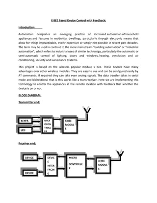
  • 1. X BEE Based Device Control with Feedback: Introduction: Automation designates an emerging practice of increased automation of household appliances and features in residential dwellings, particularly through electronic means that allow for things impracticable, overly expensive or simply not possible in recent past decades. The term may be used in contrast to the more mainstream "building automation" or “industrial automation”, which refers to industrial uses of similar technology, particularly the automatic or semi-automatic control of lighting, doors and windows, heating, ventilation and air conditioning, security and surveillance systems. This project is based on the wireless popular module x bee. These devices have many advantages over other wireless modules. They are easy to use and can be configured easily by AT commands. If required they can take even analog signals. The data transfer takes in serial mode and bidirectional that is this works like a transreceiver. Here we are implementing this technology to control the appliances at the remote location with feedback that whether the device is on or not. BLOCK DIAGRAM: Transmitter end: Receiver end: KEYPA MICR OCON TROLL ERLCD X BEE MODUL E MICRO CONTROLLE R DEVIC E INTER FACIN G DEVICE DEVICE X BEE MODUL E
  • 2. Blocks in brief: a) Transmitter Unit: Input unit: 1. Switch: This consists of the 4 switches for the control of the device Processing Unit 1. Controller Unit: This consists of the controller ATMEGA168 which is being programmed to take the input and generate the desired output. Output unit 1. X-bee module: This is basically transreceiver which will transmit the data wirelessly when from transmitter and will receive the data when sent from the receiver block. 2. LCD: This is a 16X2 B/W LCD used to display the data that is status of the devices. b) Receiver Unit: Input unit: 1. X-bee module: This is basically transreceiver which will transmit the data wirelessly when data is to be sent form this unit and will receive the data when sent from the transmitter block. Processing Unit 1. Controller Unit: This consists of the controller ATMEGA168 which is being programmed to take the input and generate the desired output. Output unit 1. RELAY Driver: IC ULN2803 will be used which can drive the relay proper voltage and current. 2. 4- Bit Relay Card: Automatic switch that will put on and off the devices. Note: The X-bee module is blank module. To make it function we have to configure the module that is as coordinator and router then it functions. For this AT commands are being sent to the X-bee module. There is much software to configure the X-bee available.
  • 3. Working: With the help of following block diagram we can easily describe the project. Two microcontrollers are required to control the two x bee modules. Using buttons on the transmitter end we can on- off any device connected at the receiver end. The LCD will display the current status of the devices. At any time we can check the status of the devices. Components Used: Hardware Components: 1. X BEE modules 2. LM117 Voltage regulator 3. Switch 4. Microcontrollers 5. LCD 6. Relay 7. ULN2803 8. Power supply block  X BEE: X Bee is the standards-based wireless technology designed to address the unique needs of low-cost, low-power wireless sensor and control networks in just about any market. ZigBee can be used almost anywhere, is easy to implement and needs little power to operate. With hundreds of members around the globe, ZigBee uses the 2.4 GHz radio frequency to deliver a variety of reliable and easy-to-use standards anywhere in the world. ZigBee is a specification for a suite of high level communication protocols using small, low-power digital radios based on the IEEE 802.15.4-2003 standard for wireless home area networks (WHANs), such as wireless light switches with lamps, electrical meters with in-home- displays, consumer electronics equipment via short-range radio. The technology defined by the ZigBee specification is intended to be simpler and less ex pensive than other WPANs, such as
  • 4. Bluetooth. ZigBee is targeted at radio-frequency (RF) applications that require a low data rate, long battery life, and secure networking. This is basically a transreceiver module.  ATMEGA 168/328: The Atmel AVR core combines a rich instruction set with 32 general purpose working registers. All the 32 registers are directly connected to the Arithmetic Logic Unit (ALU), allowing two independent registers to be accessed in one single instruction executed in one clock cycle. The resulting architecture is more code efficient while achieving throughputs up to ten times faster than conventional CISC microcontrollers. The Atmega168 provides the following features: 16 Kbytes of In-System Programmable Flash with Read-While-Write capabilities, 512 bytes of EEPROM, 1 Kbyte of SRAM, 23 general purpose I/O lines, 32 general purpose working registers, three flexible Timer/Counters with compare modes, internal and external interrupts, a serial programmable USART, a byte oriented Two wire Serial Interface, a 6-channel ADC (eight channels in TQFP and QFN/MLF packages) with 10-bit accuracy, a programmable Watchdog Timer with Internal Oscillator, an SPI serial port, and five software selectable power saving modes. The Idle mode stops the CPU while allowing the SRAM; Timer/Counters, SPI port, and interrupt system to continue functioning. The Power down mode saves the register contents but freezes the Oscillator, disabling all other chip functions until the next Interrupt or Hardware Reset. In Power-save mode, the asynchronous timer continues to run, allowing the user to maintain a timer base while the rest of the device is sleeping. The ADC Noise Reduction mode stops the CPU and all I/O modules except asynchronous timer and ADC, to minimize switching noise during ADC conversions. In Standby mode, the crystal/resonator Oscillator is running while the rest of the device is sleeping. This allows very fast start-up combined with low-power consumption.
  • 5.  Liquid Crystal Display: This is 16x2 B/W LCD for the display of the data.  Relay Driver: ULN2803 is a current driver IC which drives the relay. The eight NPN Darlington connected transistors in this family of arrays are ideally suited for interfacing between low logic level digital circuitry (such as TTL, CMOS or PMOS/NMOS) and the higher current/voltage requirements of lamps, relays, printer hammers or other similar loads for a broad range of computer, industrial, and consumer applications. All devices feature open–collector outputs and freewheeling clamp diodes for transient Suppression. The ULN2803 is designed to be compatible with standard TTL families while the ULN2804 is optimized for 6 to 15 volt high level CMOS or PMOS.  RELAY: A relay is an electrically operated switch. Many relays use an electromagnet to operate a switching mechanism mechanically, but other operating principles are also used. Relays are used where it is necessary to control a circuit by a low-power signal (with complete electrical isolation between control and controlled circuits), or where several circuits must be controlled by one sign. Here, relay is used to switch on the devices.  LM117: This is special voltage regulator which gives 3.3 V as output used for the X-bee power supply.
  • 6.  Switches: The switches are simple micro-switch that mini push to on switch that makes the point continuous while pressed and discontinuous when released.  Power Supply Block: The power supply consists of a step down transformer 230/12V, which steps down the voltage to 12V AC. This is converted to DC using a Bridge rectifier. The ripples are removed using a capacitive filter and it is then regulated to +5V using a voltage regulator 7805 which is required for the operation of the microcontroller and other components. Note: Transmitter unit is battery powered SOFTWARE COMPONENT: ARDUINO COMPILER: The Arduino IDE is a cross-platform application written in Java, and is derived from the IDE for the Processing programming language and the Wiring project. It is designed to introduce programming to artists and other newcomers unfamiliar with software development. It includes a code editor with features such as syntax highlighting, brace matching, and automatic indentation, and is also capable of compiling and uploading programs to the board with a single click. There is typically no need to edit make files or run programs on a command- line interface. Although building on command-line is possible if required with some third-party tools such as Ino. The Arduino IDE comes with a C/C++ library called "Wiring" (from the project of the same name), which makes many common input/output operations much easier. Arduino programs are written in C/C++. Advantages and applications:  The primary advantage is that the X-Bee modules are ‘bi- directional’. Most budget 433 systems only transmit in one direction, so the transmitter has no idea whether the
  • 7. receiver is actually getting the data! The X-Bee modules transmit and receive in both directions, so you can easily test (at both ends) if the system is working correctly.  The second advantage is that of unique addressing. Each X-Bee unit has a unique serial number. This means two (or more) units can be set up to exclusively talk to each other, ignoring all signals from other modules. This is not easily achieved with 433 modules.  The third advantage is that the X-Bee module has in build ‘data-packet’ building and error-checking to ensure reliable data transmission.  Finally the X-Bee protocol allows for a number of ‘channels’. By setting different units on different c0hannels additional interference can be avoided.  X-bee can used to sort out any type of wireless applications in limited range like physical parameter monitoring, PC to PC communication without net, develop LAN network without internet, wireless control applications etc.