The document describes the architecture of an 8051 microcontroller. It contains the following key components: CPU, ROM, RAM, timers, I/O ports, serial port and interrupt sources. The microcontroller has all these components integrated on a single chip. It has fixed amounts of on-chip ROM, RAM and I/O ports. Microcontrollers are used in applications where cost, power and space are critical as compared to microprocessors which have external memory and I/O devices.
Ei502microprocessorsmicrtocontrollerspart4 8051 MicrocontrollerDebasis Das
The document discusses the applications and features of microcontrollers. It provides examples of using microcontrollers for interfacing seven segment displays, temperature control, and other applications. It also discusses where microcontrollers can commonly be found, such as in cell phones, laptops, appliances, toys and more. The document outlines reasons for learning about microprocessors/controllers and provides an overview of the 8051 microcontroller, including its architecture, pins, registers and memory mapping.
The document discusses programming the 8051 microcontroller. It can be programmed using low-level assembly language or high-level languages like C. Assembly language code is faster but more difficult to write and less portable, while C code is easier but slower. The document provides examples of adding two numbers in both C and assembly. It also discusses the 8051 instruction set, addressing modes, subroutines, and arithmetic operations.
This presentation discusses the internal architecture of Intel 8051. It discusses basic families of 8051, the programmer view, register sets and memory organiszation of 8051
The document describes the architecture and instruction set of the 8051 microcontroller. It includes details about the memory map, internal data memory organization, special function registers, addressing modes, and common instructions. The 8051 has 4KB of on-chip ROM, 128 bytes of internal RAM, 21 special function registers, and supports operations on bytes, bits, and 16-bit data using various addressing modes like register, direct, indirect, and immediate addressing. Instructions allow data transfer, arithmetic, logic, and program control operations.
The 8051 microcontroller combines the CPU, RAM, ROM, I/O ports, and timers onto a single chip. It was introduced by Intel in 1981 as an 8-bit microcontroller called the 8051. The 8051 has 4KB of program memory, 128 bytes of RAM, 32 I/O lines, and two timers. It helped popularize embedded systems by providing these components in a single package with low power consumption.
The 8051 microcontroller is an 8-bit microcontroller commonly used in embedded systems. It has 8KB of ROM, 128 bytes of RAM, four I/O ports, two timers, and supports interrupts. It uses a 12MHz crystal oscillator as its system clock. The CPU fetches and executes instructions from code memory and accesses data memory through an internal address/data bus. It has various special function registers for control and status. Ports are bi-directional and can be configured for input or output through writing/reading values.
This document provides an overview of microcontrollers and the 8051 microcontroller. It discusses the basic components of microprocessors and microcontrollers, compares microprocessors and microcontrollers, lists common applications of microcontrollers in embedded systems, and criteria for choosing a microcontroller. It then focuses on the features, pin descriptions and functions, and CPU operation of the 8051 microcontroller.
The document discusses an agenda for a session on the 8051 microcontroller. It includes introductions to the 8051 microcontroller, its characteristics, pin diagram, programming languages including assembly and C, software used, and interfacing examples like LEDs, 7-segment displays, and LCDs. It also describes a project to interface a digital clock with a visitor counter.
The Microcontroller 8051 Family
Features of 8051 Microcontroller
Pin Configuration of 8051 Microcontroller
Ports of 8051 Microcontroller
Architecture of 8051 Microcontroller
Registers of 8051
Special Function Registers (SFR's)
Bit addressable RAM
Register Bank and Stack of 8051
The 8051 microcontroller has 4K bytes of internal ROM, 128 bytes of internal RAM, four 8-bit I/O ports, two 16-bit timers/counters, and one serial interface. It uses a Harvard architecture with separate memory spaces for program and data. External memory can be used for both program and data via address multiplexing. The machine cycle time depends on the oscillator frequency, with examples given of 1.085 μs for an 11.0592 MHz oscillator and 0.75 μs for a 16 MHz oscillator.
The document discusses the instruction set of the 8051 microcontroller. It describes different types of instructions such as arithmetic, data transfer, logical, branching, and bitwise logical instructions. It provides examples of instructions like ADD, MOV, INC, ANL, CLR, and CPL. It also shows the effect of sample instructions on registers and flags before and after execution.
The 8051 architecture contains an accumulator, program status word, stack pointer, data pointer, ports 0-3, serial data buffer, timer registers, control registers, timing and control unit, oscillator, instruction register, program address register, RAM, RAM address register, ALU, and SFR register bank. The accumulator is used to store operands. The program status word contains status flags. The stack pointer increments before data is pushed onto or called from the stack. The data pointer is a 16-bit register used to address external RAM. Each I/O port has a latch and driver. The serial data buffer contains transmit and receive registers. Timer and control registers control interrupts, timers, counters, and the serial port. The
The document discusses the 8051 microcontroller. It begins with an introduction and table of contents. It then provides details about the 8051 including its block diagram, pin descriptions and functions, memory mapping, registers, stack, I/O port programming, timers, and interrupts.
This document discusses serial communication using the 8051 microcontroller. It begins by introducing serial vs parallel data transfer, communication modes, and framing. It then describes the RS-232 protocol and pinout when using the 8051 UART. Setting the baud rate using Timer 1 is explained. The document provides details on the Serial Control Register and transmitting and receiving data with the serial port. It concludes by discussing using interrupts with the serial port and providing an example of transmitting data from Port 1 and receiving to Port 0 using interrupts.
The document discusses the 8051 microcontroller. It provides three key criteria for choosing a microcontroller: 1) meeting computing needs efficiently and cost effectively, 2) availability of software development tools, and 3) reliable sources. It then describes the basic components and features of the 8051, including 4K bytes of ROM, 128 bytes of RAM, four 8-bit I/O ports, two timers/counters, a serial interface, and support for external memory. Finally, it explains the memory organization and allocation of the 8051, distinguishing program memory, data memory, and external RAM.
The document summarizes the registers of the 8051 microcontroller. It describes the four register banks that each contain registers R0-R7. It also describes the special function registers for tasks like timers, serial ports, and analog-to-digital conversion that are located from addresses 80h-FFh. Some key 16-bit and 8-bit registers are the accumulator, program status word, stack pointer, program counter, and data pointer. The program status word contains registers for interrupt enable, interrupt priority, and timer/counter control.
The document discusses various jump, loop, and call instructions for the 8051 microcontroller. It provides examples of using conditional and unconditional jumps to transfer program flow. Looping is achieved using decrement and jump if not zero instructions. Nested loops allow repeating an action more than 256 times. Subroutines are called using call instructions which save the return address on the stack. Parameters can be passed into subroutines using registers or push/pop instructions.
The document discusses various topics related to interfacing an 8051 microcontroller, including:
1. Serial communication between an 8051 and PC using RS-232 and a MAX232 chip.
2. Half-duplex and asynchronous serial communication modes.
3. Addressing modes of the 8051 including register, direct, indirect, and indexed addressing.
4. Instructions sets, registers, and programming of the 8051 microcontroller.
This slides includes all the necessary steps to Program 8051 family micro-controller. A fresher will be able to simulate LCD in Proteus Using C in Keil !!
The Program Status Word (PSW) is an 8-bit register that contains status flags in microprocessors like the 8085 and microcontrollers like the 8051. The PSW has an accumulator and flag register, with the accumulator being higher order and flag register lower order. The PSW tracks status flags like the carry, parity, auxiliary, zero, and sign flags to indicate results of operations such as carries/borrows between bits and whether a result is zero or negative.
The document discusses the 8051 microcontroller. It describes the basic components of the 8051 including 4K bytes of internal ROM, 128 bytes of internal RAM, four 8-bit I/O ports, two 16-bit timers/counters, and one serial interface. It also provides details on the block diagram, important pins like ports and serial interface pins, and how to connect an external clock source to the 8051.
The document provides an introduction to 8051 assembly language programming. It discusses that CPUs can only work with binary but programming in 0s and 1s is tedious for humans. Assembly language was developed to provide mnemonics for machine code instructions and make programming faster and less error prone. It also summarizes key aspects of 8051 architecture like registers, memory allocation, timers and counters.
An embedded system is closely integrated with the main system
It may not interact directly with the environment
For example – A microcomputer in a car ignition control
This document discusses various applications of embedded systems including temperature measurement using thermistors and linear temperature sensors like the LM35. It describes how to interface the LM35 temperature sensor with an 8-bit ADC0809 and microcontroller port for temperature readings. It also discusses controlling a stepper motor and interfacing it to port pins of a microcontroller. Finally, it explains interfacing a 2x16 LCD display and keyboard matrix to a microcontroller for input/output applications.
The document discusses the 8051 microcontroller. It begins by explaining why we need to learn about microprocessors and microcontrollers, noting that many modern devices are controlled by them. It then covers the basic components of a microprocessor/controller including the CPU, I/O, memory, timers, and interrupts. The rest of the document provides details on the 8051 microcontroller, including its architecture, memory structure, registers, ports and other features. It compares microprocessors and microcontrollers, and discusses how to choose between different microcontroller options for embedded systems.
El documento describe los primeros meses de vida de una bebé, desde su nacimiento hasta su primer cumplemes, mostrando fotos de ella con sus padres, abuelos y primos disfrutando de momentos especiales como su llegada a casa, paseos en coche, tiempo en brazos de su padre y celebraciones como su primer cumpleaños.
The document discusses the human circulatory system and cell metabolism. It describes how blood flows from the heart through arteries and capillaries, then returns to the heart through veins. The circulatory system transports blood to tissues and cells to exchange oxygen, nutrients, and waste. Cell metabolism allows cells to convert food into energy through chemical reactions.
This document provides information on switching from automatic to manual modes on a camera. It describes the characteristics and uses of different exposure modes including Program, Shutter Priority, Aperture Priority, and Manual. It also covers different scene modes like Portrait, Landscape, Macro, Sports, and Night Portrait. The exposure triangle of aperture, shutter speed, and ISO is explained. Concepts of over and underexposure, depth of field, freezing versus blurring motion, and the relationship between ISO and image quality are discussed. Activities are suggested to understand these photographic concepts hands-on.
This document provides instructions for analyzing 10 photos by identifying the subject, nature, location, lighting, and focus for each photo, then using knowledge of aperture, shutter speed, and ISO to determine how each photo was captured.
The Glorious Revolution occurred in 1688 when the English Parliament invited William III of Orange-Nassau to overthrow King James II and become co-ruler with his wife Mary II. This established constitutional monarchy and secured a Protestant line of succession. As a result, Parliament passed the Bill of Rights in 1689 which limited royal power and established rights for citizens, and the Act of Settlement in 1701 which prevented Catholics from inheriting the throne. The Revolution had lasting effects on religion, finance, and freedom of the press in England.
The document describes a Git multi-repository workflow that allows each team to work independently in their own Git repository while also sharing a central "root" repository. Key aspects include each team having their own repository, a master root repository, and continuous integration (CI) being used to merge changes between repositories and ensure stability on chosen branches.
Best software development team refreshed4slideshareJulien Plée
To be the best development team, focus on solving problems regularly by being agile, adding value, and giving back. Maintain quality through techniques like QA pairing and continuous learning and progress. Stay focused on customer and developer satisfaction.
The Battle of Huai Hai was a decisive battle in the Chinese Civil War that resulted in Communist control over China. Using guerilla tactics like ambushes and sabotage, the Communists took control of much of northern and central China. At the Battle of Huai Hai, the Communists employed a three-stage strategy to defeat the Nationalists, destroying two armies totaling over 200,000 troops. This major defeat crippled the GMD and allowed the Communists to quickly take control of key cities and eventually establish the People's Republic of China.
The document discusses the Chinese Civil War between the Communist Party of China (CCP) and the nationalist Kuomintang (GMD) from 1946-1949. It examines their differing aims and policies. The CCP aimed to empower peasants by reducing rents and taxes, banning outdated practices, and establishing women's groups. They gained widespread rural support. In contrast, the GMD struggled with inflation, worker strikes, and unrest in the cities they controlled. Ultimately, the CCP's shift to conventional warfare tactics in their "Strong Point Offensive" allowed them to defeat the GMD and take control of China by 1949.
Here is a possible 10 mark response using the source and own knowledge:
The Nazi Party announced its 25 point programme in 1920 which set out its nationalist and anti-Semitic policies. This helped gain some early support. However, Hitler's tactics were too extreme at this stage. In 1921 he set up the SA or Brownshirts as a private army to use violence and intimidation against political opponents. This foreshadowed the militant tactics that would later help the Nazis rise to power.
The Munich Putsch in 1923 where Hitler tried to seize power by force was a failure and led to his arrest. This event marked an important change in Hitler's approach. After being released from prison in 1924/25, Hitler realised he needed to use
This document provides an overview of a lesson on civil rights in the 1950s for Black Americans. It includes key terms, events, and names related to the history of Black Americans from slavery through 1945. It outlines assignments for students to create a timeline of important turning points in progress toward equality, including taking a short test to ensure understanding of the events. It also includes content on segregation, discrimination, and the position of Black Americans before 1945.
This document provides guidance on the pre-production and production steps for creating an engaging documentary. It recommends researching the topic thoroughly, writing a treatment and script, storyboarding scenes, getting feedback, and preparing for challenges. Key pre-production steps include watching other documentaries for style inspiration, prioritizing scenes, and drawing a storyboard. Production involves collecting b-roll footage, choosing appropriate locations, ensuring good audio quality, and properly interviewing subjects by making them comfortable and planning focused questions.
Martin Luther King Jr.'s assassination in 1968 had major consequences for the civil rights movement in the United States. As the most prominent leader and spokesperson, his death left the movement without its figurehead and main organizer at a pivotal time. It also sparked riots across many US cities and damaged the image of the civil rights movement. The momentum of the movement declined as support for it waned in the aftermath. The failure of Resurrection City, set up to continue King's Poor People's Campaign, further weakened the movement and its ability to stage large demonstrations. By the late 1960s, the civil rights movement had lost much of its prominence as the focus shifted to opposing the Vietnam War.
The document discusses the formation and structure of the Weimar Republic in Germany following World War 1. It explains that the Social Democratic Party established a new democratic government called the Weimar Republic after Kaiser Wilhelm abdicated. The Weimar Constitution established democratic principles like universal suffrage, separation of powers, and civil liberties. However, it also had weaknesses like proportional representation making it difficult to form stable governments, and the president's ability to rule by decree which undermined the legislature.
A photographic essay tells a story or evokes emotions through a series of photographs. It can convey more than a single image. Photographic essays can be purely photographic or can include captions or text. They can have a narrative structure and tell a story chronologically, or they can have a thematic structure and address a particular topic or issue. Effective photographic essays consider themes, subjects, structures, and techniques to craft a coherent narrative and evoke specific emotions in the viewer.
The document discusses the causes and growth of the Red Scare in the United States after World War 2. Key events that contributed to rising anti-communist fear and paranoia included the spread of communism in Europe, the Soviet development of nuclear weapons, China falling to communism, and the start of the Korean War. Within the US, investigations by the House Un-American Activities Committee and Federal Bureau of Investigation targeted suspected communists, especially in Hollywood and the federal government. This led to blacklists and prosecutions like the Hollywood Ten and Alger Hiss case, fueling further anti-communist hysteria and laws restricting civil liberties.
The document provides an overview of the 8051 microcontroller, including its block diagram, pin descriptions, registers, memory mapping, stack, timers, and interrupts. It describes the CPU, RAM, ROM, I/O ports, timers, and interrupt control that are integrated into a single chip in the 8051 microcontroller. It also explains various registers related to timers and interrupts in the 8051.
Presentation On: "Micro-controller 8051 & Embedded System"surabhii007
The presentation is dealing with majors about 'An Embedded System' along with 'Micro-controller' with it's base peripherals & parameters.
Hope It'll be helpfull!
The document discusses the Microcontroller 8051. It provides a block diagram and pin description of the 8051. It describes the registers, memory mapping, stack, I/O ports, timers and interrupts of the 8051 microcontroller. It compares microprocessors and microcontrollers, discussing the differences in hardware structure and applications.
This document provides an overview of the 8051 microcontroller architecture. It describes the basic components of the 8051 including 4K bytes of internal ROM, 128 bytes of internal RAM, four 8-bit I/O ports, two timers/counters, one serial interface, and other features. It also discusses the different addressing modes for 8051 assembly language programming including immediate, register, direct, register indirect, and external direct addressing.
This document provides an overview of memory and registers in the 8051 microcontroller. It discusses the on-chip ROM and RAM memory, as well as the various registers including the 8-bit registers (A, B, R0-R7) and 16-bit registers (DPTR, PC). It also covers the register banks and stack area in RAM, as well as data types and directives like DB and EQU that can be used to define data. Finally, it discusses addressing modes and instruction formats for the 8051 assembly language.
The document describes the architecture and components of an 8051 microcontroller. It includes details about the CPU registers like the accumulator, program status word, stack pointer, and timers. It describes the ports, interrupts, and memory organization. The special function registers control functions like timers, serial communication, and interrupts. The timers can be configured in different modes to generate time delays or count events. External memory can be accessed using address and data lines connected to the ports.
The document describes the architecture and components of an 8051 microcontroller. It contains:
- An 8-bit CPU with registers A and B, 4KB internal ROM, 16-bit program counter and data pointer, 128 bytes of RAM, and an 8-bit program status word.
- Two 16-bit counters/timers, four 8-bit I/O ports, and interrupts.
- Registers including accumulator, B register, program status word, stack pointer, and data pointer.
- Timers, serial I/O, and I/O ports for input/output.
The document discusses different aspects of microprocessors and microcontrollers including hardware, software, common components like CPU, memory, I/O ports, and differences between microprocessors and microcontrollers. It provides block diagrams of a general microprocessor system and microcontroller with descriptions of each component. Examples given include the Intel 8051 microcontroller and its pin descriptions and registers.
An embedded system is a special-purpose computer system designed to perform one or a few dedicated functions, often with real-time computing constraints. Embedded systems are present in many devices such as household appliances, vehicles, medical equipment, smartphones, and more. They typically use microcontrollers or microprocessors to monitor and control embedded hardware components. Key components of embedded systems include a CPU, memory, I/O ports, and timers/counters. Microcontrollers integrate most of these components onto a single chip, while microprocessors require external components. Embedded systems use various addressing modes and have inputs like interrupts and timers that allow them to interact with the external environment. Common applications areas of embedded systems include consumer electronics, industrial automation, automotive systems,
The document provides an overview of the Silicon Labs C8051F020 microcontroller. It describes the microcontroller's CPU, memory organization, I/O ports, analog and digital peripherals such as ADCs, DACs, and comparators. It also discusses the microcontroller's special function registers used to control and interface with its various peripherals.
This document provides information about the features and architecture of the 8051 microcontroller. It describes the 8-bit CPU, 64K program memory, 64K data memory, 4K on-chip program memory, 128 bytes of on-chip data RAM, 32 I/O lines, two timers, UART serial communication, interrupt structure, and on-chip oscillator. It also covers the pin descriptions, registers, memory mapping, stack, I/O port programming, timers, and interrupts of the 8051. Finally, it discusses the instruction set groups for arithmetic, logical, data transfer, boolean, and program branching operations.
The document discusses embedded systems and microcontrollers. It provides details about the 8051 and 8085 microcontrollers, including their architecture, pins, applications, addressing modes, and interrupts. The 8051 has features like 4KB ROM, 128B RAM, timers, serial port, I/O ports. Common applications include digital clocks and traffic lights. It uses addressing modes like immediate, register indirect, and direct. The 8085 is an 8-bit microprocessor with multiplexed address/data bus and works on a 5V supply.
This document discusses an embedded systems presentation submitted by Amandeep Singh. It provides definitions and examples of embedded systems, noting they are designed for specific applications like industrial machines, medical equipment, and toys. It also summarizes key aspects of embedded system components like microcontrollers, addressing modes, and applications. Recent examples highlighted are devices that aid communication for the deaf, integrate weighing and dimension measuring, and allow adjustable cushioning in smart shoes.
This document discusses the architecture and programming of the 8051 microcontroller. It begins by outlining the objectives and outcomes of studying the 8051. It then provides details on the basics of the 8051 architecture, including its internal blocks like RAM, registers, timers, ports, and memory organization. It also compares microcontrollers to general purpose microprocessors. Finally, it discusses the internal registers of the 8051 like the program counter, stack pointer, and special function registers in detail.
Technology is constantly changing. New microcontrollers become available every year. The one thing that has stayed the same is the C programming language used to program these microcontrollers. If you would like to learn this standard language to program microcontrollers, then this book is for you!
Arduino is the hardware platform used to teach the C programming language as Arduino boards are available worldwide and contain the popular AVR microcontrollers from Atmel.
The document provides information about the 8051 microcontroller. It describes the basic components of a microcontroller including the CPU, memory, I/O ports, and timers. It explains the pin layout and functions of the 8051 microcontroller. Key components like registers, memory mapping, stack, and interrupts of the 8051 are summarized. Programming I/O ports and timers is also covered at a high level.
The document describes the 8085 microprocessor, including its pin diagram, functional units, architecture, and example assembly language programs. Specifically, it provides details on the 8085's power supply and frequency pins, data and address buses, control signals, interrupt signals, and serial and DMA signals. It outlines the 8085's functional units like the accumulator, arithmetic logic unit, registers, and timing and control unit. Example programs are provided to exchange 16-bit numbers, add and subtract 8-bit and 16-bit numbers, and add two N-byte numbers.
The AT89C52 is a low-power microcontroller with 8K bytes of flash memory. It has 8 I/O lines, 3 timers/counters, a serial port, and supports two power saving modes. The document describes the features of the microcontroller including memory, I/O ports, pins, and special function registers. It provides detailed information on the functions of various pins and registers for timers, interrupts, and other peripherals.
Gender and Mental Health - Counselling and Family Therapy Applications and In...PsychoTech Services
A proprietary approach developed by bringing together the best of learning theories from Psychology, design principles from the world of visualization, and pedagogical methods from over a decade of training experience, that enables you to: Learn better, faster!
This presentation was provided by Rebecca Benner, Ph.D., of the American Society of Anesthesiologists, for the second session of NISO's 2024 Training Series "DEIA in the Scholarly Landscape." Session Two: 'Expanding Pathways to Publishing Careers,' was held June 13, 2024.
A Visual Guide to 1 Samuel | A Tale of Two HeartsSteve Thomason
These slides walk through the story of 1 Samuel. Samuel is the last judge of Israel. The people reject God and want a king. Saul is anointed as the first king, but he is not a good king. David, the shepherd boy is anointed and Saul is envious of him. David shows honor while Saul continues to self destruct.
How to Setup Warehouse & Location in Odoo 17 InventoryCeline George
In this slide, we'll explore how to set up warehouses and locations in Odoo 17 Inventory. This will help us manage our stock effectively, track inventory levels, and streamline warehouse operations.
The chapter Lifelines of National Economy in Class 10 Geography focuses on the various modes of transportation and communication that play a vital role in the economic development of a country. These lifelines are crucial for the movement of goods, services, and people, thereby connecting different regions and promoting economic activities.
Level 3 NCEA - NZ: A Nation In the Making 1872 - 1900 SML.pptHenry Hollis
The History of NZ 1870-1900.
Making of a Nation.
From the NZ Wars to Liberals,
Richard Seddon, George Grey,
Social Laboratory, New Zealand,
Confiscations, Kotahitanga, Kingitanga, Parliament, Suffrage, Repudiation, Economic Change, Agriculture, Gold Mining, Timber, Flax, Sheep, Dairying,
ISO/IEC 27001, ISO/IEC 42001, and GDPR: Best Practices for Implementation and...PECB
Denis is a dynamic and results-driven Chief Information Officer (CIO) with a distinguished career spanning information systems analysis and technical project management. With a proven track record of spearheading the design and delivery of cutting-edge Information Management solutions, he has consistently elevated business operations, streamlined reporting functions, and maximized process efficiency.
Certified as an ISO/IEC 27001: Information Security Management Systems (ISMS) Lead Implementer, Data Protection Officer, and Cyber Risks Analyst, Denis brings a heightened focus on data security, privacy, and cyber resilience to every endeavor.
His expertise extends across a diverse spectrum of reporting, database, and web development applications, underpinned by an exceptional grasp of data storage and virtualization technologies. His proficiency in application testing, database administration, and data cleansing ensures seamless execution of complex projects.
What sets Denis apart is his comprehensive understanding of Business and Systems Analysis technologies, honed through involvement in all phases of the Software Development Lifecycle (SDLC). From meticulous requirements gathering to precise analysis, innovative design, rigorous development, thorough testing, and successful implementation, he has consistently delivered exceptional results.
Throughout his career, he has taken on multifaceted roles, from leading technical project management teams to owning solutions that drive operational excellence. His conscientious and proactive approach is unwavering, whether he is working independently or collaboratively within a team. His ability to connect with colleagues on a personal level underscores his commitment to fostering a harmonious and productive workplace environment.
Date: May 29, 2024
Tags: Information Security, ISO/IEC 27001, ISO/IEC 42001, Artificial Intelligence, GDPR
-------------------------------------------------------------------------------
Find out more about ISO training and certification services
Training: ISO/IEC 27001 Information Security Management System - EN | PECB
ISO/IEC 42001 Artificial Intelligence Management System - EN | PECB
General Data Protection Regulation (GDPR) - Training Courses - EN | PECB
Webinars: https://pecb.com/webinars
Article: https://pecb.com/article
-------------------------------------------------------------------------------
For more information about PECB:
Website: https://pecb.com/
LinkedIn: https://www.linkedin.com/company/pecb/
Facebook: https://www.facebook.com/PECBInternational/
Slideshare: http://www.slideshare.net/PECBCERTIFICATION
3. Microprocessor :
•CPU is stand-alone, RAM, ROM, I/O, timer are separate
•Designer can decide on the amount of ROM, RAM and I/O ports.
•Expensive
•Versatility
•General-purpose
Microcontroller:
•CPU, RAM, ROM, I/O and timer are all on a single chip
•Fix amount of on-chip ROM, RAM, I/O ports
•For applications in which cost, power and space are critical
•Single-purpose
4.
5. Overview of 8051 family
8051 is a 8-bit micro controller ,it is introduced by
Intel corporation.8051 is the original member of the 8051 family.
Other members of 8051 family
8052 and 8031 are the other family members of 8051.
The following table gives comparison of 8051 family members
Feature
8051
8052
8031
ROM(on-chip program space in bytes)
4K
8K
0K
RAM(bytes)
128
256
128
Timers
2
3
2
1/O pins
32
32
32
Serial Port
1
1
1
Interrupt sources
6
8
6
6. Various 8051 microcontrollers
8051 is available in different memory types,such as UV-EPROM ,
flash,and NV-RAM,all of which have different memory types.
AT89C51 from Atmel corporation:
This 8051 chip has on-chip ROM in the form of flash memory.
AT89C51 is used in place of the 8751 to eliminate the waiting
time needed to erase the chip and thereby speed up the
development time.
7. DS from Dallas Semiconductor
DS5000 is another chip from Dallas semiconductor.The onchip ROM for the DS5000 is in the form of NV-RAM.The
read/write capability of NV-RAM allows the program to be
loaded into the on-chip ROM while it is in the system.
1.Having on-chip back up battery
2.Having special circuit which connects RAM to battery
immediately after removing the supply voltage
8. P89C51RD2BN from Phillips:
It is another major producer of 8051 family from Phillips
Corporation
It has the following features
1.It has 64K bytes of on-chip ROM
2.Allows In system programming (ISP).Hence no need to use
PROM programmer
10. Pin number
Description
Vcc(Pin 40)
Provides supply voltage to the chip .The voltage
source is +5V
GND(Pin 20)
It is the Ground
XTAL1(Pin19)
and
XTAL2(Pin18)
The 8051 needs external clock to run it.Most often
quartz crystal oscillator is connected to inputs
XTAL1(Pin 19) and XTAL(Pin 18)
RST(Pin 9)
It is the RESET pin.Upon applying high pulse to
this pin the micro controller will reset and terminate
all activities
EA (Pin 31)
The 8051 family members all come with on-chip
ROM to store programs.So EA connected to Vcc.
PSEN (Pin 29)
This is an output pin .PSEN stands for “Program
store enable”
ALE (Pin 30)
ALE(address latch enable) is an output pin and is
active high.This is used for demultiplexing the
address and data by connecting to the G pin of
74LS373 chip
11. Interfacing External program memory
P1
Instruction
P0
EA
ALE
P3
1
Address
Latch
P2
OE
PSEN
0
Microcontroller
External ROM
12. Interfacing External data memory
P1
Data
P0
EA
Vcc
ALE
1
P3
Latch
Address
P2
RD
WR
Microcontroller
I/O
Page bits
WE
OE
0
External data memory
13.
14. CPU can work only in binary,it can do so at a very high
speed ,but its slow and tedious for humans to deal with 0’s
and 1’s I.e with machine language.
Assembly language were developed which provided
mnemonics for the machine code instructions, plus other
features which made programming faster and less prone to
error.
Assembler is a program which converts assembly
language into machine level language
Assembly language is referred to as a low level language
because it deals directly with the internal structure of the
CPU
High level languages are translated into machine code by
a program called a complier
15. - In the CPU ,registers are used to store information temporarily.
- In 8051 there is only one data type : 8 bits.
D7
D6
D5
D4
D3
D2
Most significant bit
B
R0
D0
Least significant bit
Registers
A
D1
R1
R2
R3
R4
R5
R6
R7
8- bit Registers of the 8051
DPTR
PC
DPH
DPL
PC(Program counter)
16-bit register
16-bit register
16. An assembly language program consists of series of
assembly language instructions .
An assembly language instruction consists of a
mnemonic , optionally followed by one or more operands. The
operands are the data items being manipulated , and the
mnemonics are the commands to the CPU, telling it what to
do with those items.
Example:
ORG 00h
; start at location 0
MOV R5,#25h; load 25h into R5
MOV A, #0
;load 0 into A
ADD A,R5
;add contents of R5 to A
; now A =A +R5
END
; end of the asm source file
17. The following diagram shows steps to create an executable
assembly language program
Editor Program
Myfile.asm
Assembler Program
Myfile.lst
Other obj files
Myfile.obj
Linker Program
Myfile.abs
OH Program
Myfile.hex
18. Data Type
8051 micro controller has only one data type.It is of 8-bits,and
the size of each register is also 8 bits.
DB(Define byte)
DB directive is used to define data, the numbers can be in
decimal,binary,hex,or ASCII formats.
Examples:
DATA1: DB 28
;Decimal(1C in hex)
DATA2: DB 00110101B
;Binary (35 in hex)
DATA3: DB 39h
;hex
ORG 510H
DATA4: DB “My name is MIC “
;ASCII characters
19. Following are the more widely used directives of the 8051
ORG(origin)
The ORG directive is used to indicate the beginning of the address
ORG 025h
;starts at the 25th address
EQU(equate)
This is used to define a constant without occupying a memory
location.The EQU directive does not set aside storage for data item but
associates a constant value with a data label so that when the label
appears in the program,its constant value will be substituted for the label.
COUNT EQU 25
MOV R3 , #COUNT
;R3 becomes 25 here
END Directive
This indicates to the assembler the end of the source(asm) file.Anything
after the END directive is ignored by the assembler.
20. The flag register in the 8051 is called the Program Status
Word (PSW) register.It is used to indicate arithmetic conditions
such as a carry but.
PSW(Program status word) Register:
• The PSW register is an 8-bit register but only 6 bits of it are used
by the 8051 .
• The two unused bits are user-definable flags.
• Four of the flags are conditional flags meaning that they indicate
some conditions that resulted after an instruction was executed.
These are CY,AC,P,OV.
• The bits PSW.3 and PSW.4 are designated as RS0 and RS1 ,and are
used to change the bank registers.
• The PSW.5 and PSW.1 bits are general-purpose status flag bits and
can be used by the programmer for any purpose
21. CY
AC
F0
RS1
RS0
OV
----
P
CY
PSW.7
Carry flag
AC
PSW.6
Auxiliary carry flag
--
PSW.5
Available to the user for general purpose
RS1
PSW.4
Register bank selector bit 1
RS0
PSW.3
Register bank selector bit 0
OV
PSW.2
Overflow flag
--
PSW.1
User definable bit
P
PSW.0
Parity flag.Set/Cleared by hardware each
instruction cycle to indicate an odd/even
number of bits in the accumulator
23. Example: Show the status of the CY,AC and P flags after the
addition of 38H and 2Fh in the following instructions
MOV A,#38h
ADD A,#2FH
Solution:
38
00111000
+
2F
00101111
67
01100111
CY = 0 since there is no carry beyond D& bit
AC = 1 Since there is no carry from D3 to the D4 bit
P = 1 Since the accumulator has an odd number of 1’s
25. RAM Allocation in 8051
7F
Scratch pad RAM
30
2F
20
1F
Bit Addressable RAM
Register Bank 3
18
17
10
0F
Register Bank 2
Register Bank 1(stack)
08
07
00
Register Bank 0
27. Special function registers
99
98
9A
99
98
SBUF
SCON
9F 9E 9D 9C 9B
90
97
93 92
91
90
96
95
94
Not bit addressable
8B
Not bit addressable
8A
Not bit addressable
TH1
TH0
TL1
TLO
Not bit addressable
Not bit addressable
8F 8E 8D 8C 8B 8A
Not bit addressable
89
TMOD
88 TCON
PCON
82
Not bit addressable
DPH
DPL
81
Not bit addressable
SP
87
86
85
84
83
82
81
80
P0
E5
B8
-- -- --
B6
F3
F2
F1 F0
D3 D2 D1 D0
BC BB BA B9 B8
B5
B
E3 E2 E1 E0 ACC
E4
D0 D7 D6 D5 D4
B0 B7
Not bit addressable
80
F0 F7 F6 F5 F4
E0 E7 E6
8D
8C
89
88
87
84
FF
P1
Not bit addressable
B4
B2
B1
A8 AF -- -- AC AB AA A9
B0
PSW
IP
P3
A8 IE
A0 A7 A6 A5 A4 A3 A2 A1 A0 P2
29. POP 3
; POP stack into R3
POP 5
; POP stack into R5
POP 2
; POP stack into R2
After POP 3
0B
54
0A
F9
09
76
08
6C
Start SP
0B
0B
SP
09
76
6C
08
0A
76
09
0B
0B
F9
0A
08
6C
0A
After POP 2
After POP 5
0A
SP
09
08
09
6C
SP
08
Editor's Notes
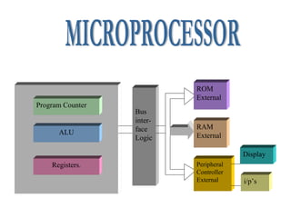
{"27":"Special function registers\n","22":"Example: \nShow the status of the CY,AC and P flags after the addition of 38H and 2Fh in the following instructions\nMOV A,#38h\nADD A,#2FH\nSolution:\n3800111000\n+2F00101111\n6701100111\nCY = 0 since there is no carry beyond D& bit\nAC = 1 Since there is no carry from D3 to the D4 bit\nP = 1 Since the accumulator has an odd number of 1’s\n","11":"External ROM\n","28":"Push operation on Stack\n","17":"Myfile.hex\n","12":"0\n","29":"POP 3;POP stack into R3\nPOP 5; POP stack into R576F954\nPOP 2;POP stack into R2\n","24":"InstructionCYOV AC\nADDXXX\nADDCXXX\nSUBBXXX\nMUL0X\nDIV0X\nDAX\nRRCX\nRLCX\nSETB C1\nCLR C0\nCPL CX\nANL C,bitX\nANL C,/bitX\nCJNEX\n","2":"Block diagram\n","25":"RAM Allocation in 8051\n","9":"8051\n(8031)\n","26":".\n","15":"16-bit register\n","21":"CYPSW.7Carry flag\nACPSW.6Auxiliary carry flag\n--PSW.5Available to the user for general purpose\nRS1PSW.4Register bank selector bit 1\nRS0PSW.3Register bank selector bit 0\nOVPSW.2Overflow flag\n--PSW.1User definable bit\nPPSW.0Parity flag.Set/Cleared by hardware each instruction cycle to indicate an odd/even number of bits in the accumulator\n"}