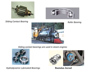
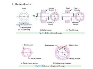
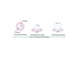
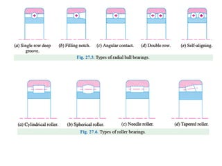
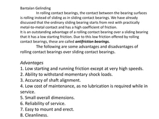
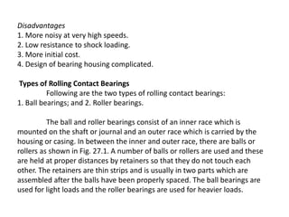
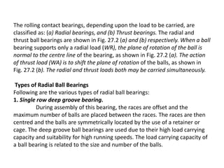
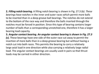
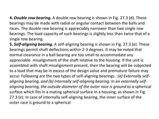
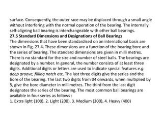
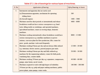
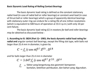
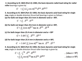
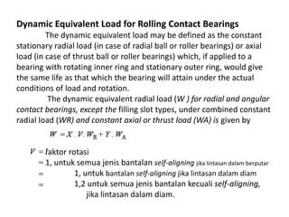
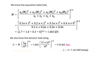
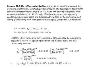
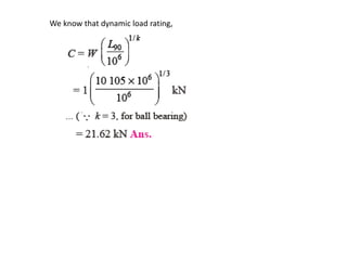
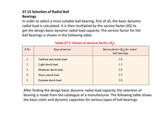
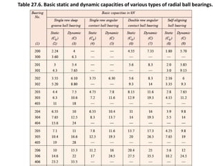
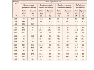
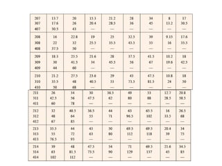
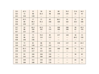
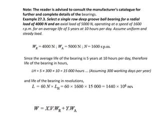
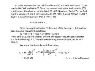
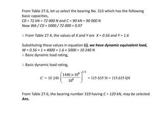
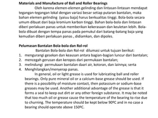
This document discusses different types of bearings used in mechanical systems. It describes sliding contact bearings and rolling contact bearings. Rolling contact bearings are further divided into ball bearings and roller bearings. The key advantages of rolling contact bearings over sliding contact bearings are their lower starting friction and operating friction, ability to withstand shock loads, and reliability. Radial bearings support radial loads while thrust bearings support axial loads. Common types of radial ball bearings are single row deep groove bearings and filling notch bearings.
Perbedaan Baja Karbon Rendah, Baja Karbon Menengah, dan Baja Karbon TinggiAbdul Ghofur
Salah satu cara mengklasifikasikan baja adalah berdasarkan pada komposisi kimianya. Kandungan karbon misalnya. Oleh karenanya kita mengenal penamaan Baja Karbon yang terbagi menjadi tiga jenis yakni Baja Karbon Rendah, Baja Karbon Menengah, dan Baja Karbon Tinggi. Dalam slide ini dijelaskan secara ringkas dan jelas agar dapat memahami perbedaan ketiga jenis baja karbon dengan baik.
MAchine Design and CAD Presentation. its topic is about Hydrodynamic Journal bearings, Heat Generated in a Journal Bearing
Design Procedure for Journal Bearing
And Examples
Spring is an elastic body whose function is to distort when loaded and to recover its original shape when the load is removed.
APPLICATION OF SPRINGS
To apply forces as in brakes, clutches and spring loaded valves.
To store energy as in watches, toys.
To measure forces as in spring balance and engine indicators.
To cushion, absorb or control energy due to either shock or vibration as in car.The material of the spring should have
high fatigue strength,
high ductility,
high resilience and
creep resistant.
It largely depends upon the size and service.
The strength of the wires varies with size, smaller size wires have greater strength and less ductility, due to the greater degree of cold working.
Severe service means rapid continuous loading where the ratio of minimum to maximum load (or stress) is one-half or less, as in automotive valve springs.
Average service includes the same stress range as in severe service but with only intermittent operation, as in engine governor springs and automobile suspension springs.
Light service includes springs subjected to loads that are static or very infrequently varied, as in safety valve springs.
The springs are mostly made from oil-tempered carbon steel wires containing 0.60 to 0.70 per cent carbon and 0.60 to 1.0 per cent manganese.
Design of sliding_contact_wearing_unitiiibalram yadav
A bearing is a machine element which support another moving machine element (known as journal). It permits a relative motion between the contact surfaces of the members, while carrying the load.
Rolling Contact Bearing, Selection of Rolling Contact Bearings, Machine Element Design, Bantalan Gelinding, Pemilihan Bantalan Gelinding, Perancangan Elemen Mesin
Design Optimization and Analysis of a Steam Turbine Rotor GroovesIOSR Journals
A large variety of turbo-machinery rotor groove geometries are used in industry. However, there is
no specific attempt made to compare them on the basis of performance. This paper provides an attempt to fill
that gap aiming to find an optimum geometry. The main objective of the investigations is to reduce fillet stress
concentration factor and associated deformations. The present work carries out the design modification of fillet
of a Steam Turbine Rotor. Finite Element Analysis is performed using ANSYS Workbench that is used to
determine the fillet stresses effectively to modify the blade rotor grooves. The low pressure steam turbine rotor
blades have usually a history of stress failure. They suffer from tensile and bending stresses partly due to the
centrifugal force as a result of high rotational speeds and partly due to high pressure, temperature and speed
steam loading. The centrifugal force is one of the problems that face the designers of turbine blades especially
the long ones. The designer always aims at reducing these stresses. One way to do so is by the reduction of
stress concentration factor which takes place between the rotor and its groove. That is to make the rotor blade
of variable cross section instead of straight. This paper presents the method of reducing stress concentration
factor as well as reduction in the deformation of the rotor
Keuntungan dan Kerugian Diesel Dibanding BensinCharis Muhammad
Motor bensin dan diesel adalah mesin pembakaran dalam yang banyak dipakai di dunia, ada beberapa keuntungan dan kerugian dari motor diesel dibandingkan dengan motor bensin.
Ada banyak sekali mesin pengubah (pengonversi) energi, salah satunya yaitu motor bensin yang mengubah eneergi kimia (bahan bakar) menjadi energi panas, diubah lagi menjadi energi gerak dan di konversi menjadi energi putar dan diteruskan oleh ban sehingga kendaraan dengan motor bensin bisa bergerak
Event Management System Vb Net Project Report.pdfKamal Acharya
In present era, the scopes of information technology growing with a very fast .We do not see any are untouched from this industry. The scope of information technology has become wider includes: Business and industry. Household Business, Communication, Education, Entertainment, Science, Medicine, Engineering, Distance Learning, Weather Forecasting. Carrier Searching and so on.
My project named “Event Management System” is software that store and maintained all events coordinated in college. It also helpful to print related reports. My project will help to record the events coordinated by faculties with their Name, Event subject, date & details in an efficient & effective ways.
In my system we have to make a system by which a user can record all events coordinated by a particular faculty. In our proposed system some more featured are added which differs it from the existing system such as security.
About
Indigenized remote control interface card suitable for MAFI system CCR equipment. Compatible for IDM8000 CCR. Backplane mounted serial and TCP/Ethernet communication module for CCR remote access. IDM 8000 CCR remote control on serial and TCP protocol.
• Remote control: Parallel or serial interface.
• Compatible with MAFI CCR system.
• Compatible with IDM8000 CCR.
• Compatible with Backplane mount serial communication.
• Compatible with commercial and Defence aviation CCR system.
• Remote control system for accessing CCR and allied system over serial or TCP.
• Indigenized local Support/presence in India.
• Easy in configuration using DIP switches.
Technical Specifications
Indigenized remote control interface card suitable for MAFI system CCR equipment. Compatible for IDM8000 CCR. Backplane mounted serial and TCP/Ethernet communication module for CCR remote access. IDM 8000 CCR remote control on serial and TCP protocol.
Key Features
Indigenized remote control interface card suitable for MAFI system CCR equipment. Compatible for IDM8000 CCR. Backplane mounted serial and TCP/Ethernet communication module for CCR remote access. IDM 8000 CCR remote control on serial and TCP protocol.
• Remote control: Parallel or serial interface
• Compatible with MAFI CCR system
• Copatiable with IDM8000 CCR
• Compatible with Backplane mount serial communication.
• Compatible with commercial and Defence aviation CCR system.
• Remote control system for accessing CCR and allied system over serial or TCP.
• Indigenized local Support/presence in India.
Application
• Remote control: Parallel or serial interface.
• Compatible with MAFI CCR system.
• Compatible with IDM8000 CCR.
• Compatible with Backplane mount serial communication.
• Compatible with commercial and Defence aviation CCR system.
• Remote control system for accessing CCR and allied system over serial or TCP.
• Indigenized local Support/presence in India.
• Easy in configuration using DIP switches.
Quality defects in TMT Bars, Possible causes and Potential Solutions.PrashantGoswami42
Maintaining high-quality standards in the production of TMT bars is crucial for ensuring structural integrity in construction. Addressing common defects through careful monitoring, standardized processes, and advanced technology can significantly improve the quality of TMT bars. Continuous training and adherence to quality control measures will also play a pivotal role in minimizing these defects.
Cosmetic shop management system project report.pdfKamal Acharya
Buying new cosmetic products is difficult. It can even be scary for those who have sensitive skin and are prone to skin trouble. The information needed to alleviate this problem is on the back of each product, but it's thought to interpret those ingredient lists unless you have a background in chemistry.
Instead of buying and hoping for the best, we can use data science to help us predict which products may be good fits for us. It includes various function programs to do the above mentioned tasks.
Data file handling has been effectively used in the program.
The automated cosmetic shop management system should deal with the automation of general workflow and administration process of the shop. The main processes of the system focus on customer's request where the system is able to search the most appropriate products and deliver it to the customers. It should help the employees to quickly identify the list of cosmetic product that have reached the minimum quantity and also keep a track of expired date for each cosmetic product. It should help the employees to find the rack number in which the product is placed.It is also Faster and more efficient way.
Final project report on grocery store management system..pdfKamal Acharya
In today’s fast-changing business environment, it’s extremely important to be able to respond to client needs in the most effective and timely manner. If your customers wish to see your business online and have instant access to your products or services.
Online Grocery Store is an e-commerce website, which retails various grocery products. This project allows viewing various products available enables registered users to purchase desired products instantly using Paytm, UPI payment processor (Instant Pay) and also can place order by using Cash on Delivery (Pay Later) option. This project provides an easy access to Administrators and Managers to view orders placed using Pay Later and Instant Pay options.
In order to develop an e-commerce website, a number of Technologies must be studied and understood. These include multi-tiered architecture, server and client-side scripting techniques, implementation technologies, programming language (such as PHP, HTML, CSS, JavaScript) and MySQL relational databases. This is a project with the objective to develop a basic website where a consumer is provided with a shopping cart website and also to know about the technologies used to develop such a website.
This document will discuss each of the underlying technologies to create and implement an e- commerce website.
Hybrid optimization of pumped hydro system and solar- Engr. Abdul-Azeez.pdffxintegritypublishin
Advancements in technology unveil a myriad of electrical and electronic breakthroughs geared towards efficiently harnessing limited resources to meet human energy demands. The optimization of hybrid solar PV panels and pumped hydro energy supply systems plays a pivotal role in utilizing natural resources effectively. This initiative not only benefits humanity but also fosters environmental sustainability. The study investigated the design optimization of these hybrid systems, focusing on understanding solar radiation patterns, identifying geographical influences on solar radiation, formulating a mathematical model for system optimization, and determining the optimal configuration of PV panels and pumped hydro storage. Through a comparative analysis approach and eight weeks of data collection, the study addressed key research questions related to solar radiation patterns and optimal system design. The findings highlighted regions with heightened solar radiation levels, showcasing substantial potential for power generation and emphasizing the system's efficiency. Optimizing system design significantly boosted power generation, promoted renewable energy utilization, and enhanced energy storage capacity. The study underscored the benefits of optimizing hybrid solar PV panels and pumped hydro energy supply systems for sustainable energy usage. Optimizing the design of solar PV panels and pumped hydro energy supply systems as examined across diverse climatic conditions in a developing country, not only enhances power generation but also improves the integration of renewable energy sources and boosts energy storage capacities, particularly beneficial for less economically prosperous regions. Additionally, the study provides valuable insights for advancing energy research in economically viable areas. Recommendations included conducting site-specific assessments, utilizing advanced modeling tools, implementing regular maintenance protocols, and enhancing communication among system components.
Vaccine management system project report documentation..pdfKamal Acharya
The Division of Vaccine and Immunization is facing increasing difficulty monitoring vaccines and other commodities distribution once they have been distributed from the national stores. With the introduction of new vaccines, more challenges have been anticipated with this additions posing serious threat to the already over strained vaccine supply chain system in Kenya.
Democratizing Fuzzing at Scale by Abhishek Aryaabh.arya
Presented at NUS: Fuzzing and Software Security Summer School 2024
This keynote talks about the democratization of fuzzing at scale, highlighting the collaboration between open source communities, academia, and industry to advance the field of fuzzing. It delves into the history of fuzzing, the development of scalable fuzzing platforms, and the empowerment of community-driven research. The talk will further discuss recent advancements leveraging AI/ML and offer insights into the future evolution of the fuzzing landscape.
TECHNICAL TRAINING MANUAL GENERAL FAMILIARIZATION COURSEDuvanRamosGarzon1
AIRCRAFT GENERAL
The Single Aisle is the most advanced family aircraft in service today, with fly-by-wire flight controls.
The A318, A319, A320 and A321 are twin-engine subsonic medium range aircraft.
The family offers a choice of engines
TECHNICAL TRAINING MANUAL GENERAL FAMILIARIZATION COURSE
Elemen Mesin 1 - Bantalan
1. BANTALAN (BEARING)
Bantalan berdasar sistem gerak dan gaya gesek dibedakan
atas dua jenis:
1. bantalan Luncur
2. bantalan Gelinding (peluru dan rol)
Bantalan berdasar keadaan beban dibedakan atas tiga jenis:
1. bantalan radial
2. bantalan aksial
3. bantalan translasi
2. Sliding Contact Bearing Roller Bearing
Sliding contact bearings are used in steam engines
Hydrodynamic Lubricated Bearings Bantalan Jurnal
7. Prosedur Merancang Bantalan Jurnal/luncur
Prosedur berikut diambil dalam merancang bantalan jurnal/luncur , jika
beban bantalan,diameter, kecepatan poros diketahui:
1. Tentukan panjang bantalan dengan memilih perbandingan l/d dari Tabel 26.3.
2. Periksa tekanan bantalan, p = W/I .d dari Tabel 26.3 untuk nilai keamanan.
3. Pilih pelumas dari Tabel 26.2 dan temperatur operasinya. Temperatur ini
diambil antara 26.5°Cdan 60°C dengan 82°C sebagai temperatur maksimum
untuk instalasi temperatur tinggi seperti turbin uap.
4. Tentukan nilai operasi daari ZN/p untuk temperatur bantalan yang diambil
dan periksa nilai ini dengan nilai yang mendekati dalam Tabel 26.3, untuk
menentukan kelayakan perawatan operasi lapisan fluida.
5. Anggap perbandingan celah c/d dari Tabel 26.3.
6. Tentukan koefisien gesek (μ) dengan menggunakan hubungan dari Art. 26.15.
7. Tentukan panas yang dihasilkan menggunakan hubungan dari Art. 26.18.
8. Tentukan panas yang hilang menggunakan hubungan dari Artikel 26.18.
9. Tentukan kesetaraan panas untuk melihat panas yang hilang menjadi kurang
lebih sama dengan panas yang dihasilkan. Dalamkasus panas yang dihasilkan
lebih besar daripada panas yang hilang maka bantalan dirancang ulang atau
hal ini secara artifisial didinginkan oleh air.
8. Example 26.1.
Design a journal bearing for a centrifugal pump from the following data :
Load on the journal = 20 000 N; Speed of the journal = 900 r.p.m.; Type of oil
is SAE 10, for which the absolute viscosity at 55°C = 0.017 kg / m-s; Ambient
temperature of oil = 15.5°C ; Maximum bearing pressure for the pump = 1.5 N/ mm².
Calculate also mass of the lubricating oil required for artificial cooling, if rise
of temperature of oil be limited to 10°C. Heat dissipation coefficient = 1232 W/m2/°C.
Solution.
Given : W = 20 000 N ; N = 900 r.p.m. ; t0 = 55°C ; Z = 0.017 kg/m-s ; ta = 15.5°C ;
p = 1.5 N/mm2 ; t = 10°C ; C = 1232 W/m2/°C.
The journal bearing is designed as discussed in the following steps :
1. First of all, let us find the length of the journal ( l ). Assume the diameter of the
journal ( d ) as 100 mm. From Table 26.3, we find that the ratio of l / d for centrifugal
pumps varies from 1 to 2. Let us take l / d = 1.6.
∴ l = 1.6 d = 1.6 × 100 = 160 mm Ans.
2. We know that bearing pressure,
3. Since the given bearing pressure for the pump is 1.5 N/mm2, therefore the above
value of p is safe and hence the dimensions of l and d are safe.
9. We have discussed in Art. 26.14, that the minimum value of the bearing modulus
at which the oil film will break is given by Journal bearings are used in helicopters,
primarily in the main rotor axis and in the landing gear for fixed wing aircraft
10. Dasar Perhitungan
Kekuatan bantalan ditentukan berdasarkan tekanan
permukaan bidang, usaha atau panas yang ditimbulkan
oleh gesekan bantalan dan pelumasan.
Bantalan Luncur Radial
1. Tekanan permukaan/bidang :
풌 =
푷풐
풍풐 . 풅풐
→ 풌 = tekanan bidang radial pada bantalan
푷풐 = gaya tekan radial pada bantalan
풍풐 = panjang bantalan
풅풐 = diameter diameter tap poros
풗 =
흅 풅풐 풏
ퟔퟎ . ퟏퟎퟎ
→ 풗 = kecepatan bantalan
풅풐 = diameter tap poros
풏 = putaran bantalan
2. Kecepatan keliling:
11. 3. Gaya gesek bantalan:
푾 = 풇 . 푷풐 푾 = gaya gesek pada bantalan
풇 = koefisien gesek bantalan
푷풐 = gaya tekan pada bantalan
4. Momen gesek pada bantalan:
푴풇 = 푾 . 풓 푾 = gaya gesek pada bantalan
풇 = koefisien gesek bantalan
풓 = radius bantalan/tap poros
= 푾 .
풅풐
ퟐ
= 풇 . 푷ퟎ .
풅풐
ퟐ
13. Contoh Soal:
1. Jika poros berputar 200 rpm, koefisien gesek bantalan
radial dan poros 0,03, dan beban 1500 kg dengan
diameter bantalan 170 mm, tentukan gaya gesek pada
bantalan, panas yang timbul karena gesekan, dan
kehilangan daya!
Penyelesaian:
Diketahui: n = 200 rpm; f = 0,03 ;
푃표 푑표
= 1500kg; = 170 mm =17 cm
푁푓
Ditanyakan: W, Q, (dalam hp).
Jawab:
18. Contoh Soal:
1. Poros vertikal ditekan oleh gaya sebesar 2000 kg yang
berputar 200 rpm, koefisien gesek bantalan dan poros
0,12 ; dan tekanan bidang 60 kg/cm². Tentukan diameter
bantalan, kehilangan daya dalam hp, dan panas yang
hilang!
Penyelesaian:
Diketahui: n = 200 rpm; f = 0,12; k = 60 kg/cm²;
P = 2000kg
푵풇
Ditanyakan: d; (dalam hp); dan Q
Jawab:
19. Bantalan Gelinding
In rolling contact bearings, the contact between the bearing surfaces
is rolling instead of sliding as in sliding contact bearings. We have already
discussed that the ordinary sliding bearing starts from rest with practically
metal-to-metal contact and has a high coefficient of friction.
It is an outstanding advantage of a rolling contact bearing over a sliding bearing
that it has a low starting friction. Due to this low friction offered by rolling
contact bearings, these are called antifriction bearings.
The following are some advantages and disadvantages of
rolling contact bearings over sliding contact bearings.
Advantages
1. Low starting and running friction except at very high speeds.
2. Ability to withstand momentary shock loads.
3. Accuracy of shaft alignment.
4. Low cost of maintenance, as no lubrication is required while in
service.
5. Small overall dimensions.
6. Reliability of service.
7. Easy to mount and erect.
8. Cleanliness.
.
20. Disadvantages
1. More noisy at very high speeds.
2. Low resistance to shock loading.
3. More initial cost.
4. Design of bearing housing complicated.
Types of Rolling Contact Bearings
Following are the two types of rolling contact bearings:
1. Ball bearings; and 2. Roller bearings.
The ball and roller bearings consist of an inner race which is
mounted on the shaft or journal and an outer race which is carried by the
housing or casing. In between the inner and outer race, there are balls or
rollers as shown in Fig. 27.1. A number of balls or rollers are used and these
are held at proper distances by retainers so that they do not touch each
other. The retainers are thin strips and is usually in two parts which are
assembled after the balls have been properly spaced. The ball bearings are
used for light loads and the roller bearings are used for heavier loads.
21. The rolling contact bearings, depending upon the load to be carried, are
classified as: (a) Radial bearings, and (b) Thrust bearings. The radial and
thrust ball bearings are shown in Fig. 27.2 (a) and (b) respectively. When a ball
bearing supports only a radial load (WR), the plane of rotation of the ball is
normal to the centre line of the bearing, as shown in Fig. 27.2 (a). The action
of thrust load (WA) is to shift the plane of rotation of the balls, as shown in
Fig. 27.2 (b). The radial and thrust loads both may be carried simultaneously.
Types of Radial Ball Bearings
Following are the various types of radial ball bearings:
1. Single row deep groove bearing.
During assembly of this bearing, the races are offset and the
maximum number of balls are placed between the races. The races are then
centred and the balls are symmetrically located by the use of a retainer or
cage. The deep groove ball bearings are used due to their high load carrying
capacity and suitability for high running speeds. The load carrying capacity of
a ball bearing is related to the size and number of the balls.
22. 2. Filling notch bearing. A filling notch bearing is shown in Fig. 27.3 (b). These
bearings have notches in the inner and outer races which permit more balls
to be inserted than in a deep groove ball bearings. The notches do not extend
to the bottom of the race way and therefore the balls inserted through the
notches must be forced in position. Since this type of bearing contains larger
number of balls than a corresponding unnotched one, therefore it has a larger
bearing load capacity.
3. Angular contact bearing. An angular contact bearing is shown in Fig. 27.3
(c). These bearings have one side of the outer race cut away to permit the
insertion of more balls than in a deep groove bearing but without having a
notch cut into both races. This permits the bearing to carry a relatively
large axial load in one direction while also carrying a relatively large radial
load. The angular contact bearings are usually used in pairs so that thrust
loads may be carried in either direction.
23. 4. Double row bearing. A double row bearing is shown in Fig. 27.3 (d). These
bearings may be made with radial or angular contact between the balls and
races. The double row bearing is appreciably narrower than two single row
bearings. The load capacity of such bearings is slightly less than twice that of a
single row bearing.
5. Self-aligning bearing. A self-aligning bearing is shown in Fig. 27.3 (e). These
bearings permit shaft deflections within 2-3 degrees. It may be noted that
normal clearance in a ball bearing are too small to accommodate any
appreciable misalignment of the shaft relative to the housing. If the unit is
assembled with shaft misalignment present, then the bearing will be subjected
to a load that may be in excess of the design value and premature failure may
occur. Following are the two types of self-aligning bearings : (a) Externally self-aligning
bearing, and (b) Internally self-aligning bearing. In an externally self-aligning
bearing, the outside diameter of the outer race is ground to a spherical
surface which fits in a mating spherical surface in a housing, as shown in Fig.
27.3 (e). In case of internally self-aligning bearing, the inner surface of the
outer race is ground to a spherical
24. surface. Consequently, the outer race may be displaced through a small angle
without interfering with the normal operation of the bearing. The internally
self-aligning ball bearing is interchangeable with other ball bearings.
27.5 Standard Dimensions and Designations of Ball Bearings
The dimensions that have been standardised on an international basis are
shown in Fig. 27.4. These dimensions are a function of the bearing bore and
the series of bearing. The standard dimensions are given in milli metres.
There is no standard for the size and number of steel balls. The bearings are
designated by a number. In general, the number consists of at least three
digits. Additional digits or letters are used to indicate special features e.g.
deep groove, filling notch etc. The last three digits give the series and the
bore of the bearing. The last two digits from 04 onwards, when multiplied by
5, give the bore diameter in millimetres. The third from the last digit
designates the series of the bearing. The most common ball bearings are
available in four series as follows :
1. Extra light (100), 2. Light (200), 3. Medium (300), 4. Heavy (400)
25. Notes : 1. If a bearing is designated by the number 305, it means that the
bearing is of medium series whose bore is 05 × 5, i.e., 25 mm.
2. The extra light and light series are used where the loads are
moderate and shaft sizes are comparatively large and also where available
space is limited.
3. The medium series has a capacity 30 to 40 per cent over the light series.
4. The heavy series has 20 to 30 per cent capacity over the medium series.
This series is not used
extensively in industrial applications.
26. 27.5 Standard Dimensions and Designations of Ball Bearings
The dimensions that have been standardised on an international basis are shown in
Fig. 27.4. These dimensions are a function of the bearing bore and the series of
bearing. The standard dimensions are given in millimetres. There is no standard for
the size and number of steel balls. The bearings are designated by a number. In
general, the number consists of atleast three digits. Additional digits or letters
are used to indicate special features e.g. deep groove, filling notch etc. The last three
digits give the series and the bore of the bearing. The last two digits from 04 onwards,
when multiplied by 5, give the bore diameter in millimetres. The third from the last
digit designates the series of the bearing. The most common ball bearings are
available in four series as follows : 1. Extra light (100), 2. Light (200),
3. Medium (300), 4. Heavy (400)
Notes : 1. If a bearing is designated by the number 305, it means that the
bearing is of medium series whose bore is 05 × 5, i.e., 25 mm.
2. The extra light and light series are used where the loads are
moderate and shaft sizes are comparatively large and also where available
space is limited.
3. The medium series has a capacity 30 to 40 per cent over the light series.
4. The heavy series has 20 to 30 per cent capacity over the medium series. This series
is not used extensively in industrial applications.
27.
28.
29. Basic Static Load Rating of Rolling Contact Bearings
The load carried by a non-rotating bearing is called a static load. The basic
static load rating is defined as the static radial load (in case of radial ball or roller
bearings) or axial load (in case of thrust ball or roller bearings) which corresponds to a
total permanent deformation of the ball (or roller) and race, at the most heavily
stressed contact, equal to 0.0001 times the ball (or roller) diameter. In single row
angular contact ball bearings, the basic static load relates to the radial component of
the load, which causes a purely radial displacement of the bearing rings in relation to
each other.
Note : The permanent deformation which appear in balls (or rollers) and
race ways under static loads of moderate magnitude, increase gradually with
increasing load. The permissible static load is, therefore, dependent upon the
permissible magnitude of permanent deformation. Experience shows that a total
permanent deformation of 0.0001 times the ball (or roller) diameter, occurring at the
most heavily loaded ball (or roller) and race contact can be tolerated in most bearing
applications without impairment of bearing operation. In certain applications where
subsequent rotation of the bearing is slow and where smoothness and friction
requirements are not too exacting, a much greater total permanent deformation can
be permitted. On the other hand, where extreme smoothness is required or friction
requirements are critical, less total permanent deformation may be permitted.
30. Menurut IS : 3823–1984, tingkat beban statis dasar (dalam newtons)
untuk bantalan bola dan rol :
1. For radial ball bearings, the basic static radial load rating (C0) is
given by
jumlah baris bola/peluru pada setiap bantalan
jumlah bola perbaris
diameter bantalan, dalam mm
sudut kontak nominal yaitu sudut nominal
antara garis kerja beban bola dan garis tegak
lurus terhadap sumbu bantalan
faktor yang bergantung atas jenis bantalan:
3,33 untuk bantalan bola self-aligning
12,3 untuk bantalan bola radial dan coakan
menyudut
31. 2. For radial roller bearings, the basic static radial load rating
is given by
jumlah baris rol dalam bantalan
jumlah rol perbaris
panjang kontak efektifantara rol dan lingkaran
dengan kontak terpendek (dalam mm)
diameter rol, dalam mm.
sudut kontak nominal. Sudut antara garis kerja
beban resultan rol dan garis tegak lurus terhadap
sumbu bantalan 21,6 untuk bantalan yang
terbuat dari baja diperkeras.
32. 3. For thrust ball bearings, the basic static axial load rating is
given by
4. For thrust roller bearings, the basic static axial load rating is
given by
33. Static Equivalent Load for Rolling Contact Bearings
The static equivalent load may be defined as the static radial load (in case of
radial ball or roller
bearings) or axial load (in case of thrust ball or roller bearings) which, if
applied, would cause the
same total permanent deformation at the most heavily stressed ball (or
roller) and race contact as that which occurs under the actual conditions of
loading.
The static equivalent radial load (W0R) for radial or roller bearings
under combined radial and
axial or thrust loads is given by the greater magnitude of those obtained by
the following two
equations, i.e.
34.
35. Notes : 1. The static equivalent radial load (W0R) is always greater than or
equal to the radial load (WR).
2. For two similar single row angular contact ball bearings, mounted ‘face-to-
face’ or ‘back-to-back’, use the values of X0 and Y0 which apply to a
double row angular contact ball bearings. For two or more similar single row
angular contact ball bearings mounted ‘in tandem’, use the values of X0 and
Y0 which apply to a single row angular contact ball bearings.
3. The static equivalent radial load (W0R) for all cylindrical roller bearings is
equal to the radial load (WR).
4. The static equivalent axial or thrust load (W0A) for thrust ball or roller
bearings with angle of contact α ≠ 90º, under combined radial and axial loads
is given by
This formula is valid for all ratios of radial to axial load in the case of direction
bearings. For single direction bearings, it is valid where WR / WA ≤ 0.44 cot α.
5. The thrust ball or roller bearings with α = 90º can support axial loads only.
The static equivalent axial load for this type of bearing is given by
36. Life of a Bearing
The life of an individual ball (or roller) bearing may be defined as the
number of revolutions (or hours at some given constant speed) which the
bearing runs before the first evidence of fatigue develops in the material of
one of the rings or any of the rolling elements.
The rating life of a group of apparently identical ball or roller bearings is
defined as the number of revolutions (or hours at some given constant speed)
that 90 per cent of a group of bearings will complete or exceed before the
first evidence of fatigue develops (i.e. only 10 per cent of a group of bearings
fail due to fatigue).
The term minimum life is also used to denote the rating life. It has been
found that the life which 50 per cent of a group of bearings will complete or
exceed is approximately 5 times the life which 90 per cent of the bearings will
complete or exceed. In other words, we may say that the average life of a
bearing is 5 times the rating life (or minimum life). It may be noted that the
longest life of a single bearing is seldom longer than the 4 times the average
life and the maximum life of a single bearing is about 30 to 50 times the
minimum l
37.
38. Basic Dynamic Load Rating of Rolling Contact Bearings
The basic dynamic load rating is defined as the constant stationary
radial load (in case of radial ball or roller bearings) or constant axial load (in case
of thrust ball or roller bearings) which a group of apparently identical bearings
with stationary outer ring can endure for a rating life of one million revolutions
(which is equivalent to 500 hours of operation at 33.3 r.p.m.) with only 10 per
cent failure.
The basic dynamic load rating (C) in newtons for ball and roller bearings
may be obtained as discussed below :
1. According to IS: 3824 (Part 1)– 1983, the basic dynamic radial load rating for
radial and angular contact ball bearings, except the filling slot type, with balls not
larger than 25.4 mm in diameter, is given by
and for balls larger than 25.4 mm in diameter
faktor yang bergantung atas geometri komponen
bantalan, ketelitian pembuatan, dan bahan yang digunakan.
39. 2. According to IS: 3824 (Part 2)–1983, the basic dynamic radial load rating for radial
roller bearings is given by
3. According to IS: 3824 (Part 3)–1983, the basic dynamic axial load rating for single
row, single or double direction thrust ball bearings is given as follows :
(a) For balls not larger than 25.4 mm in diameter and α = 90º,
(b) For balls not larger than 25.4 mm in diameter and α ≠ 90º,
(c) For balls larger than 25.4 mm in diameter and α = 90º
(d) For balls larger than 25.4 mm in diameter and α ≠ 90º,
4. According to IS: 3824 (Part 4)–1983, the basic dynamic axial load rating for single
row, single or double direction thrust roller bearings is given by
40. Dynamic Equivalent Load for Rolling Contact Bearings
The dynamic equivalent load may be defined as the constant
stationary radial load (in case of radial ball or roller bearings) or axial
load (in case of thrust ball or roller bearings) which, if applied to a
bearing with rotating inner ring and stationary outer ring, would give
the same life as that which the bearing will attain under the actual
conditions of load and rotation.
The dynamic equivalent radial load (W ) for radial and angular
contact bearings, except the filling slot types, under combined constant
radial load (WR) and constant axial or thrust load (WA) is given by
faktor rotasi
1, untuk semua jenis bantalan self-aligning jika lintasan dalam berputar
1, untuk bantalan self-aligning jika lintasan dalam diam
1,2 untuk semua jenis bantalan kecuali self-aligning,
jika lintasan dalam diam.
41.
42. Dynamic Load Rating for Rolling Contact Bearings under Variable Loads
The approximate rating (or service) life of ball or roller bearings is
based on the fundamental equation,
The relationship between the life in evolutions (L) and the life in
working hours (LH) is given by
43. where N is the speed in r.p.m.
Now consider a rolling contact bearing subjected to variable loads. Let W1, W2,
W3 etc., be the loads on the bearing for successive n1, n2, n3 etc., number of
revolutions respectively. If the bearing is operated exclusively at the constant load
W1, then its life is given by
∴ Fraction of life consumed with load W1 acting for n1 number of revolutions is
Similarly, fraction of life consumed with load W2 acting for n2 number of
revolutions is
44. and fraction of life consumed with load W3 acting for n3 number of revolutions is
If an equivalent constant load (W) is acting for n number of revolutions, then
45. From equations (i) and (ii), we have
Memasukkan untuk bantalan bola, didapat
Rumus di atas dapat dinyatakan
Reliability of a Bearing
We have already discussed in the previous article that the rating life is
the life that 90 per cent of a group of identical bearings will complete or exceed
before the first evidence of fatigue develops. The reliability (R) is defined as the
ratio of the number of bearings which have successfully completed L million
revolutions to the total number of bearings under test. Sometimes, it becomes
necessary to select a bearing having a reliability of more than 90%. According to
Wiebull, the relation between the bearing life and the reliability is given as
46. where L is the life of the bearing corresponding to the desired reliability R and a
and b are constants whose values are
a = 6.84, and b = 1.17
If L90 is the life of a bearing corresponding to a reliability of 90% (i.e. R90), then
Dividing equation (i) by equation (ii), we have
This expression is used for selecting the bearing when the reliability is other
than 90%.
Note : If there are n number of bearings in the system each having the same
reliability R, then the reliability of the complete system will be
47. where RS indicates the probability of one out of p number of bearings failing
during its life time.
48. Example 27.1. A shaft rotating at constant speed is subjected to variable load.
The bearings supporting the shaft are subjected to stationary equivalent radial
load of 3 kN for 10 per cent of time, 2 kN for 20 per cent of time, 1 kN for 30
per cent of time and no load for remaining time of cycle. If the total life
expected for the bearing is 20 × 106 revolutions at 95 per cent reliability,
calculate dynamic load rating of the ball bearing.
Life of the bearing corresponding to reliability of 90 per cent,
Life of the bearing corresponding to reliability of 95 per cent
49. We know that equivalent radial load,
We also know that dynamic load rating,
50. Example 27.2. The rolling contact ball bearing are to be selected to support the
overhung countershaft. The shaft speed is 720 r.p.m. The bearings are to have 99%
reliability corresponding to a life of 24 000 hours. The bearing is subjected to an
equivalent radial load of 1 kN. Consider life adjustment factors for operating
condition and material as 0.9 and 0.85 respectively. Find the basic dynamic load
rating of the bearing from manufacturer's catalogue, specified at 90% reliability.
Let L90 = Life of the bearing corresponding to 90% reliability. Considering life
adjustment factors for operating condition and material as 0.9 and 0.85
respectively, we have
52. 27.15 Selection of Radial Ball
Bearings
In order to select a most suitable ball bearing, first of all, the basic dynamic
radial load is calculated. It is then multiplied by the service factor (KS) to
get the design basic dynamic radial load capacity. The service factor for the
ball bearings is shown in the following table.
After finding the design basic dynamic radial load capacity, the selection of
bearing is made from the catalogue of a manufacturer. The following table shows
the basic static and dynamic capacities for various types of ball bearings.
53. Table 27.6. Basic static and dynamic capacities of various types of radial ball bearings.
54.
55.
56.
57. Note: The reader is advised to consult the manufacturer's catalogue for
further and complete details of the bearings.
Example 27.3. Select a single row deep groove ball bearing for a radial
load of 4000 N and an axial load of 5000 N, operating at a speed of 1600
r.p.m. for an average life of 5 years at 10 hours per day. Assume uniform and
steady load.
Since the average life of the bearing is 5 years at 10 hours per day, therefore
life of the bearing in hours,
LH = 5 × 300 × 10 = 15 000 hours ... (Assuming 300 working days per year)
and life of the bearing in revolutions,
58. In order to determine the radial load factor (X) and axial load factor (Y), we
require WA/ WR and WA / C0. Since the value of basic static load capacity (C0)
is not known, therefore let us take WA / C0 = 0.5. Now from Table 27.4, we find
that the values of X and Y corresponding to WA / C0 = 0.5 and WA/WR = 5000 /
4000 = 1.25 (which is greater than e = 0.44) are
X = 0.56 and Y = 1
Since the rotational factor (V) for most of the bearings is 1, therefore
basic dynamic equivalent radial load,
W = 0.56 × 1 × 4000 + 1 × 5000 = 7240 N
From Table 27.5, we find that for uniform and steady load, the service factor
(KS) for ball bearings is 1. Therefore the bearing should be selected for W =
7240 N.
We know that basic dynamic load rating,
59. From Table 27.6, let us select the bearing No. 315 which has the following
basic capacities,
C0 = 72 kN = 72 000 N and C = 90 kN = 90 000 N
Now WA / C0 = 5000 / 72 000 = 0.07
∴ From Table 27.4, the values of X and Y are X = 0.56 and Y = 1.6
Substituting these values in equation (i), we have dynamic equivalent load,
W = 0.56 × 1 × 4000 + 1.6 × 5000 = 10 240 N
∴ Basic dynamic load rating,
From Table 27.6, the bearing number 319 having C = 120 kN, may be selected.
Ans.
60. Materials and Manufacture of Ball and Roller Bearings
Oleh karena elemen-elemen gelinding dan lintasan-lintasan mendapat
tegangan-tegangan lokal dengan variasi besar setiap putaran bantalan, maka
bahan elemen gelinding (yaiuu baja) harus berkualitas tinggi. Bola-bola secara
umum dibuat dari baja kromium karbon tinggi. Bahan bola-bola dan lintasan
diberi perlakuan panas untuk memberikan kekerasaan dan keuletan lebih. Bola-bola
dibuat dengan tempa panas pada pemukul dari batang-batang baja yang
kemudian diberi perlakuan panas , didiamkan, dan dipoles.
Pelumasan Bantalan Bola-bola dan Rol-rol
Bantalan Bola-bola dan Rol-rol dilumasi untuk tujuan berikut:
1. mengurangi gesekan dan keausan antara bagian-bagian luncur dari bantalan;
2. mencegah gerusan dan keropos dari permukaan bantalan;
3. melindungi permukaan bantalan daari air, kotoran, dan lainnya; serta
4. Menghilangkan/menyerap panas.
In general, oil or light grease is used for lubricating ball and roller
bearings. Only pure mineral oil or a calcium-base grease should be used. If
there is a possibility of moisture contact, then potassium or sodium-base
greases may be used. Another additional advantage of the grease is that it
forms a seal to keep out dirt or any other foreign substance. It may be noted
that too much oil or grease cause the temperature of the bearing to rise due
to churning. The temperature should be kept below 90ºC and in no case a
bearing should operate above 150ºC.