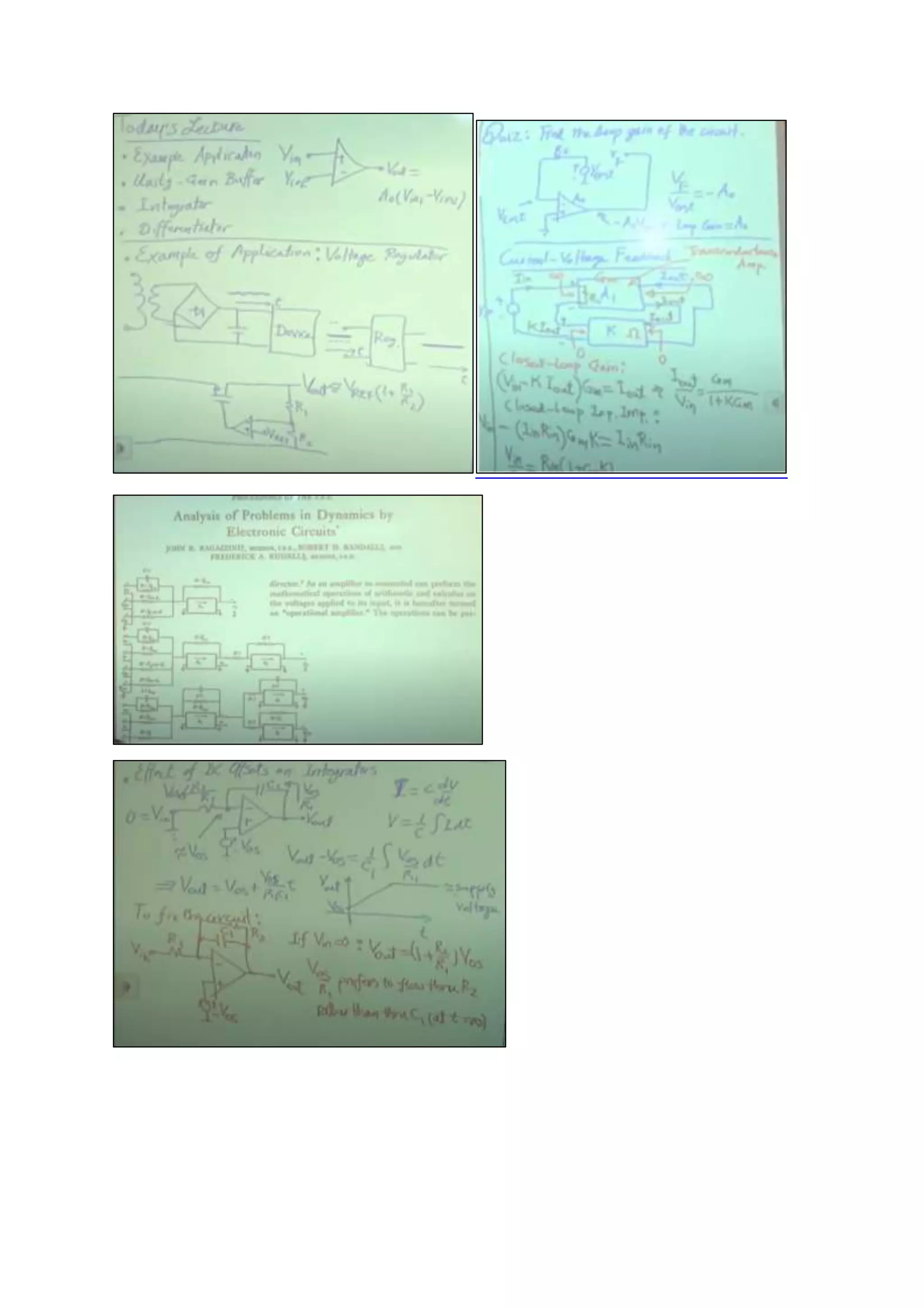
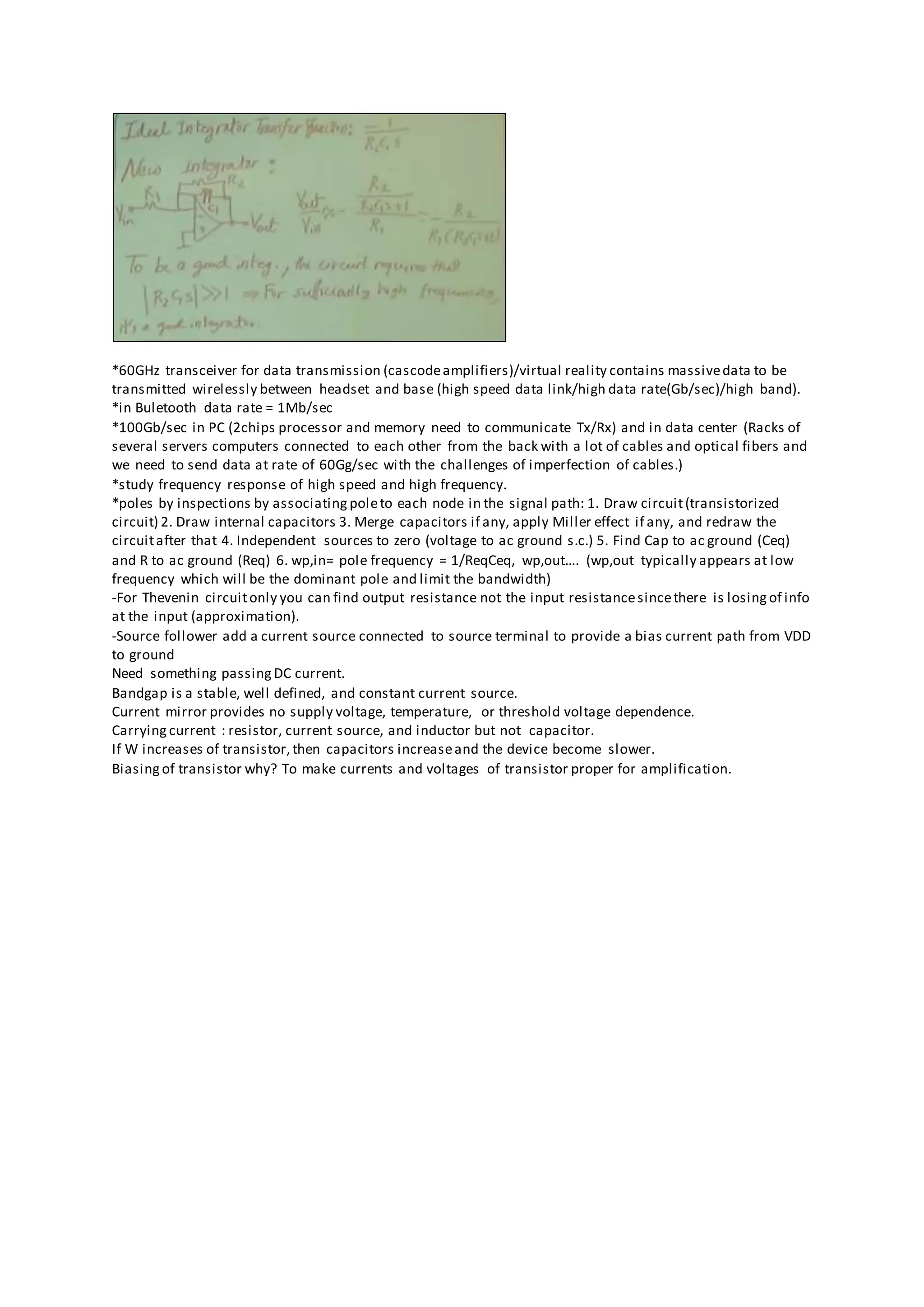
Electronics I Electronics II
BJT and MOS Advanced Circuit Topologies
- Cascode structure
- Current mirror
- Differential pair
Large-signal andsmall signal models Speedlimitations: Frequency response
Amplifier stages Feedback circuits
Biasing
Current sources
Degeneration
Op Amps
Razavi Electronics 1, Lec 9, Other Examples of Diode Circuits, Half-Wave Rectifier
/concept of tracking: Vo=Vi-Ve, Vo tracks Vi perhaps with a constant difference.
/analysis I-V characteristic, input-output characteristic, and time response
If W/L becomes sufficiently large, first gm equation no longer valid use second equation gm=ID/(1.5VT)
mm-Wave frequency beyond 30GHz
Common gate amplifier is used to match impedance of antenna.
No Thevenin equivalent for this since the dependent source is related to the rest of the circuit with which we need
to find equivalent of it. But if dependent source appearinside the box circuit we want to get Thevenin equivalent
it is ok if the rest of the circuit (to right) is valid.
*CB (common base) adds to input node at emitter s series resistorto considerthe output resistorof the
preceding stage or to have emitter degeneration to increase the linearity.
GND
Dependentsource
*60GHz transceiver for data transmission (cascodeamplifiers)/virtual reality contains massivedata to be
transmitted wirelessly between headset and base (high speed data link/high data rate(Gb/sec)/high band).
*in Buletooth data rate = 1Mb/sec
*100Gb/sec in PC (2chips processor and memory need to communicate Tx/Rx) and in data center (Racks of
several servers computers connected to each other from the back with a lot of cables and optical fibers and
we need to send data at rate of 60Gg/sec with the challenges of imperfection of cables.)
*study frequency response of high speed and high frequency.
*poles by inspections by associating poleto each node in the signal path: 1. Draw circuit(transistorized
circuit) 2. Draw internal capacitors 3. Merge capacitors if any, apply Miller effect if any, and redraw the
circuitafter that 4. Independent sources to zero (voltage to ac ground s.c.) 5. Find Cap to ac ground (Ceq)
and R to ac ground (Req) 6. wp,in= pole frequency = 1/ReqCeq, wp,out…. (wp,out typically appears at low
frequency which will be the dominant pole and limit the bandwidth)
-For Thevenin circuitonly you can find output resistance not the input resistancesincethere is losing of info
at the input (approximation).
-Source follower add a current source connected to source terminal to provide a bias current path from VDD
to ground
Need something passing DC current.
Bandgap is a stable, well defined, and constant current source.
Current mirror provides no supply voltage, temperature, or threshold voltage dependence.
Carrying current : resistor, current source, and inductor but not capacitor.
If W increases of transistor,then capacitors increaseand the device become slower.
Biasing of transistor why? To make currents and voltages of transistor proper for amplification.

Electronics i ii razavi

  • 1.
    Electronics I ElectronicsII BJT and MOS Advanced Circuit Topologies - Cascode structure - Current mirror - Differential pair Large-signal andsmall signal models Speedlimitations: Frequency response Amplifier stages Feedback circuits Biasing Current sources Degeneration Op Amps Razavi Electronics 1, Lec 9, Other Examples of Diode Circuits, Half-Wave Rectifier /concept of tracking: Vo=Vi-Ve, Vo tracks Vi perhaps with a constant difference. /analysis I-V characteristic, input-output characteristic, and time response If W/L becomes sufficiently large, first gm equation no longer valid use second equation gm=ID/(1.5VT) mm-Wave frequency beyond 30GHz Common gate amplifier is used to match impedance of antenna. No Thevenin equivalent for this since the dependent source is related to the rest of the circuit with which we need to find equivalent of it. But if dependent source appearinside the box circuit we want to get Thevenin equivalent it is ok if the rest of the circuit (to right) is valid. *CB (common base) adds to input node at emitter s series resistorto considerthe output resistorof the preceding stage or to have emitter degeneration to increase the linearity. GND Dependentsource
  • 3.
    *60GHz transceiver fordata transmission (cascodeamplifiers)/virtual reality contains massivedata to be transmitted wirelessly between headset and base (high speed data link/high data rate(Gb/sec)/high band). *in Buletooth data rate = 1Mb/sec *100Gb/sec in PC (2chips processor and memory need to communicate Tx/Rx) and in data center (Racks of several servers computers connected to each other from the back with a lot of cables and optical fibers and we need to send data at rate of 60Gg/sec with the challenges of imperfection of cables.) *study frequency response of high speed and high frequency. *poles by inspections by associating poleto each node in the signal path: 1. Draw circuit(transistorized circuit) 2. Draw internal capacitors 3. Merge capacitors if any, apply Miller effect if any, and redraw the circuitafter that 4. Independent sources to zero (voltage to ac ground s.c.) 5. Find Cap to ac ground (Ceq) and R to ac ground (Req) 6. wp,in= pole frequency = 1/ReqCeq, wp,out…. (wp,out typically appears at low frequency which will be the dominant pole and limit the bandwidth) -For Thevenin circuitonly you can find output resistance not the input resistancesincethere is losing of info at the input (approximation). -Source follower add a current source connected to source terminal to provide a bias current path from VDD to ground Need something passing DC current. Bandgap is a stable, well defined, and constant current source. Current mirror provides no supply voltage, temperature, or threshold voltage dependence. Carrying current : resistor, current source, and inductor but not capacitor. If W increases of transistor,then capacitors increaseand the device become slower. Biasing of transistor why? To make currents and voltages of transistor proper for amplification.