Download to read offline

![International Research Journal of Engineering and Technology (IRJET) e-ISSN: 2395 -0056
Volume: 04 Issue: 03 | Mar -2017 www.irjet.net p-ISSN: 2395-0072
© 2017, IRJET | Impact Factor value: 5.181 | ISO 9001:2008 Certified Journal | Page 749
3. RESULTS AND ANALYSIS
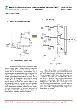
1. Voltage waveform:
Figure 3. Voltage Waveform
From Above fig we studied Voltage Changes
During Fault and After Fault.
In the Fig After 0.1 Sec the single phasing fault is
occur And Breaker Cut the all Three Phases so that
Voltage goes to zero value and induction motor stops.
2. Current Waveform:
Figure 4. Current Waveform
Fig . Shows the current changes in Fault
Here After 0.1 Sec Single Phasing Fault is occur Then
current suddenly increases.
At that time circuit breaker cut the supply so that
current goes to zero value and motor stops.
From the above we studied about the single
phasing of the 3 phase induction motor. Now we
discuss about the some different protection i.
overvoltage, over current, over temperature
protection.
4. CONCLUSION AND FUTURE WORK
Protectionofthreephaseinductionmotorfrom
under voltage, single phasing, over current and phase
reversal provide the smooth running of motor
improves its lifetime and efficiency. Tomakeinduction
motor run efficiently and to protect it from various
faults, sensing circuits have been designed. These
sensing circuit sense the faults occur in an induction
Motor. These faults are monitored by the protection
system and if any fault occurs the motor automatically
turned off.
Hence this prototype model of microcontroller
based protection system is very simple in design,
reliable, highly versatile, and cost effective and gives
quick response.
REFERENCES
[1] D. Kornack and P. Rakic, “Cell Proliferation without
Neurogenesis in Adult Primate Neocortex,” Science, vol.
294, Dec. 2001, pp. 2127-2130,
doi:10.1126/science.1065467.
[2] M. Young, The Technical Writer’s Handbook. Mill Valley,
CA: University Science, 1989.
[3] R. Nicole, “Title of paper with only first word
capitalized,” J. Name Stand. Abbrev., in press.
[4] K. Elissa, “Title of paper if known,” unpublished.](https://image.slidesharecdn.com/irjet-v4i3196-171220102330/85/Three-Phase-Induction-Motor-Protection-Scheme-3-320.jpg)

The document proposes a protection scheme for three phase induction motors against single-phasing faults using MATLAB/SIMULINK software to simulate a single-phasing scenario. It reviews a single-phasing protection using contactors before designing an enhanced protection that protects the motor from under-voltage, over-voltage, voltage unbalance, and over-current. The hardware circuit is controlled by a microcontroller to monitor voltages and currents, and shut off the motor if faults are detected.