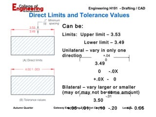
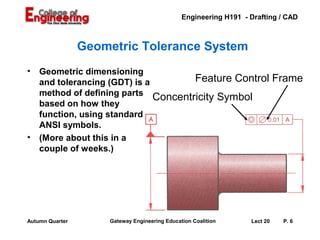
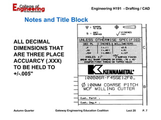
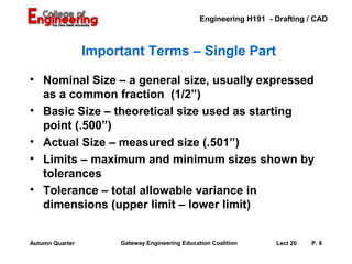
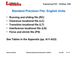
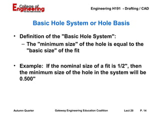
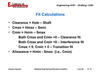
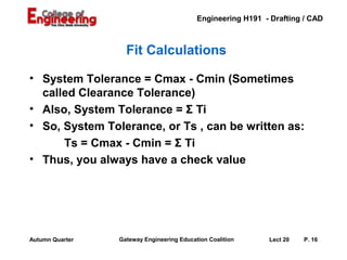
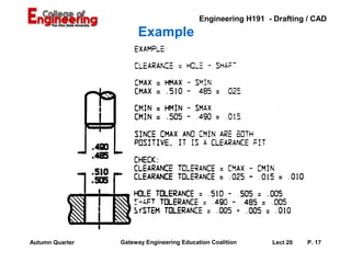
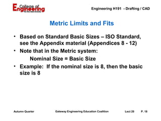
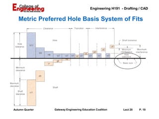
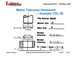
SlideShare a Scribd company logo
1 of 22
Engineering H191 - Drafting / CAD


                 Fits and Tolerances


                          Lecture 20


Autumn Quarter    Gateway Engineering Education Coalition      Lect 20   P. 1
Engineering H191 - Drafting / CAD


           Tolerancing – Control of Variability
• Goals
   – Understand the description and control of
     variability through tolerancing.
   – Use standard tables for tolerancing and
     control of fit
• Reference (BTG)
   – P. 312-317 – Dimensioning for Interchangeable
     Parts
   – P. 349-354 – Standard Tables for Fits
   – P. 358-369 – Geometric Tolerancing

Autumn Quarter     Gateway Engineering Education Coalition      Lect 20   P. 2
Engineering H191 - Drafting / CAD


                 Definition of Tolerance

• Tolerance is the total amount a dimension may
  vary. It is the difference between the maximum
  and minimum limits.
• There is no such thing as an "exact size".
• Tolerance is key to interchangeable parts.


Autumn Quarter     Gateway Engineering Education Coalition      Lect 20   P. 3
Engineering H191 - Drafting / CAD


                 Ways to Express Tolerance

• Direct limits or as tolerance limits applied to a
  dimension
• Geometric tolerances
• Notes referring to specific conditions
• A general tolerance note in title block


Autumn Quarter       Gateway Engineering Education Coalition      Lect 20   P. 4
Engineering H191 - Drafting / CAD

           Direct Limits and Tolerance Values
                         Can be:
                         Limits: Upper limit – 3.53
                                          Lower limit – 3.49
                         Unilateral – vary in only one
                         direction          +.04
                                                         0
                                                  3.49
                                                    0          -.0X
                                                 +.0X -             0
                         Bilateral – vary larger or smaller
                         (may or may not be+.03
                                              same amount)
                                                             -.01
                                                 3.50
Autumn Quarter               +.05 -.01,           +.10 -.20
                   Gateway Engineering Education Coalition                 +/- 0.05
                                                                        Lect 20  P. 5
Engineering H191 - Drafting / CAD


                 Geometric Tolerance System
•   Geometric dimensioning
    and tolerancing (GDT) is a         Feature Control Frame
    method of defining parts
                               Concentricity Symbol
    based on how they
    function, using standard
    ANSI symbols.
•   (More about this in a
    couple of weeks.)


Autumn Quarter       Gateway Engineering Education Coalition      Lect 20   P. 6
Engineering H191 - Drafting / CAD


       Notes and Title Block


ALL DECIMAL
DIMENSIONS THAT
ARE THREE PLACE
ACCUARCY (.XXX)
TO BE HELD TO
+/-.005"


Autumn Quarter   Gateway Engineering Education Coalition      Lect 20   P. 7
Engineering H191 - Drafting / CAD


                 Important Terms – Single Part

• Nominal Size – a general size, usually expressed
  as a common fraction (1/2”)
• Basic Size – theoretical size used as starting
  point (.500”)
• Actual Size – measured size (.501”)
• Limits – maximum and minimum sizes shown by
  tolerances
• Tolerance – total allowable variance in
  dimensions (upper limit – lower limit)


Autumn Quarter        Gateway Engineering Education Coalition      Lect 20   P. 8
Engineering H191 - Drafting / CAD


             Important Terms – Multiple Parts
• Allowance – the minimum clearance or maximum
  interference between parts
• Fit – degree of tightness between two parts
   – Clearance Fit – tolerance of mating parts
     always leave a space
   – Interference Fit – tolerance of mating parts
     always interfere
   – Transition Fit – sometimes interfere,
     sometimes clear
• Tolerance – total allowable variance in
  dimensions (upper limit – lower limit)
Autumn Quarter      Gateway Engineering Education Coalition      Lect 20   P. 9
Engineering H191 - Drafting / CAD


                 Fitting Two Parts


Tolerance of B                                     Tolerance: Clearance
                                                   or     Interference

    Part B
                                   Tolerance of A
                                                       Part A


Autumn Quarter   Gateway Engineering Education Coalition        Lect 20   P. 10
Engineering H191 - Drafting / CAD


                 Shaft and Hole Fits
  Clearance                                                Interference


Autumn Quarter   Gateway Engineering Education Coalition       Lect 20   P. 11
Engineering H191 - Drafting / CAD


                    Shaft and Hole Fits
                         Transition


        CLEARANCE
           FIT
          + .003


Autumn Quarter      Gateway Engineering Education Coalition     Lect 20   P. 12
Engineering H191 - Drafting / CAD


       Standard Precision Fits: English Units

•   Running and sliding fits (RC)
•   Clearance locational fits (LC)
•   Transition locational fits (LT)
•   Interference locational fits (LN)
•   Force and shrink fits (FN)

See Tables in the Appendix (pp. A11-A23)


Autumn Quarter    Gateway Engineering Education Coalition     Lect 20   P. 13
Engineering H191 - Drafting / CAD


             Basic Hole System or Hole Basis

• Definition of the "Basic Hole System":
   – The "minimum size" of the hole is equal to the
     "basic size" of the fit

• Example: If the nominal size of a fit is 1/2", then
  the minimum size of the hole in the system will be
  0.500"


Autumn Quarter      Gateway Engineering Education Coalition     Lect 20   P. 14
Engineering H191 - Drafting / CAD


                  Fit Calculations

• Clearance = Hole – Shaft
• Cmax = Hmax – Smin
• Cmin = Hmin – Smax
      Both Cmax and Cmin >0 – Clearance fit
      Both Cmax and Cmin <0 – Interference fit
      Cmax > 0, Cmin < 0 – Transition fit
• Allowance = Hmin - Smax (i.e., Cmin)


Autumn Quarter   Gateway Engineering Education Coalition     Lect 20   P. 15
Engineering H191 - Drafting / CAD


                   Fit Calculations

• System Tolerance = Cmax - Cmin (Sometimes
  called Clearance Tolerance)
• Also, System Tolerance = Σ Ti
• So, System Tolerance, or Ts , can be written as:
      Ts = Cmax - Cmin = Σ Ti
• Thus, you always have a check value


Autumn Quarter   Gateway Engineering Education Coalition     Lect 20   P. 16
Engineering H191 - Drafting / CAD
                      Example


Autumn Quarter   Gateway Engineering Education Coalition     Lect 20   P. 17
Engineering H191 - Drafting / CAD


                 Metric Limits and Fits

• Based on Standard Basic Sizes – ISO Standard,
  see the Appendix material (Appendices 8 - 12)
• Note that in the Metric system:
      Nominal Size = Basic Size
• Example: If the nominal size is 8, then the basic
  size is 8


Autumn Quarter    Gateway Engineering Education Coalition     Lect 20   P. 18
Engineering H191 - Drafting / CAD


   Metric Preferred Hole Basis System of Fits


Autumn Quarter   Gateway Engineering Education Coalition     Lect 20   P. 19
Engineering H191 - Drafting / CAD


                 Metric Tolerance Homework
                               – Example TOL-1B


Autumn Quarter         Gateway Engineering Education Coalition     Lect 20   P. 20
Engineering H191 - Drafting / CAD


                 Good Review Material

• BTG Chapter 7
   – Dimensions and Tolerances
   – Pages 290-335

• BTG Chapter 8
   – Dimensions For Production
   – Pages 340-375


Autumn Quarter    Gateway Engineering Education Coalition     Lect 20   P. 21
Engineering H191 - Drafting / CAD


                      Assignments

• Dwg 39 – G27 – Tolerances – Single Fits
   – Calculate the missing values for each
     situation.
   – Use the tables for preferred limits and fits for
     cylindrical parts.

• Dwg 40 – TOL–1A – Metric Tolerances
   – Using the given nominal sizes and fit
     specifications, calculate remaining values.

Autumn Quarter   Gateway Engineering Education Coalition     Lect 20   P. 22

More Related Content

What's hot

limits,fits and tolerances
limits,fits and toleranceslimits,fits and tolerances
limits,fits and tolerancesJOSE BABU
 
Engineering Drawing: Chapter 11 thread fastener
Engineering Drawing: Chapter 11 thread fastenerEngineering Drawing: Chapter 11 thread fastener
Engineering Drawing: Chapter 11 thread fastenermokhtar
 
Ipec limits fits
Ipec limits fitsIpec limits fits
Ipec limits fitsManoj Yadav
 
Fasteners & fastening
Fasteners & fasteningFasteners & fastening
Fasteners & fasteningAbrish Gebru
 
Sheet metal design
Sheet metal designSheet metal design
Sheet metal designHien Dinh
 
Dimensional Tolerances
Dimensional TolerancesDimensional Tolerances
Dimensional Tolerancess2francetrip
 
Gd&t introductory presentation
Gd&t introductory presentationGd&t introductory presentation
Gd&t introductory presentationSimranjit Singh
 
GD&T Fundamentals Training
GD&T Fundamentals TrainingGD&T Fundamentals Training
GD&T Fundamentals TrainingBESTSOLUTIONS4
 
14 symbols of gd&t
14 symbols of gd&t14 symbols of gd&t
14 symbols of gd&tSree Lakshmy
 
Manufacturing Engineering 2, cutting tools and tool holders
Manufacturing Engineering 2, cutting tools and tool holdersManufacturing Engineering 2, cutting tools and tool holders
Manufacturing Engineering 2, cutting tools and tool holdersGaurav Mistry
 
Ch 24 limit, tolerance &amp; fits
Ch 24 limit, tolerance &amp; fitsCh 24 limit, tolerance &amp; fits
Ch 24 limit, tolerance &amp; fitsNandan Choudhary
 
Milling & Gear Cutting
Milling & Gear CuttingMilling & Gear Cutting
Milling & Gear CuttingKonal Singh
 
Clamping and Clamping Devices
Clamping and Clamping DevicesClamping and Clamping Devices
Clamping and Clamping DevicesAmruta Rane
 

What's hot (20)

limits,fits and tolerances
limits,fits and toleranceslimits,fits and tolerances
limits,fits and tolerances
 
Sheet Metal Working & Process
Sheet Metal Working & ProcessSheet Metal Working & Process
Sheet Metal Working & Process
 
Engineering Drawing: Chapter 11 thread fastener
Engineering Drawing: Chapter 11 thread fastenerEngineering Drawing: Chapter 11 thread fastener
Engineering Drawing: Chapter 11 thread fastener
 
Ipec limits fits
Ipec limits fitsIpec limits fits
Ipec limits fits
 
Jigs and fixtures imp
Jigs and fixtures impJigs and fixtures imp
Jigs and fixtures imp
 
GD&T - PPT
GD&T - PPTGD&T - PPT
GD&T - PPT
 
Fasteners & fastening
Fasteners & fasteningFasteners & fastening
Fasteners & fastening
 
Sheet metal design
Sheet metal designSheet metal design
Sheet metal design
 
Drill bushes
Drill bushesDrill bushes
Drill bushes
 
Assembly modelling
Assembly modellingAssembly modelling
Assembly modelling
 
Limits, fits and tolerances
Limits, fits and tolerancesLimits, fits and tolerances
Limits, fits and tolerances
 
Dimensional Tolerances
Dimensional TolerancesDimensional Tolerances
Dimensional Tolerances
 
Gd&t introductory presentation
Gd&t introductory presentationGd&t introductory presentation
Gd&t introductory presentation
 
Tolerance analysis
Tolerance analysisTolerance analysis
Tolerance analysis
 
GD&T Fundamentals Training
GD&T Fundamentals TrainingGD&T Fundamentals Training
GD&T Fundamentals Training
 
14 symbols of gd&t
14 symbols of gd&t14 symbols of gd&t
14 symbols of gd&t
 
Manufacturing Engineering 2, cutting tools and tool holders
Manufacturing Engineering 2, cutting tools and tool holdersManufacturing Engineering 2, cutting tools and tool holders
Manufacturing Engineering 2, cutting tools and tool holders
 
Ch 24 limit, tolerance &amp; fits
Ch 24 limit, tolerance &amp; fitsCh 24 limit, tolerance &amp; fits
Ch 24 limit, tolerance &amp; fits
 
Milling & Gear Cutting
Milling & Gear CuttingMilling & Gear Cutting
Milling & Gear Cutting
 
Clamping and Clamping Devices
Clamping and Clamping DevicesClamping and Clamping Devices
Clamping and Clamping Devices
 

Lecture 20 fits and tolerances

  • 1. Engineering H191 - Drafting / CAD Fits and Tolerances Lecture 20 Autumn Quarter Gateway Engineering Education Coalition Lect 20 P. 1
  • 2. Engineering H191 - Drafting / CAD Tolerancing – Control of Variability • Goals – Understand the description and control of variability through tolerancing. – Use standard tables for tolerancing and control of fit • Reference (BTG) – P. 312-317 – Dimensioning for Interchangeable Parts – P. 349-354 – Standard Tables for Fits – P. 358-369 – Geometric Tolerancing Autumn Quarter Gateway Engineering Education Coalition Lect 20 P. 2
  • 3. Engineering H191 - Drafting / CAD Definition of Tolerance • Tolerance is the total amount a dimension may vary. It is the difference between the maximum and minimum limits. • There is no such thing as an "exact size". • Tolerance is key to interchangeable parts. Autumn Quarter Gateway Engineering Education Coalition Lect 20 P. 3
  • 4. Engineering H191 - Drafting / CAD Ways to Express Tolerance • Direct limits or as tolerance limits applied to a dimension • Geometric tolerances • Notes referring to specific conditions • A general tolerance note in title block Autumn Quarter Gateway Engineering Education Coalition Lect 20 P. 4
  • 5. Engineering H191 - Drafting / CAD Direct Limits and Tolerance Values Can be: Limits: Upper limit – 3.53 Lower limit – 3.49 Unilateral – vary in only one direction +.04 0 3.49 0 -.0X +.0X - 0 Bilateral – vary larger or smaller (may or may not be+.03 same amount) -.01 3.50 Autumn Quarter +.05 -.01, +.10 -.20 Gateway Engineering Education Coalition +/- 0.05 Lect 20 P. 5
  • 6. Engineering H191 - Drafting / CAD Geometric Tolerance System • Geometric dimensioning and tolerancing (GDT) is a Feature Control Frame method of defining parts Concentricity Symbol based on how they function, using standard ANSI symbols. • (More about this in a couple of weeks.) Autumn Quarter Gateway Engineering Education Coalition Lect 20 P. 6
  • 7. Engineering H191 - Drafting / CAD Notes and Title Block ALL DECIMAL DIMENSIONS THAT ARE THREE PLACE ACCUARCY (.XXX) TO BE HELD TO +/-.005" Autumn Quarter Gateway Engineering Education Coalition Lect 20 P. 7
  • 8. Engineering H191 - Drafting / CAD Important Terms – Single Part • Nominal Size – a general size, usually expressed as a common fraction (1/2”) • Basic Size – theoretical size used as starting point (.500”) • Actual Size – measured size (.501”) • Limits – maximum and minimum sizes shown by tolerances • Tolerance – total allowable variance in dimensions (upper limit – lower limit) Autumn Quarter Gateway Engineering Education Coalition Lect 20 P. 8
  • 9. Engineering H191 - Drafting / CAD Important Terms – Multiple Parts • Allowance – the minimum clearance or maximum interference between parts • Fit – degree of tightness between two parts – Clearance Fit – tolerance of mating parts always leave a space – Interference Fit – tolerance of mating parts always interfere – Transition Fit – sometimes interfere, sometimes clear • Tolerance – total allowable variance in dimensions (upper limit – lower limit) Autumn Quarter Gateway Engineering Education Coalition Lect 20 P. 9
  • 10. Engineering H191 - Drafting / CAD Fitting Two Parts Tolerance of B Tolerance: Clearance or Interference Part B Tolerance of A Part A Autumn Quarter Gateway Engineering Education Coalition Lect 20 P. 10
  • 11. Engineering H191 - Drafting / CAD Shaft and Hole Fits Clearance Interference Autumn Quarter Gateway Engineering Education Coalition Lect 20 P. 11
  • 12. Engineering H191 - Drafting / CAD Shaft and Hole Fits Transition CLEARANCE FIT + .003 Autumn Quarter Gateway Engineering Education Coalition Lect 20 P. 12
  • 13. Engineering H191 - Drafting / CAD Standard Precision Fits: English Units • Running and sliding fits (RC) • Clearance locational fits (LC) • Transition locational fits (LT) • Interference locational fits (LN) • Force and shrink fits (FN) See Tables in the Appendix (pp. A11-A23) Autumn Quarter Gateway Engineering Education Coalition Lect 20 P. 13
  • 14. Engineering H191 - Drafting / CAD Basic Hole System or Hole Basis • Definition of the "Basic Hole System": – The "minimum size" of the hole is equal to the "basic size" of the fit • Example: If the nominal size of a fit is 1/2", then the minimum size of the hole in the system will be 0.500" Autumn Quarter Gateway Engineering Education Coalition Lect 20 P. 14
  • 15. Engineering H191 - Drafting / CAD Fit Calculations • Clearance = Hole – Shaft • Cmax = Hmax – Smin • Cmin = Hmin – Smax Both Cmax and Cmin >0 – Clearance fit Both Cmax and Cmin <0 – Interference fit Cmax > 0, Cmin < 0 – Transition fit • Allowance = Hmin - Smax (i.e., Cmin) Autumn Quarter Gateway Engineering Education Coalition Lect 20 P. 15
  • 16. Engineering H191 - Drafting / CAD Fit Calculations • System Tolerance = Cmax - Cmin (Sometimes called Clearance Tolerance) • Also, System Tolerance = Σ Ti • So, System Tolerance, or Ts , can be written as: Ts = Cmax - Cmin = Σ Ti • Thus, you always have a check value Autumn Quarter Gateway Engineering Education Coalition Lect 20 P. 16
  • 17. Engineering H191 - Drafting / CAD Example Autumn Quarter Gateway Engineering Education Coalition Lect 20 P. 17
  • 18. Engineering H191 - Drafting / CAD Metric Limits and Fits • Based on Standard Basic Sizes – ISO Standard, see the Appendix material (Appendices 8 - 12) • Note that in the Metric system: Nominal Size = Basic Size • Example: If the nominal size is 8, then the basic size is 8 Autumn Quarter Gateway Engineering Education Coalition Lect 20 P. 18
  • 19. Engineering H191 - Drafting / CAD Metric Preferred Hole Basis System of Fits Autumn Quarter Gateway Engineering Education Coalition Lect 20 P. 19
  • 20. Engineering H191 - Drafting / CAD Metric Tolerance Homework – Example TOL-1B Autumn Quarter Gateway Engineering Education Coalition Lect 20 P. 20
  • 21. Engineering H191 - Drafting / CAD Good Review Material • BTG Chapter 7 – Dimensions and Tolerances – Pages 290-335 • BTG Chapter 8 – Dimensions For Production – Pages 340-375 Autumn Quarter Gateway Engineering Education Coalition Lect 20 P. 21
  • 22. Engineering H191 - Drafting / CAD Assignments • Dwg 39 – G27 – Tolerances – Single Fits – Calculate the missing values for each situation. – Use the tables for preferred limits and fits for cylindrical parts. • Dwg 40 – TOL–1A – Metric Tolerances – Using the given nominal sizes and fit specifications, calculate remaining values. Autumn Quarter Gateway Engineering Education Coalition Lect 20 P. 22

Editor's Notes

  1. Instructor: Some students have problems with tolerances and it is worth taking this lesson slowly and making sure that all of the students are with you. If you are not using the Boyer Technical Graphics book, you will need to find these sections in your text book.
  2. Instructor: Emphasize that we are working on getting the maximum and minimum sizes for a particular part first. Then we will worry about parts fitting together. Also remind them that the closer you hold a tolerance the higher the cost of an item.
  3. Instructor: There are a variety of ways to specify part sizes. This set of notes is going to use upper and lower limits most of the time. Just as a drawing must have the scale listed in the title block it must also have the overall tolerance of parts and part features. Typically it might be something like: All parts are +/-.01 unless otherwise specified.
  4. Instructor: Here are some of the ways to specify the limits on parts.
  5. Instructor: There is large body of knowledge that deals with Geometric Dimensioning and Tolerancing. We are introducing it here so that the students have an idea of what to look for in drawings that have GDT. The A in the sign is the base dimension – in this case the diameter. The rectangular box specifies that the cylinder on the right end must be concentric with the cylinder labeled A within 0.01 inch
  6. Instructor: Point out to your students that the overall tolerance on this drawing depends on the number of decimal places in the given dimension. Note that they specify the tolerance on angles (+/- 1 degree) as well as the other dimensions. In this case, there is also an overall surface finish specified – the symbol that looks like a check mark.
  7. Instructor: Take your time going through this slide. Make sure that they understand each definition.
  8. Instructor: Note that the definitions on the previous page dealt with one part and how it varies. On this page the definitions deal with how parts fit together.
  9. Instructor: The blue area represents the fit between A and B where the dark area represent the variance in the size of A and B
  10. Instructor: Here is another way to look at how parts fit together. In this illustration, the beige area represents the variation in size of one part and it is easy to see that on the left side we have a clearance fit where the smallest hole is larger than the largest shaft. This is called a clearance fit. The opposite is true on the other end. This is a force fit, shrink fit or an interference fit. Note the small print at the bottom: Allowance always equals the smallest hole minus the largest shaft. When you have an interference fit the allowance is negative.
  11. Instructor: This figure is slightly different than the previous one. Here they have put the smallest shaft on the left end and the largest shaft on the right side. The shaft on the left clears by .003 inch while the one on the right interferes by .002 inch.
  12. Instructor: Here are the types of fits specified by ANSI. The tables are found in the Appendices in most graphics books.
  13. Instructor: There needs to be some order to doing tolerances and in this case the choice was to make the smallest hole the basic size. If the nominal size is given as a common fraction (1/2) then the basic size is .500 or .5000 depending on the type of fit.
  14. Instructor: Go through this table of equations with your class. These are the equations that they will use to complete today’s exercises.
  15. Instructor: Here are the equations to check your work by looking at the system tolerance – the sum of the tolerances of the parts.
  16. Instructor: Here is an example of looking at the tolerance of each part and the fit tolerance.
  17. Instructor: In the metric system the nominal size is equal to the basic size given with the correct number of decimal places.
  18. Instructor: When working in the metric system they use a series of letters and numbers where the capital letters represent the hole and the lower case letters represent the shaft sizes.
  19. Instructor: Here is an example done in the metric system.
  20. Instructor: Make sure the students are reading the text book. You might want to put your text under the document camera (if you use one) to show them figures from the chapter and to show them examples from the Appendices.
  21. Instructor: If you do not use a document camera make a copy of one of the pages from the Appendix at a large enough scale to be easily read when projected and show them how the table works.