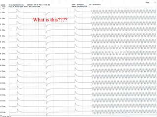
Shehzad Hussain
Technologist
 Calibration is a procedure to ensure through the checks
that the EEG machine is fit for the purpose.
 It is set of sequential steps to test, compare and adjust the
measuring instrument before recording.
 Ensure that the instrument is fit for the purpose
 Helps interpreter in correct measurements
 Lets interpreter know the minor deviations
while reporting
 Helps to compare the recording with previous.
 Bio calibration assesses the response of the
amplifiers, filters and the recording apparatus on a
complex biological signal. Electrode FP1 and O2
are connected to all amplifier inputs. The
recordings for all channels should be identical.
 SIGNIFICANCE OF BIOLOGICAL CALIBRATION:
 It is a montage because a fixed pattern is set in
which throughout activity of 18 channels is
obtained.
 It reassures the machine calibration through
amplifiers.
Then we can interpretate
wrong and the result will
be wrong.
Either we make a normal
EEG abnormal.
Conventional EEG machine
Schematic Diagram
1. Sufficient ink
2. Sufficient paper
3. Paper speed
4. Pen alignment
5. Pen centering
6. Damping
7) Time constant or LFF
8) High frequency filter (HFF)
9) Sensitivity
10) Step gain
11) Amplitude linearity
12) Noise level
Digital Machine
Analog Machine
 Ensure that as per plan of the recording their is
more than enough paper/Disc space.
 Before taking printout sufficient paper is
present in the printer.
What’s wrong if not checked?
 Insufficient paper will lead cessation of live
recording
 Cessation may lead to miss:
1. any paroxysmal event
2. a brief Interictal abnormality
3. onset of a seizure.
Sufficient ink should be present in the tube
of writer/ printer cartridge should not be
empty.
Consequences:
1. any paroxysmal event
2. a brief Interictal abnormality
3. onset of a seizure.
4. Loss of paper
 It is the speed at which the paper roles off through
the pen writer.
 Standard paper speed is 3cm/sec or
30millimeter/second
 Standard paper size is 30 cm/fold
 Slow Paper Speed:
 Used with time constant to make the slowing
prominent.
 Like 15mm/sec.
 Fast paper Speed:
 It is used to check the onset of an event.
 60mm/sec
 Paper speed could be checked in two ways:
1. Manually by;
by measuring the distance simultaneously
running the paper and monitoring the time
lapsed.
Distance/time lapsed= paper speed.
2. Automatically by;
By using the time marker of the machine.
Distance=27cm, Time =30seconds P.S=27cm/30sec= 0.9cm/sec or 9mm/sec
 Misinterpretations of frequency
 Misinterpretation of waveform duration
 Wave morphology could change like spike
could appear as sharp wave and sharp
wave as slow wave.
 In digital EEG machine internal setting of
machine is difficult, interfere can cause other
consequences. So….
 If paper speed is wrong then inform the
biomedical engineer to correct it.
 All pens should start and stop simultaneously
in a perpendicular line.
 Could be checked by drawing a straight line
perpendicular to the paper drive by using set
squares
 This can be done with or without calibration
signal
Misalignment of Pens
 If not aligned then:
1. Will cause distortion of focal activity
2. Misinterpretation of EEG
 Causes of misalignment:
1. More/ less Bent of stylus nib
2. Worn out stylus nib (Nib can be bent inward
or outward).
 Corrections of Pen alignment:
Simply change the stylus, all pens should be
change simultaneously.
 All pens should be in the center ( at Zero line)
of the pen writer/galvano meter.
 How it is checked
 There should be no deflection off the base line
while starting the machine or switch on and off
the amplifier with no calibration signal.
Out Pen centering in conventional EEG
Mechanically Out Pen centering
Electrical out Pen centering
 Types of problems:
1. Mechanical pen centering
Apparently pens are not in the center of the
galvano meter.
1. 2. Electrical pen centering
While giving the electrical signal to the pens
and simultaneously on and off the switch of
galvano meter. Ideally there should no
deflection.
 Mechanical pen centering problem means that
the pen are not staying at zero line apparently
when the machine is switched on.
 Electrical pen centering problem means that the
pens are deviating from base (zero) line when
amplifier switched on or off without any
calibration signal while the machine is
switched on.
Potentio meter
 Effect on EEG recording:
1. Decrease in the high amplitude activities
2. Pseudo asymmetry of amplitudes
3. Decrease in the dynamic range
4. Distortion in the channel layout
 1. Correct the mechanical pen centering by
Allen Wrench-key, pull out the pen from its
base form the galvanometer and fix it on the
zero line.
 2. Correct the electrical pen centering by switch
on and off the amplifier and adjusting the
potentiometer. There should be no deflection
off the zero line.
 3. Again adjusting the mechanical pen
centering
 It is the pressure of the pens on the paper
 This could be
 Mechanical pressure on pens called mechanical
damping
 Electrical damping undesirable resistance in
the GVM circuit called electrical damping.
 Standard damping is 2.5 gram.
Over Damping
Under Damping
 There should be no rounding or overshoot of
peak while the TC is set to 0.1second and HFF
is set to 70 Hz as an standard parameters.
 Causes of mechanical damping
1. Excessive / loose tightening of pen holding
screw.
2. Worn out pens
 Causes of electrical damping
1. Excessive / low resistance in the GVM circuit
How these can be corrected;
 Mechanical damping should be considered
first.
 By using pen pressure tool and adjusting the
central pen holding screw to get critical
damping
 By changing pen if worn out
 By adjusting pen damping potentiometer to get
critical damping
1. Over Damping (under shoot)
Excessive pressure on pens will result in
over damping or Under shoot.
Decrease in voltages measurement b/c of
rounding of peak.
2. Under Damping (over shoot)
low pressure on pens will result under
damping or over shoot.
Increase in voltage measurement b/c of
overshoot at peak.
 Undershoot result in rounding of peak of
waveform
 pseudo amplitude reduction.
 Overshoot will result in pseudo voltage
increase.
 Pens can collide with each other and can break.
 Both will result in waveform distortion.
 It is the low frequency filter/High pass filter
 One of the most important component of the circuit
which can make EEG normal and abnormal.
 Defined as the time content is the time required for
the pen to fall 63% from the peak of the deflection
produced.
 T.C depends upon the size of the capacitor.
 T.C effects the decaying signal of the Calibration
signal.
 It is measured in second but can be converted
into frequency
 Formula for conversion is:
f = 1/ 2 T.C
 Record a known calibration signal
 Ideally at standard parameters setting of:
Sen = 7 V/ mm
Input voltage = 50 V
Paper speed = 30 mm / sec
TC = ?
 Measure 1/3 ( 37%) of the total pen deflection
from the base line and mark it
 Draw a base line crossing the initial deflection
till is merge back to the baseline
 Draw a parallel line to the baseline at the mark
mentioned above to get crossing at decaying
curve.
 Draw a perpendicular using set square from
this point to the baseline
 Measure the distance from the initial deflection
to this bisecting perpendicular
 Divide this distance with paper speed to get
TC.
 Effects on EEG / usage
 It attenuates the low frequencies.
 Could be used with appropriate paper speed to
show focal abnormalities prominent.
 This can be used with extreme care as in the
case of sweating artifacts b/c it can make an
EEG normal or abnormal.
 Also called Low pass filter.
 It mainly effects the rise time in calibration
signal.
 In EEG we are interested in the high frequency
of 70 Hz.
 It allows low frequencies to pass and stop
higher frequencies.
 If not calibrated, then contact to Bio-Medical
engineer to fix it as this can be the resistor
dysfunction in HFF circuit
Effects of the HFF on EEG:
1. It drops the amplitude by 30% i.e. 3db/octave.
2. Causes rounding of peak which may the
morphology of the waveforms.
3. Amplitude reduction which may lead to
asymmetry
4. Phase Shift will distort the focus
Voltage attenuation
 This is the magnitude of input voltage requires to
produce a standard pen deflection i.e. (known input
voltage to produce known pen deflection)
 Can be checked by inducing a known input
calibration voltage (50 V) and measuring the pen
deflection under standard parameters i.e. HFF 70Hz,
LFF 0.1 Sec.
 Sensitivity=input voltage/Pen deflection=50uV/7.1mm
= _____V / mm
 All channels should have the same sensitivity
as standard
 If input voltage is change the output pen
deflection should be change in direct
proportion.
 sensitivity is adjusted to avoid cutting of the
waveforms.
 Effects on the EEG:
1. Misinterpretation of amplitudes.
2. Wrong sensitivity setting in individual
channels will lead to pseudo asymmetry
3. Blocking of channels will cause difficulty in
measurement of voltage and recognition of
spike or sharp activity
 A recording channel is said to be linear if
the pen deflection is proportional to the
amplitude of the input signal applied.
 If input voltage is doubled the pen
deflection should be doubled in all
channels.
 How it can be checked
1. Keeping sensitivity constant e.g 100uV/cm
2. By inducing calibrator signals of 20,50 & 100uV.
3. Measuring the calibration signal.
 P.D=100 micro volt/10 micro volt
 =1mm
 P.D=100 micro volt/20 micro volt
 =5mm
 P.D=100 micro volt/50 micro volt
 =2mm
1. If not controlled, then call Bio-Medical engineer
 Characteristics:
 Every system has an amplitude level beyond
which non-linear distortion occurs.
 The range over which the system is linear is
called dynamic range.
 Non-linearity can occur at very low pen
deflection because of pressure or default in the
writer system causing small amplitude
calibration signal (1 or 2 mm) to be rounded.
 This is the ratio of signal voltage obtained at the
output of amplifier to signal voltage applied at the
input.
 For example if an amplifier is set to give a voltage of
10V for an input voltage of 10uV then the gain is said
to be 1 million.
 In contrast to sensitivity, gain is predefined
 it increases with increasing amplification.
 Gain is not as important than sensitivity because gain
is not measured. It is prebuilt in the system.
 Effect on the EEG
1. Misinterpretations of voltages
2. Pseudo Asymmetry if this happen in
individual channels.
3. For correction call the bio-medical engineer
 All electrical circuit has small vibration in the
components of the circuit if current pass
through them because of electron movements
 This give a small output even if there is no
external signal
 This is called noise level of the measuring unit.
 How to check it
1. Switch on the machine
2. Disconnect the junction box to avoid any input
signal
3. Set the sensitivity to 2uV/mm
4. Record the trace
5. A peak to peak 2 mm deflection is acceptable.
 Effect on EEG
1. Very low voltage EEG like ECS recording
would be misinterpreted because of noise level
2. How it is corrected
If there is a problem call bio-medical engineer
What is this????
Square wave
Calibration
Sine wave
Calibration
 Basic principles of digital and analog
EEG,Fisch and Spehlmann’s EEG Primer

Eeg machine calibration

  • 1.
  • 2.
     Calibration isa procedure to ensure through the checks that the EEG machine is fit for the purpose.  It is set of sequential steps to test, compare and adjust the measuring instrument before recording.
  • 3.
     Ensure thatthe instrument is fit for the purpose  Helps interpreter in correct measurements  Lets interpreter know the minor deviations while reporting  Helps to compare the recording with previous.
  • 4.
     Bio calibrationassesses the response of the amplifiers, filters and the recording apparatus on a complex biological signal. Electrode FP1 and O2 are connected to all amplifier inputs. The recordings for all channels should be identical.  SIGNIFICANCE OF BIOLOGICAL CALIBRATION:  It is a montage because a fixed pattern is set in which throughout activity of 18 channels is obtained.  It reassures the machine calibration through amplifiers.
  • 5.
    Then we caninterpretate wrong and the result will be wrong. Either we make a normal EEG abnormal.
  • 6.
  • 7.
  • 8.
    1. Sufficient ink 2.Sufficient paper 3. Paper speed 4. Pen alignment 5. Pen centering 6. Damping
  • 9.
    7) Time constantor LFF 8) High frequency filter (HFF) 9) Sensitivity 10) Step gain 11) Amplitude linearity 12) Noise level
  • 10.
  • 11.
  • 12.
     Ensure thatas per plan of the recording their is more than enough paper/Disc space.  Before taking printout sufficient paper is present in the printer. What’s wrong if not checked?
  • 13.
     Insufficient paperwill lead cessation of live recording  Cessation may lead to miss: 1. any paroxysmal event 2. a brief Interictal abnormality 3. onset of a seizure.
  • 14.
    Sufficient ink shouldbe present in the tube of writer/ printer cartridge should not be empty. Consequences: 1. any paroxysmal event 2. a brief Interictal abnormality 3. onset of a seizure. 4. Loss of paper
  • 15.
     It isthe speed at which the paper roles off through the pen writer.  Standard paper speed is 3cm/sec or 30millimeter/second  Standard paper size is 30 cm/fold  Slow Paper Speed:  Used with time constant to make the slowing prominent.  Like 15mm/sec.  Fast paper Speed:  It is used to check the onset of an event.  60mm/sec
  • 16.
     Paper speedcould be checked in two ways: 1. Manually by; by measuring the distance simultaneously running the paper and monitoring the time lapsed. Distance/time lapsed= paper speed. 2. Automatically by; By using the time marker of the machine.
  • 17.
    Distance=27cm, Time =30secondsP.S=27cm/30sec= 0.9cm/sec or 9mm/sec
  • 18.
     Misinterpretations offrequency  Misinterpretation of waveform duration  Wave morphology could change like spike could appear as sharp wave and sharp wave as slow wave.
  • 19.
     In digitalEEG machine internal setting of machine is difficult, interfere can cause other consequences. So….  If paper speed is wrong then inform the biomedical engineer to correct it.
  • 20.
     All pensshould start and stop simultaneously in a perpendicular line.  Could be checked by drawing a straight line perpendicular to the paper drive by using set squares  This can be done with or without calibration signal
  • 21.
  • 22.
     If notaligned then: 1. Will cause distortion of focal activity 2. Misinterpretation of EEG
  • 23.
     Causes ofmisalignment: 1. More/ less Bent of stylus nib 2. Worn out stylus nib (Nib can be bent inward or outward).  Corrections of Pen alignment: Simply change the stylus, all pens should be change simultaneously.
  • 24.
     All pensshould be in the center ( at Zero line) of the pen writer/galvano meter.  How it is checked  There should be no deflection off the base line while starting the machine or switch on and off the amplifier with no calibration signal.
  • 25.
    Out Pen centeringin conventional EEG
  • 26.
  • 27.
  • 28.
     Types ofproblems: 1. Mechanical pen centering Apparently pens are not in the center of the galvano meter. 1. 2. Electrical pen centering While giving the electrical signal to the pens and simultaneously on and off the switch of galvano meter. Ideally there should no deflection.
  • 29.
     Mechanical pencentering problem means that the pen are not staying at zero line apparently when the machine is switched on.  Electrical pen centering problem means that the pens are deviating from base (zero) line when amplifier switched on or off without any calibration signal while the machine is switched on.
  • 30.
  • 32.
     Effect onEEG recording: 1. Decrease in the high amplitude activities 2. Pseudo asymmetry of amplitudes 3. Decrease in the dynamic range 4. Distortion in the channel layout
  • 33.
     1. Correctthe mechanical pen centering by Allen Wrench-key, pull out the pen from its base form the galvanometer and fix it on the zero line.  2. Correct the electrical pen centering by switch on and off the amplifier and adjusting the potentiometer. There should be no deflection off the zero line.  3. Again adjusting the mechanical pen centering
  • 34.
     It isthe pressure of the pens on the paper  This could be  Mechanical pressure on pens called mechanical damping  Electrical damping undesirable resistance in the GVM circuit called electrical damping.  Standard damping is 2.5 gram.
  • 35.
  • 36.
     There shouldbe no rounding or overshoot of peak while the TC is set to 0.1second and HFF is set to 70 Hz as an standard parameters.
  • 37.
     Causes ofmechanical damping 1. Excessive / loose tightening of pen holding screw. 2. Worn out pens  Causes of electrical damping 1. Excessive / low resistance in the GVM circuit
  • 38.
    How these canbe corrected;  Mechanical damping should be considered first.  By using pen pressure tool and adjusting the central pen holding screw to get critical damping  By changing pen if worn out  By adjusting pen damping potentiometer to get critical damping
  • 39.
    1. Over Damping(under shoot) Excessive pressure on pens will result in over damping or Under shoot. Decrease in voltages measurement b/c of rounding of peak. 2. Under Damping (over shoot) low pressure on pens will result under damping or over shoot. Increase in voltage measurement b/c of overshoot at peak.
  • 40.
     Undershoot resultin rounding of peak of waveform  pseudo amplitude reduction.  Overshoot will result in pseudo voltage increase.  Pens can collide with each other and can break.  Both will result in waveform distortion.
  • 42.
     It isthe low frequency filter/High pass filter  One of the most important component of the circuit which can make EEG normal and abnormal.  Defined as the time content is the time required for the pen to fall 63% from the peak of the deflection produced.  T.C depends upon the size of the capacitor.  T.C effects the decaying signal of the Calibration signal.
  • 44.
     It ismeasured in second but can be converted into frequency  Formula for conversion is: f = 1/ 2 T.C
  • 45.
     Record aknown calibration signal  Ideally at standard parameters setting of: Sen = 7 V/ mm Input voltage = 50 V Paper speed = 30 mm / sec TC = ?
  • 46.
     Measure 1/3( 37%) of the total pen deflection from the base line and mark it  Draw a base line crossing the initial deflection till is merge back to the baseline  Draw a parallel line to the baseline at the mark mentioned above to get crossing at decaying curve.
  • 47.
     Draw aperpendicular using set square from this point to the baseline  Measure the distance from the initial deflection to this bisecting perpendicular  Divide this distance with paper speed to get TC.
  • 48.
     Effects onEEG / usage  It attenuates the low frequencies.  Could be used with appropriate paper speed to show focal abnormalities prominent.  This can be used with extreme care as in the case of sweating artifacts b/c it can make an EEG normal or abnormal.
  • 49.
     Also calledLow pass filter.  It mainly effects the rise time in calibration signal.  In EEG we are interested in the high frequency of 70 Hz.  It allows low frequencies to pass and stop higher frequencies.
  • 52.
     If notcalibrated, then contact to Bio-Medical engineer to fix it as this can be the resistor dysfunction in HFF circuit
  • 53.
    Effects of theHFF on EEG: 1. It drops the amplitude by 30% i.e. 3db/octave. 2. Causes rounding of peak which may the morphology of the waveforms. 3. Amplitude reduction which may lead to asymmetry 4. Phase Shift will distort the focus
  • 54.
  • 55.
     This isthe magnitude of input voltage requires to produce a standard pen deflection i.e. (known input voltage to produce known pen deflection)  Can be checked by inducing a known input calibration voltage (50 V) and measuring the pen deflection under standard parameters i.e. HFF 70Hz, LFF 0.1 Sec.  Sensitivity=input voltage/Pen deflection=50uV/7.1mm = _____V / mm
  • 57.
     All channelsshould have the same sensitivity as standard  If input voltage is change the output pen deflection should be change in direct proportion.  sensitivity is adjusted to avoid cutting of the waveforms.
  • 58.
     Effects onthe EEG: 1. Misinterpretation of amplitudes. 2. Wrong sensitivity setting in individual channels will lead to pseudo asymmetry 3. Blocking of channels will cause difficulty in measurement of voltage and recognition of spike or sharp activity
  • 59.
     A recordingchannel is said to be linear if the pen deflection is proportional to the amplitude of the input signal applied.  If input voltage is doubled the pen deflection should be doubled in all channels.
  • 60.
     How itcan be checked 1. Keeping sensitivity constant e.g 100uV/cm 2. By inducing calibrator signals of 20,50 & 100uV. 3. Measuring the calibration signal.  P.D=100 micro volt/10 micro volt  =1mm  P.D=100 micro volt/20 micro volt  =5mm  P.D=100 micro volt/50 micro volt  =2mm 1. If not controlled, then call Bio-Medical engineer
  • 61.
     Characteristics:  Everysystem has an amplitude level beyond which non-linear distortion occurs.  The range over which the system is linear is called dynamic range.  Non-linearity can occur at very low pen deflection because of pressure or default in the writer system causing small amplitude calibration signal (1 or 2 mm) to be rounded.
  • 62.
     This isthe ratio of signal voltage obtained at the output of amplifier to signal voltage applied at the input.  For example if an amplifier is set to give a voltage of 10V for an input voltage of 10uV then the gain is said to be 1 million.  In contrast to sensitivity, gain is predefined  it increases with increasing amplification.  Gain is not as important than sensitivity because gain is not measured. It is prebuilt in the system.
  • 63.
     Effect onthe EEG 1. Misinterpretations of voltages 2. Pseudo Asymmetry if this happen in individual channels. 3. For correction call the bio-medical engineer
  • 64.
     All electricalcircuit has small vibration in the components of the circuit if current pass through them because of electron movements  This give a small output even if there is no external signal  This is called noise level of the measuring unit.
  • 65.
     How tocheck it 1. Switch on the machine 2. Disconnect the junction box to avoid any input signal 3. Set the sensitivity to 2uV/mm 4. Record the trace 5. A peak to peak 2 mm deflection is acceptable.
  • 66.
     Effect onEEG 1. Very low voltage EEG like ECS recording would be misinterpreted because of noise level 2. How it is corrected If there is a problem call bio-medical engineer
  • 67.
    What is this???? Squarewave Calibration Sine wave Calibration
  • 68.
     Basic principlesof digital and analog EEG,Fisch and Spehlmann’s EEG Primer