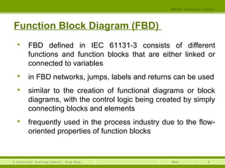
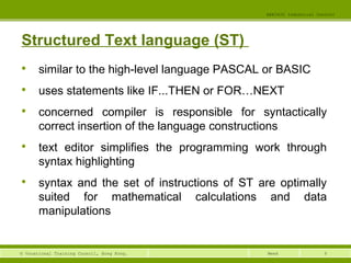
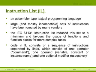
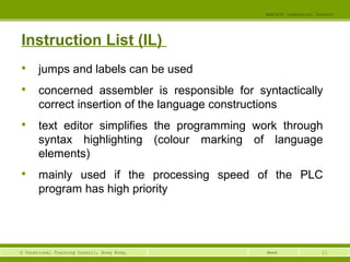
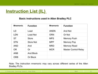
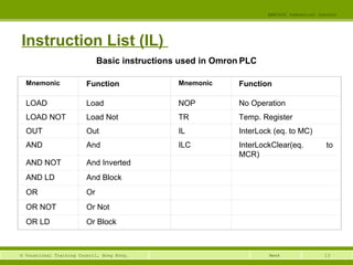
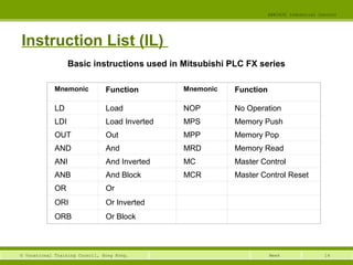
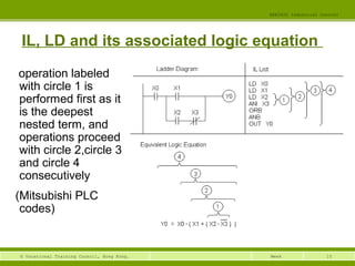
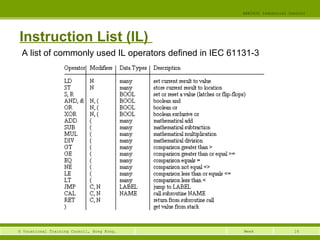
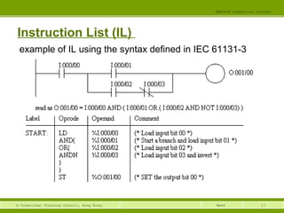
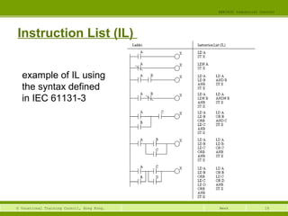
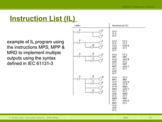
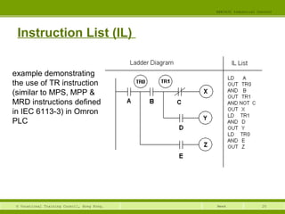
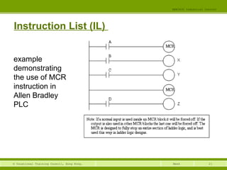
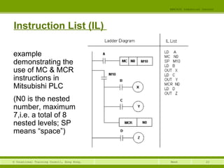
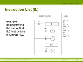
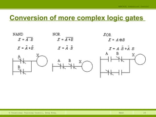
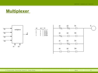
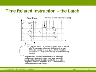
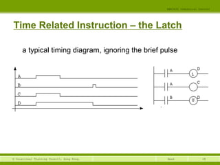
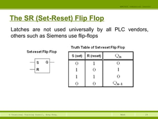
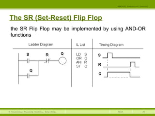
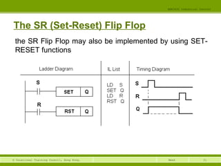
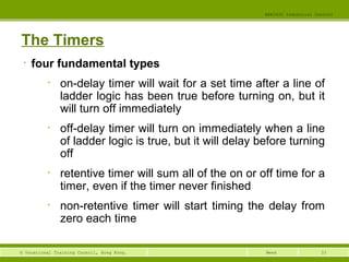
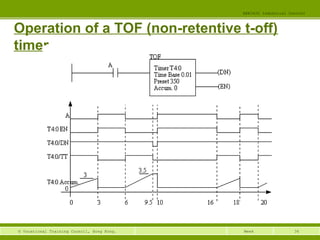
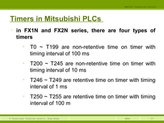
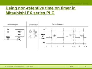
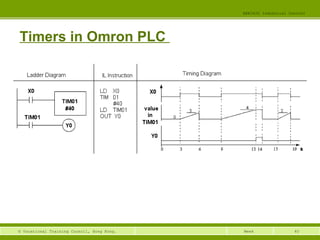
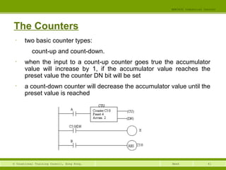
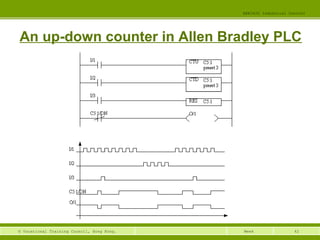
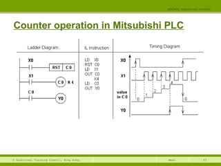
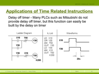
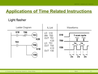
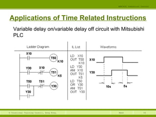
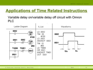
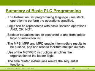
This document provides an overview of programmable logic controller (PLC) programming. It discusses the IEC 61131 standards for PLC programming languages including ladder logic, sequential function charts, function block diagrams, structured text, and instruction list. It also provides examples of programming basics like logic gates, latches, timers, and shift registers in ladder logic for different PLC brands like Allen-Bradley, Mitsubishi, and Omron.
This document provides an overview of basics control functions in PCS 7, including:
- An introduction to the Advanced Process Library (APL) blocks, which use structures to pass both process values and signal status through a single interconnection.
- Details on how signal status is implemented and displayed as symbols or hexadecimal values in the APL to indicate quality.
- A comparison of how standard and APL blocks handle passing signal status.
- Information on group status formation and priority in technological blocks.
The document discusses the basics of programmable logic controller (PLC) programming including PLC architecture, memory organization, programming languages, ladder logic instructions, addressing schemes, and programming techniques. Specifically, it covers the processor memory being divided into program and data memory, the ladder logic programming language using relay-type instructions like examine if closed and examine if open, addressing I/O locations by module and bit, and programming concepts such as parallel and nested rungs, internal control relays, and adjustments for different scan patterns.
This document provides an overview and summary of Siemens S7-300 PLC programming. It covers the STEP 7 programming software, comparing CPU models and modules, addressing modules, loading memory, data types, and instructions for statement list programming, logic, math, timers, and more. Programming examples are also included at the end.
This document provides an introduction to using STEP 7 software to program SIMATIC S7 programmable logic controllers. It outlines the basic procedure for creating a program using STEP 7, which involves combining hardware configuration with software programming. Practical exercises in subsequent chapters will demonstrate programming in Ladder Logic, Statement List, and Function Block Diagram to address inputs and outputs using basic binary logic operations.
SCADA systems collect data from remote locations and transmit it to a central control station. They use RTUs to collect and format data at remote sites, PLCs to monitor input devices and control output devices, HMIs for operators to interface with controllers, telemetry systems to wirelessly transmit data, and data acquisition to measure physical phenomena and convert it to digital values for analysis. Overall, SCADA systems allow centralized monitoring and control of equipment in various locations.
This document provides an overview of a basic PLC training course. It describes the major components of a PLC including the processor, memory, I/O modules, and programming device. It also outlines the course contents which will cover the history of PLCs, programming concepts, applications, and troubleshooting. The objectives are for participants to understand PLC components, programming, applications, and basic troubleshooting.
1. Fieldbus networks replace traditional 4-20 mA analog signals with digital communication over twisted-pair wiring.
2. The key changes are replacing the analog control system and field devices with digital ones that communicate over FOUNDATION fieldbus, and adding terminators to the wire pairs.
3. Devices can be connected in a bus, tree, daisy chain, or point-to-point topology with optional repeaters, bridges or gateways to extend the network or connect different segments.
Programmable logic controllers (PLCs) are digital electronic devices used to automate industrial processes. A PLC consists of a central processing unit, input/output modules, and a programming device. PLCs scan their program continuously and cyclically to monitor inputs and control outputs. They are programmed using ladder logic to perform functions like timing, counting, and controlling relays. PLCs are used widely in applications like process control, machinery control, and some CNC machine functions. Factors like the number of I/O points, memory, and scan time are considered when selecting a suitable PLC for an application.
This document provides an overview of distributed control systems (DCS) and programmable logic controllers (PLC). It defines DCS and PLCs, compares them, and describes their basic components and functions. The key aspects covered are:
1) DCS are integrated control systems used for complex, large-scale processes, while PLCs are used for discrete and small-scale control.
2) Both have centralized processing units and input/output modules to interface with field devices.
3) DCS are designed for continuous long-term use, while PLCs are more modular project-based systems.
PLC BASED AUTOMATED SYSTEM IN PROCESS INDUSTRY (Final Presentation)Shahid Faizee
This document describes a thesis project on implementing an automated PLC-based control system in a cement plant. The project involves developing motor block and group control block logic in Siemens Step 7 software to control crushers via a Siemens PLC and Expert Control System SCADA. Methodology includes defining inputs and outputs for motor and group blocks, designing submodules for start/stop, inputs, and outputs, and combining submodules into faceplates. The automated system is intended to reduce labor costs and improve performance by remotely monitoring and controlling plant operations.
PLC (Programmable Logic Controllers) are digital computers used to automate industrial processes. PLCs control machinery and processes through input and output modules connected to sensors and actuators. They are programmed using ladder logic and are widely used across industries like manufacturing. PLCs improve safety, increase productivity, and reduce costs by providing reliable control of automated industrial processes. DCS (Distributed Control Systems) are control systems used to automate large, complex industrial processes. DCS consists of multiple controllers connected to a central computer that work together to control a process. DCS offers flexibility, scalability, redundancy and integration with other systems, making it suitable for controlling complex industrial applications.
The document describes the timers/counters functionality of the 8051 microcontroller. It contains the following key details:
- The 8051 has two 16-bit timer/counters that can be independently programmed as timers or event counters.
- There are four special function registers (SFRs) associated with timer/counter operation: TMOD for timer mode control, TCON for timer control, and TH0/TL0 and TH1/TL1 for Timer 0 and Timer 1 values.
- The timers can be configured into four modes using the M1 and M0 bits in TMOD: 13-bit counter, 16-bit counter, 8-bit counter with auto-reload, and split operation
This document provides information about an embedded systems course offered at Maharajas Technological Institute. It includes details like the course code, credits, syllabus modules covering AVR microcontrollers and programming in assembly and C languages. It also discusses concepts like microcontrollers, AVR architecture, memory organization and instruction set of AVR microcontrollers. Examples are given of assembly language instructions like MOV, LDI, STS etc. and applications of embedded systems in various domains.
A comprehensive formal verification solution for ARM based SOC design chiportal
This document discusses Jasper's formal verification solutions for ARM processor-based system-on-chip (SoC) designs. It describes how Jasper can be used at the IP level to verify ARM Cortex processors and at the system level to verify aspects of full SoCs such as protocol verification, deadlock detection, and connectivity verification. Customers mentioned include Ericsson, Apple, Sony, and AMCC.
The document provides an overview of a Siemens S7-200 PLC training course. It discusses the history and advantages of PLCs over classical control systems. It then outlines the course contents which include introductions to PLC hardware configuration, programming languages, instructions like logic, timers, counters, and memory types. It also provides examples of programming concepts like inputs, outputs, timers, and counters.
This document provides an overview of programmable logic controllers (PLCs). It discusses the history of PLCs, how they were developed to replace relay-based control systems. The key components of a PLC including the processor, memory, and input/output modules are described. Examples of PLC programming languages and applications in industrial automation like machine control, food/beverage processing, and material handling are provided. Advantages of PLCs include fast operation, modularity, ease of maintenance, and improved productivity. Disadvantages include initial high costs and difficulty changing or replacing systems. PLCs have become widely used in industrial automation applications ranging from simple to complex control systems.
The document discusses improvements and new features in Yokogawa Electric Corporation's CENTUM CS 3000 process automation software. CENTUM CS 3000 R3.07 focuses on enhancing integration capabilities and the human-machine interface. New features include improved migration tools, expanded PROFIBUS DP support, enhanced integration with plant asset management systems, and an updated HMI with multi-monitor support. The updates aim to increase visibility of real-time plant data and diagnostic information across different systems.
This document describes the new compact CPUs that supplement the S7-300 small control system. It provides an overview of the different CPU models, their specifications and onboard I/O, counting, communication, and memory capabilities. The compact CPUs offer a low-cost control solution for automation applications with integral analog and digital I/O, counting, PWM, basic motion control, and MPI or PROFIBUS DP communications without additional hardware.
This document discusses CPLDs and the Altera MAX architecture. It describes how CPLDs integrate multiple PALs onto a single chip for more complex logic than a single PAL can provide. It then details the key components of the Altera MAX architecture, including Logic Array Blocks containing macrocells with programmable AND and OR arrays. Logic expanders allow implementing functions requiring more product terms. Programmable inversion can further reduce needed product terms. The MAX 7000 series uses this architecture with additional programmable interconnect and I/O control blocks.
Digital control systems provide more flexible and precise control over industrial processes compared to previous pneumatic and analog electronic implementations. A digital control system (DCS) collects data through local control units and uses a data highway and general purpose computer to implement advanced control algorithms across multiple control loops and processes in a programmable way.
This document provides an overview of PLC programming methods using common programming languages. It discusses ladder logic and mnemonic code programming. The objectives are to familiarize students with PLC programming systems, explain programming methods using ladder logic and mnemonic code, understand logic functions and instructions, and explain timer/counter functions and applications. Common programming languages like ladder logic, instruction list, structured text, sequential function charts and function block diagrams are also introduced.
- Kumar N VISION STATEMENT outlines the company's goal to be a leading provider of quality engineering solutions and support through continuous improvement.
- The company provides application engineering, panel engineering, product sales, and training services across various industries including defense, automation, and manufacturing.
- The document discusses concepts of industrial automation including how PLCs automate processes by replacing human functions like senses, movement, and decision making with electronic and mechanical controls.
Students will learn about embedded systems and ARM processors. The key aspects covered include:
- The RISC design philosophy adapted by ARM and typical embedded system hardware/software.
- The ARM instruction set and how it differs from pure RISC to suit embedded applications.
- The major hardware components of an embedded system including the ARM processor, controllers, peripherals, memory, and buses.
- Embedded system memory characteristics like hierarchy, width and common memory types.
- How peripherals connect and interface with the external world.
Practical Distributed Control Systems (DCS) for Engineers and TechniciansLiving Online
This workshop will cover the practical applications of the modern Distributed Control System (DCS). Whilst all control systems are distributed to a certain extent today and there is a definite merging of the concepts of a DCS, Programmable Logic Controller (PLC) and SCADA and despite the rapid growth in the use of PLC’s and SCADA systems, some of the advantages of a DCS can still be said to be Integrity and Engineering time.
Abnormal Situation Management and Intelligent Alarm Management is a very important DCS issue that provides significant advantages over PLC and SCADA systems.
Few DCSs do justice to the process in terms of controlling for superior performance – most of them merely do the basics and leave the rest to the operators. Operators tend to operate within their comfort zone; they don’t drive the process “like Vettel drives his Renault”. If more than one adverse condition developed at the same time and the system is too basic to act protectively, the operator would probably not be able to react adequately and risk a major deviation.
Not only is the process control functionality normally underdeveloped but on-line process and control system performance evaluation is rarely seen and alarm management is often badly done. Operators consequently have little feedback on their own performance and exceptional adverse conditions are often not handled as well as they should be. This workshop gives suggestions on dealing with these issues.
The losses in process performance due to the inadequately developed control functionality and the operator’s utilisation of the system are invisible in the conventional plant and process performance evaluation and reporting system; that is why it is so hard to make the case for eliminating these losses. Accounting for the invisible losses due to inferior control is not a simple matter, technically and managerially; so it is rarely attempted. A few suggestions are given in dealing with this.
Why are DCS generally so underutilised? Often because the vendor minimises the applications software development costs to be sure of winning the job, or because he does not know enough about the process or if it is a green-field situation, enough could not be known at commissioning time but no allowance was made to add the missing functionality during the ramp-up phase. Often the client does not have the technical skills in-house to realise the desired functionality is missing or to adequately specify the desired functionality.
This workshop examines all these issues and gives suggestions in dealing with them and whilst not being by any means exhaustive provides an excellent starting point for you in working with a DCS.
MORE INFORMATION: http://www.idc-online.com/content/practical-distributed-control-systems-dcs-engineers-technicians-2
This document discusses various constructs that can be used in Verilog testbenches, including loops, parallel blocks, named blocks, file I/O, and functions. It provides examples of while, repeat, forever loops as well as fork/join blocks for parallel execution. It also covers disabling blocks, opening and closing files, and reading and writing to files using commands like $fopen, $fdisplay, $fgets, and $fscanf. Functions are described as having inputs, a single output, and implementing combinational behavior using blocking assignments.
A microcontroller is a self-contained system with peripherals, memory and a processor that can be embedded in consumer products and machinery. Microcontrollers contain CPU, RAM, ROM, I/O ports, timers and counters to control input and output devices like sensors, displays and relays. They are used in applications where cost, power and space are critical constraints.
The document describes an 8085 microprocessor development system board containing an 8085 CPU, 8KB EPROM, 8KB RAM, 8255 PPI I/O device, and 8251 USART serial communication device. The memory map allocates addresses 0000H-1FFFH for EPROM and 2000H-3FFFH for RAM. The I/O map assigns addresses 40H-41H for the USART and 80H-83H for the 8255 PPI ports and control register. The 8255 PPI is described as having ports A, B, C that can be individually programmed for input or output. The USART handles serial communication to connect the board to a computer.
This document provides an overview of a course on basic programmable logic controller (PLC) programming. It covers various PLC programming languages and standards including ladder logic, function block diagram, structured text, and instruction list. Examples are provided for programming techniques using these languages for different PLC manufacturers. Timers and flip-flops are also discussed as common functions used in PLC programming.
This document provides an overview of programmable logic controllers (PLCs) and their hardware components. It discusses the basic components of a PLC including the power supply, central processing unit, input/output terminals, and indicator lights. It also describes common input and output devices used with PLCs such as sensors, actuators, and relays. The document discusses how inputs are connected to a PLC and converted to a format readable by its logic. It also describes how PLCs convert internal logic levels to external voltage levels on the outputs. Finally, it summarizes key aspects of PLC hardware and wiring.
This document provides an overview of an advanced PLC programming lecture for a course on industrial control. It discusses the structure and programming of Mitsubishi FX series PLCs, including details on hardware components like inputs, outputs, auxiliary relays and data registers. It also covers advanced programming techniques like special instructions, representation of operands, and data formats including bit devices, word devices, signed binary, hexadecimal, BCD, scientific notation and floating point values.
This document provides an overview of the EEC3420 Industrial Control course. It discusses Programmable Logic Controllers (PLCs), including their hardware components, operating principles, background and advantages over traditional relay logic systems. The document also describes typical PLC applications, inputs/outputs, programming languages according to international standards, and the internal working cycle of a PLC.
This document outlines the content of a lecture series on advanced PLC programming using Mitsubishi FX series PLCs. It covers the structure of Mitsubishi PLCs, advanced programming techniques, hardware details like inputs, outputs, auxiliary relays and data registers. It also describes representation of operands, instructions for program flow, move/compare, arithmetic/logical operations, rotation/shift, data operations and high-speed processing.
This document discusses the basics of programmable logic controller (PLC) programming and architecture. It covers topics like PLC memory organization, input/output table files, ladder logic programming, and scan processes. The key points are that PLCs use ladder logic programming which resembles relay-based logic, their memory is divided between program and data areas, and they operate by continuously scanning inputs, running the user program, and updating outputs.
This document discusses the basics of programmable logic controller (PLC) programming and architecture. It covers PLC memory organization, including the separation of program and data memory. The processor continually performs an input/output scan and program scan in a repeating cycle. Ladder logic is introduced as the most common PLC programming language, using basic instructions like examine if closed and output energize analogous to relay contacts and coils. The document explains how the PLC scans the ladder logic program sequentially to determine the state of outputs.
The document provides an overview of programmable logic controllers (PLCs). It discusses the origins and development of PLCs, moving from complex relay-based control systems to more flexible PLCs. The key applications of PLCs are in industrial automation, where they can flexibly control processes. PLCs now support many functions beyond basic logic, such as timers, counters, memory functions, and mathematical operations. The document also introduces the IEC 61131 standard for PLC programming.
This document summarizes a seminar on programmable logic controllers (PLCs) given by electrical engineering students at a university. It provides an introduction to PLCs, covering their history, major components, operational sequence, programming languages including ladder logic, types of PLCs according to inputs/outputs and construction, and examples of using PLCs to start and stop a motor. Applications of PLCs are discussed along with advantages like reliability and flexibility and disadvantages like limited design options. The future scope of PLCs is also covered, with references provided.
This presentation provides an overview of programmable logic controllers (PLCs). It discusses what a PLC is, the history and major components of PLCs. The operational sequence and common programming languages like ladder logic are described. An example is given of using ladder logic to start and stop a motor. PLCs provide benefits like reliability, flexibility, cost-effectiveness and ease of maintenance. They are widely used in industrial automation applications such as robotics, materials handling, and process control. The presentation concludes by thanking the audience.
Difference between micro controller and PLC, Introduction to PLC.,
PLC structure at glance,
PLC structure,
I/O processing,
Ladder Diagram Fundamentals,
PLC for industrial Prose cc control,
Selection criteria for PLC
The document provides an overview of programmable logic controllers (PLCs):
1. PLCs were developed in the 1960s as an alternative to complex relay control systems and offered advantages like simple programming, program changes without system intervention, smaller size, lower cost, and higher reliability.
2. PLCs are now used in a wide range of industrial automation applications. In addition to basic input/output control, modern PLCs can perform tasks like timing, counting, arithmetic, communication, visualization, and process control.
3. A basic PLC system consists of an input module, central processing unit, output module, and power supply. The central processing unit runs the user-created control program
The document provides an overview of programmable logic controllers (PLCs):
1. PLCs were developed in the 1960s as an alternative to complex relay control systems and offered benefits like simple programming, program changes without system intervention, smaller size, lower cost, and improved reliability compared to relay systems.
2. PLCs are now used in a wide range of industrial automation applications. In addition to basic input/output control, modern PLCs can perform tasks like timing, counting, arithmetic, communication, visualization, and process control.
3. A basic PLC system consists of an input module, central processing unit, output module, and power supply. The central processing unit runs the user
This document introduces programmable logic controllers (PLCs) and their configuration procedure. It begins with a brief history of PLCs and their advantages over traditional hardwired control systems. The key components of a PLC including the power supply, central processing unit, input/output modules, and programming devices are described. The five most common PLC programming languages - ladder logic, sequential function charts, function block diagram, structured text, and instruction list - are also outlined. The document concludes with step-by-step instructions for creating a project in IndraWorks engineering software to configure a PLC.
This document discusses flowchart-based process control design using programmable logic controllers (PLCs). It covers creating flowcharts to represent sequential processes, and implementing those flowcharts in PLC programs using block logic or sequence bits. High-level flowchart representations of processes can be realized using high-level instructions from PLCs like the Mitsubishi FX. An example cart control system flowchart is implemented using MOV, CMP and other FX instructions to move the cart between positions based on limit switch and call button inputs.
PLC: Principios básicos del controlador lógico programable mediante el softwa...SANTIAGO PABLO ALBERTO
This document provides an introduction and overview of:
1) The Lab-Volt PLC Trainer hardware, including its inputs, outputs, indicators, and connections.
2) The RSLogix 500 software used to program the PLC, including how to create and organize projects, programs, and files.
3) The basics of ladder logic programming, including logical continuity, input/output devices, AND and OR logic, and documenting programs.
This document discusses designing control processes using flowchart techniques. It begins by defining the basic components of a flowchart like blocks, arrows, and decision points. It then provides examples of implementing simple sequential processes as flowcharts, including a water tank filling process. The document explains two methods for representing flowcharts in ladder logic programs using block logic or sequence bits. Finally, it presents a example of using flowcharts and high-level instructions to control the movement of a cart system.
The document provides an overview of programmable logic controllers (PLCs). It discusses that PLCs were introduced in the late 1960s as replacements for relay-based controls. The major components of a PLC are the processor, power supply, input/output modules, and a programming device. PLCs operate by performing a self-test, scanning inputs, solving ladder logic to update outputs in memory, and then scanning outputs to devices. Common PLC programming languages include ladder logic, functional block diagrams, sequential function charts, and Boolean mnemonics.
This document discusses Programmable Logic Controllers (PLCs). It provides a brief history of PLCs, describing how they were introduced in the 1960s as replacements for relay logic and have since evolved with the integration of microprocessors. The key components of a PLC like the power supply, processor, I/O modules, and programming device are defined. Common PLC programming languages including ladder logic are explained and examples are provided. Advantages like reliability and flexibility and disadvantages such as proprietary aspects are reviewed. Finally, common industrial applications and leading PLC brands are listed.
This document discusses DC to AC conversion using inverters. It describes various inverter topologies including single phase half bridge and full bridge inverters as well as three phase full bridge inverters. It discusses modulation techniques such as sinusoidal pulse width modulation to generate sinusoidal AC outputs. Examples of applications like motor drives and solar power generation are provided.
This document introduces an advanced power electronics course. It discusses the lecturer's background and qualifications. It outlines some ground rules for students, including submitting assignments on time, maintaining academic integrity, and being respectful. It then provides a general overview of the course, defining power electronics and discussing some key applications like power supplies, inverters, and motor drives. It also introduces some important power electronic components like capacitors, inductors, diodes, and active switching devices.
This document provides an overview of pulse-width modulated (PWM) DC/DC converters. It discusses typical applications, topologies including non-isolated converters like buck, boost and buck-boost converters. The principles of DC/DC converters like conversion ratio and voltage/current waveforms are introduced. Modes of operation for buck converters in continuous and discontinuous mode are examined. Component ratings for voltage and current are also covered.
This document summarizes different types of isolated DC/DC converters. It discusses flyback converters, which are derived from buck-boost converters by adding a coupled inductor. Flyback converters can operate in continuous or discontinuous mode. Phase-shift full-bridge converters are suitable for high power applications. They consist of a full-bridge inverter and rectifier, with legs switched alternately at different phases to regulate output voltage. The document also reviews transformer fundamentals and voltage conversion ratios for different isolated converter types.
This chapter discusses resonant DC/DC converters. Hard-switching converters experience high switching losses which reduce efficiency. Resonant converters reduce switching losses by forcing zero-current or zero-voltage switching through resonant circuits. This is accomplished by adding inductors and capacitors to shape current and voltage waveforms. While more efficient, resonant converters have more complex circuitry than hard-switching converters.
Chapter 6 - Modelling and Control of Converters.pdfbenson215
This document discusses modeling and control of power converters. It begins by explaining that converters are typically controlled with closed-loop control to maintain regulated output levels despite variations, rather than open-loop control. It then covers obtaining small-signal dynamic models of converters using state-space averaging techniques to design closed-loop controllers. As an example, it derives the small-signal model of a buck converter in continuous mode through state-space equations, averaging, linearization, and Laplace transformation to obtain a transfer function. The document provides procedures for modeling other converters and analyzing converter characteristics from the frequency-domain models.
This document summarizes Chapter 4 of a textbook on AC/DC and DC/AC conversion. It discusses uncontrollable and controllable AC-DC converters, including rectifiers, power factor, and harmonics. It then covers full-wave and controlled rectifiers, thyristor triggering, and integrated power modules. The document also discusses power factor correction, harmonic distortion, and total harmonic distortion. Finally, it summarizes various power quality issues faced by utilities.
This document discusses electromagnetic interference (EMI) in power electronics. It defines EMI and describes how it is generated internally in power electronic circuits and transmitted through electrical conduction, electromagnetic induction, and radiation. The document outlines international standards for EMI, sources of EMI, and methods for suppressing EMI, including EMI filters, active harmonic compensation, and proper design of circuit components.
(1) The document discusses AC drive systems including AC voltage controllers, cycloconverters, and PWM control.
(2) AC voltage controllers are used to control the speed of AC induction motors by varying the firing angle. Cycloconverters can generate variable frequency output from a fixed frequency input using a dual converter configuration.
(3) PWM control improves performance over simple voltage control by reducing harmonic content in the output waveform. Advanced PWM techniques like sinusoidal, trapezoidal, and stepped modulation further optimize the output waveform.
1. revision on 3 phase conventional inverterbenson215
This document discusses revisions made to a 3-phase conventional inverter. The inverter is used to convert DC power from sources like solar panels into 3-phase AC power that can be fed into the electric grid or used by electric motors. Some changes were made to the control system and components to improve the inverter's performance and efficiency.
1. revision on 3 phase controlled rectifierbenson215
This document discusses a 3-phase controlled rectifier circuit that uses thyristors to control the rectification of a 3-phase AC input. The circuit allows controlling the DC output voltage by adjusting the firing angle of the thyristors. When the thyristors are fired earlier in their half-cycles, more voltage will be rectified and added to the DC output.
This document discusses dimensioning a drive system, including:
1. The general steps of dimensioning including selecting the motor and frequency converter.
2. Common load types like constant torque, quadratic torque, and constant power loads.
3. How a motor's thermal loadability decreases at lower speeds for self-ventilated motors, but separate cooling allows overloading at low speeds.
A 2-phase servo motor is described with 17 numbered points providing details about its construction and operation. Key details include that it uses 2 energized coils to rotate the motor shaft in either direction and has a feedback potentiometer to sense shaft position and complete a control loop.
1. A linear induction motor is essentially a rotating squirrel cage induction motor that has been opened out flat, producing linear force instead of rotary torque.
2. Linear motors have advantages like no moving parts, silent operation, and ease of control and installation. Applications include sliding doors, conveyors, and vehicle propulsion.
3. Linear motors require an AC power supply and speed can be controlled through phase control or feedback systems. Different linear motor designs exist including ironcore, aircore, and slotless types.
This document provides an overview of brushless DC motors. It discusses their structure, drive circuits, equivalent circuit model, and performance characteristics. Brushless DC motors have a rotor with permanent magnets and stator windings similar to AC motors. They use electronic commutation instead of brushes and commutators, making them maintenance-free. The document covers various drive circuit topologies including unipolar and bipolar drives. It also presents the dynamic and steady-state equivalent circuits and performance equations of brushless DC motors.
This document provides an introduction to servo systems, including:
1. It defines a servo system as one that controls mechanical devices in compliance with varying position or speed target values from a command.
2. It describes three major types of control systems - open loop, semi-closed loop, and full-closed loop - and compares their features such as precision, ability to handle load fluctuations, and complexity.
3. It outlines the typical components of a servo system, including the servo motor, detector, driver, and position controller, and describes how they work together to provide position and speed feedback control of the motor.
The document discusses reluctance and hysteresis motors. Reluctance motors work by using magnetic poles that attract and repel to rotate a shaft, while hysteresis motors use materials that retain magnetic fields to convert electrical current into mechanical motion. Both motor types provide alternative options to traditional induction motors.
This document provides an overview of sensors, actuators, and programmable logic controller (PLC) applications in industrial control. It discusses various types of common sensors such as inductive proximity, capacitive, optical, and mechanical contact sensors. It also describes actuator types including solenoids, valves, cylinders, and motors. Finally, it provides examples of how PLCs can be used with these sensors and actuators for industrial automation and control applications.
Tools & Techniques for Commissioning and Maintaining PV Systems W-Animations ...Transcat
Join us for this solutions-based webinar on the tools and techniques for commissioning and maintaining PV Systems. In this session, we'll review the process of building and maintaining a solar array, starting with installation and commissioning, then reviewing operations and maintenance of the system. This course will review insulation resistance testing, I-V curve testing, earth-bond continuity, ground resistance testing, performance tests, visual inspections, ground and arc fault testing procedures, and power quality analysis.
Fluke Solar Application Specialist Will White is presenting on this engaging topic:
Will has worked in the renewable energy industry since 2005, first as an installer for a small east coast solar integrator before adding sales, design, and project management to his skillset. In 2022, Will joined Fluke as a solar application specialist, where he supports their renewable energy testing equipment like IV-curve tracers, electrical meters, and thermal imaging cameras. Experienced in wind power, solar thermal, energy storage, and all scales of PV, Will has primarily focused on residential and small commercial systems. He is passionate about implementing high-quality, code-compliant installation techniques.
Accident detection system project report.pdfKamal Acharya
The Rapid growth of technology and infrastructure has made our lives easier. The
advent of technology has also increased the traffic hazards and the road accidents take place
frequently which causes huge loss of life and property because of the poor emergency facilities.
Many lives could have been saved if emergency service could get accident information and
reach in time. Our project will provide an optimum solution to this draw back. A piezo electric
sensor can be used as a crash or rollover detector of the vehicle during and after a crash. With
signals from a piezo electric sensor, a severe accident can be recognized. According to this
project when a vehicle meets with an accident immediately piezo electric sensor will detect the
signal or if a car rolls over. Then with the help of GSM module and GPS module, the location
will be sent to the emergency contact. Then after conforming the location necessary action will
be taken. If the person meets with a small accident or if there is no serious threat to anyone’s
life, then the alert message can be terminated by the driver by a switch provided in order to
avoid wasting the valuable time of the medical rescue team.
Blood finder application project report (1).pdfKamal Acharya
Blood Finder is an emergency time app where a user can search for the blood banks as
well as the registered blood donors around Mumbai. This application also provide an
opportunity for the user of this application to become a registered donor for this user have
to enroll for the donor request from the application itself. If the admin wish to make user
a registered donor, with some of the formalities with the organization it can be done.
Specialization of this application is that the user will not have to register on sign-in for
searching the blood banks and blood donors it can be just done by installing the
application to the mobile.
The purpose of making this application is to save the user’s time for searching blood of
needed blood group during the time of the emergency.
This is an android application developed in Java and XML with the connectivity of
SQLite database. This application will provide most of basic functionality required for an
emergency time application. All the details of Blood banks and Blood donors are stored
in the database i.e. SQLite.
This application allowed the user to get all the information regarding blood banks and
blood donors such as Name, Number, Address, Blood Group, rather than searching it on
the different websites and wasting the precious time. This application is effective and
user friendly.
Mechatronics is a multidisciplinary field that refers to the skill sets needed in the contemporary, advanced automated manufacturing industry. At the intersection of mechanics, electronics, and computing, mechatronics specialists create simpler, smarter systems. Mechatronics is an essential foundation for the expected growth in automation and manufacturing.
Mechatronics deals with robotics, control systems, and electro-mechanical systems.
Digital Twins Computer Networking Paper Presentation.pptxaryanpankaj78
A Digital Twin in computer networking is a virtual representation of a physical network, used to simulate, analyze, and optimize network performance and reliability. It leverages real-time data to enhance network management, predict issues, and improve decision-making processes.
Height and depth gauge linear metrology.pdfq30122000
Height gauges may also be used to measure the height of an object by using the underside of the scriber as the datum. The datum may be permanently fixed or the height gauge may have provision to adjust the scale, this is done by sliding the scale vertically along the body of the height gauge by turning a fine feed screw at the top of the gauge; then with the scriber set to the same level as the base, the scale can be matched to it. This adjustment allows different scribers or probes to be used, as well as adjusting for any errors in a damaged or resharpened probe.
Build the Next Generation of Apps with the Einstein 1 Platform.
Rejoignez Philippe Ozil pour une session de workshops qui vous guidera à travers les détails de la plateforme Einstein 1, l'importance des données pour la création d'applications d'intelligence artificielle et les différents outils et technologies que Salesforce propose pour vous apporter tous les bénéfices de l'IA.
DEEP LEARNING FOR SMART GRID INTRUSION DETECTION: A HYBRID CNN-LSTM-BASED MODELijaia
As digital technology becomes more deeply embedded in power systems, protecting the communication
networks of Smart Grids (SG) has emerged as a critical concern. Distributed Network Protocol 3 (DNP3)
represents a multi-tiered application layer protocol extensively utilized in Supervisory Control and Data
Acquisition (SCADA)-based smart grids to facilitate real-time data gathering and control functionalities.
Robust Intrusion Detection Systems (IDS) are necessary for early threat detection and mitigation because
of the interconnection of these networks, which makes them vulnerable to a variety of cyberattacks. To
solve this issue, this paper develops a hybrid Deep Learning (DL) model specifically designed for intrusion
detection in smart grids. The proposed approach is a combination of the Convolutional Neural Network
(CNN) and the Long-Short-Term Memory algorithms (LSTM). We employed a recent intrusion detection
dataset (DNP3), which focuses on unauthorized commands and Denial of Service (DoS) cyberattacks, to
train and test our model. The results of our experiments show that our CNN-LSTM method is much better
at finding smart grid intrusions than other deep learning algorithms used for classification. In addition,
our proposed approach improves accuracy, precision, recall, and F1 score, achieving a high detection
accuracy rate of 99.50%.
Prediction of Electrical Energy Efficiency Using Information on Consumer's Ac...PriyankaKilaniya
Energy efficiency has been important since the latter part of the last century. The main object of this survey is to determine the energy efficiency knowledge among consumers. Two separate districts in Bangladesh are selected to conduct the survey on households and showrooms about the energy and seller also. The survey uses the data to find some regression equations from which it is easy to predict energy efficiency knowledge. The data is analyzed and calculated based on five important criteria. The initial target was to find some factors that help predict a person's energy efficiency knowledge. From the survey, it is found that the energy efficiency awareness among the people of our country is very low. Relationships between household energy use behaviors are estimated using a unique dataset of about 40 households and 20 showrooms in Bangladesh's Chapainawabganj and Bagerhat districts. Knowledge of energy consumption and energy efficiency technology options is found to be associated with household use of energy conservation practices. Household characteristics also influence household energy use behavior. Younger household cohorts are more likely to adopt energy-efficient technologies and energy conservation practices and place primary importance on energy saving for environmental reasons. Education also influences attitudes toward energy conservation in Bangladesh. Low-education households indicate they primarily save electricity for the environment while high-education households indicate they are motivated by environmental concerns.
Software Engineering and Project Management - Software Testing + Agile Method...Prakhyath Rai
Software Testing: A Strategic Approach to Software Testing, Strategic Issues, Test Strategies for Conventional Software, Test Strategies for Object -Oriented Software, Validation Testing, System Testing, The Art of Debugging.
Agile Methodology: Before Agile – Waterfall, Agile Development.